Lincoln Nautilus: Roof Opening Panel / Roof Opening Panel - System Operation and Component Description. Description and Operation
System Operation
Roof Opening Panel Operating System
The accessory delay relay in the BCM supplies voltage through fuse F31 (10A) to the roof opening panel sliding glass motor and roof opening panel shield motor allowing the motors to respond to roof opening panel control switch commands. The BCM activates the accessory delay relay whenever the ignition is in the RUN or ACC positions, or for a specific time when the ignition is changed from RUN or ACC to the OFF position. The roof opening panel sliding glass motor and roof opening panel shield motor receive voltage from BCM fuse F27 (30A), and ground from G303 for motor movement. The roof opening panel switch is combined with the overhead console and is serviced with the overhead console. The switches apply a ground signal to the motors depending on the switch position and the motors respond accordingly. The roof opening panel switch receives ground from G403.
When the vehicle is in motion the BCM sends a PWM signal to the roof opening panel sliding glass motor which then will apply increased force while closing the roof opening panel sliding glass to reduce the possibility of bounce back.
Switch Operation
The roof opening panel is an electronically operated glass panel that can be opened, closed or tilted (vent position) by the roof opening panel control switch, the shield switch, and the vent switch. Actuating the switches supplies a signal to the roof opening panel glass and shield motor/module. The front sliding glass panel and the shield use two integrated motors/modules that are serviced as assemblies. The roof opening panel and shield has one-touch open and one-touch close features that are activated when the switch is pressed and immediately released (less than 0.5 seconds) on the open or close side of the switch. For manual control holding the switch depressed for more than 0.5 seconds will cancel one-touch operation and the sliding glass panel or shield will stop when the switch is released.
Shield Operation
When the shield OPEN switch is pressed and released the shield will automatically open and stop at the front of the roof opening panel fixed glass (comfort stop), leaving only the sliding glass panel exposed. Pressing and releasing the shield OPEN switch a second time (after the initial stop) will open the shield to the full open position. When the sliding glass panel is closed, the shield is open to any position beyond comfort stop and the shield CLOSE switch is pressed and released, the shield moves forward to the comfort stop position and stops. After stopping at the comfort stop position, pressing and releasing the shield Close switch again will fully close the shield. If the shield is in the closed position and the front sliding glass panel OPEN switch is pressed, the shield will perform a one-touch open operation automatically which will then be followed by the front sliding glass panel operation that was requested. To partially open or close the shield while it is moving, press shield OPEN or CLOSE switch again to stop the shield in the desired position.
Sliding Glass Panel Operation
When the front sliding glass panel OPEN switch is pressed and released the front sliding glass panel will automatically open and stop at a predetermined position before the fully open position (comfort position). Pressing and releasing the front sliding glass panel OPEN switch a second time (after the initial stop) will open the front sliding glass panel to the full open position. To fully close the front sliding glass panel, press and release the front sliding glass panel CLOSE switch. The front sliding glass panel will fully close. The front sliding glass panel movement can be stopped at any time in either direction by pressing the front sliding glass panel switch in either direction. The vent position can only be requested when the front sliding glass panel is in the fully closed position. To open to the vent position, press and release the vent switch. The front sliding glass panel will move to the vent position automatically. The front sliding glass panel can be fully closed from the vent position by pressing the front sliding glass panel CLOSE switch. If the shield is in the closed position and the front sliding glass panel OPEN switch is pressed, the shield will perform a one-touch open operation automatically which will then be followed by the front sliding glass panel operation that was requested. To partially open or close the front sliding glass panel from any position, press and hold the front sliding glass panel OPEN or CLOSE switch and release at the desired position.
Bounce Back - Front Sliding Glass Panel And Shield
The sliding glass panel and shield has a bounce back feature. If an obstacle has been detected as the front sliding glass panel or shield is closing, operation will automatically reverse and stop at a predetermined position.
Security Override
To override a bounce back condition (to overcome the resistance of ice on the front sliding glass panel seal for example), within 2 seconds of a bounce back event, press and hold the front sliding glass panel CLOSE switch. The front sliding glass panel will operate in manual mode with bounce back detection disabled until the switch is released.
Roof Opening Panel Fixed Glass
The
roof opening panel system on this vehicle includes a fixed roof panel
glass behind the front sliding glass panel. Any time this panel is
removed or adjusted the front sliding glass panel will need to be
initialized.
Refer to: Power Roof Opening Panel Initialization (501-17 Roof Opening Panel, General Procedures).
Comfort Stop
The roof opening panel will automatically close to approximately 8 in (20 cm) when driving above 35 mph (56 km/h) with the sliding glass panel open to reduce excessive wind noise. To override this feature to open the sliding glass panel to the desired position, press the OPEN or CLOSE switch. This feature only functions one time per key cycle.
Roof Opening Panel Motors - Glass and Shield
The roof opening panel motors contain integral electronics that control and monitor the glass or shield movement (for obstacle detection and one-touch operating features). The sliding glass panel motor and shield motor communicate to each other through a dedicated circuit within the roof opening panel jumper harness. The sliding glass panel motor and shield motor do not communicate to the vehicle network. The sliding glass panel and shield motors are the same but the shield motor connector pin 14 is connected to ground though the jumper harness to identify it as the shield motor within the configuration.
Jumper Harness and Communication
There is a jumper harness between roof opening panel C921 and both roof opening panel assembly motors (shield and front sliding glass panel motors) which includes a communication circuit that is used only for communication between the motors. If the communication circuit between the front sliding glass panel motor and shield motor is open or shorted the front sliding glass panel motor will only fully close the front sliding glass panel one time, then not operate. Also, if the communication circuit is open or shorted the shield motor will open fully, then only operate between fully open and the front of the fixed glass panel.
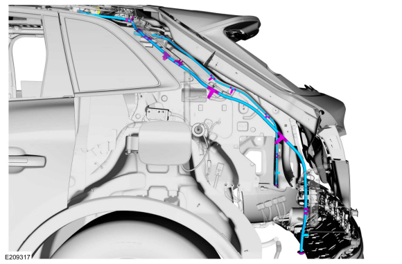
Roof Opening Panel Front Drain Hose Routing
.jpg)
Roof Opening Panel Rear Drain Hose Routing

 Roof Opening Panel. Diagnosis and Testing
DTC Chart: Roof Opening Panel
Diagnostics in this manual assume a certain skill level and knowledge of Ford-specific diagnostic practices. REFER to: Diagnostic Methods (100-00 General Information, Description and Operation)...
Other information:
Lincoln Nautilus 2018-2026 Service Manual: Module Controlled Functions - Component Location. Description and Operation
Item Description 1 RTM 2 DDM 3 RDM 4 BCM 5 PDM ..
Lincoln Nautilus 2018-2026 Service Manual: Specifications
Material Item Specification Fill Capacity Motorcraft® High Temperature Nickel Anti-Seize Lubricant XL-2 - Motorcraft® Wheel and Tire Cleaner ZC-37-A - General Specifications Item Specification Tire Inflation Tires See Safety Certi..
Categories
- Manuals Home
- 1st Generation Nautilus Owners Manual
- 1st Generation Nautilus Service Manual
- Folding the Exterior Mirrors - Vehicles With: Manual Folding Mirrors. Folding the Exterior Mirrors - Vehicles With: Power Folding Mirrors
- Drive Mode Control
- Replacing the Rear Wiper Blades
- New on site
- Most important about car
Locating the Pre-Collision Assist Sensors

If a message regarding a blocked sensor or camera appears in the information display, something is obstructing the radar signals or camera images. The radar sensor is behind the fascia cover in the center of the lower grille. With a blocked sensor or camera, the system may not function, or performance may reduce. See Pre-Collision Assist – Information Messages.