Lincoln Nautilus: Interior Lighting / Interior Lighting - Overview. Description and Operation
Overview
The interior lighting system consists of:
- Courtesy lamps
- Demand lamps
- Ambient lighting
The courtesy lamps subsystem consists of:
- Interior overhead lamps
- Luggage compartment lamp
- Liftgate cargo lamp
- Puddle lamps
- Front door illuminated scuff plates
- Exterior door handle lamps
- Door ajar switches (integrated into the door latches)
- Courtesy lamp switch (integrated into the front interior lamp)
- DDM
- PDM
- BCM
The courtesy lamps provide illumination to the vehicle interior and below the exterior mirrors when entering or exiting the vehicle or when requested using the courtesy lamp switch located on the front interior lamp assembly.
The demand lamps subsystem consists of:
- Interior lamps (map lamps)
- Vanity mirror lamps
- Glove box lamp
- BCM
The demand lamps provide illumination to specific areas within the vehicle when needed.
The BCM energizes the demand lamp relay to supply voltage to the demand lamps when the battery saver feature is not active.
The ambient lighting subsystem consists of:
- Ambient lighting Light Emitting Diodes (LEDs)
- FDIM (touchscreen)
- BCM
The ambient lighting is controlled using the FDIM (touchscreen) controls. The ambient lighting provides aesthetically colored illumination to the following locations for illuminated entry or when the ignition is in RUN with the parking lamps on:
- Floor console cup holders
- Floor console media bin (white only)
- Floor console storage bin (white only)
- Floor console pass through
- Instrument panel
- Interior door release handles
- Interior door trim
- Interior front door map pockets
- Front footwells
- Rear footwells (rear of floor console)

 Interior Lighting - System Operation and Component Description. Description and Operation
System Operation
System Diagram
Item
Description
1
BCM
2
DDM
3
PDM
4
APIM
5
FDIM
6
GWM
7
RGTM
8
Door Ajar Switches
9
Headlamp Switch
10
Overhead Console
11
Overhead Console
12
Rear Courtesy Lamp
13
LH Rear Courtesy Lamp
14
RH Rear Courtesy Lamp
15
..
Other information:
Lincoln Nautilus 2018-2026 Service Manual: Plastic Repairs. General Procedures
Special Tool(s) / General Equipment ALCV-200 Materials Name Specification Plastic Bonding AdhesiveTA-9 - Inspection NOTE: Plastics Identification WARNING: Before beginning any service procedure in this section, REFER to Safety Warnings in section 100-00 General Information. Failure to follow this instruction may result in serious personal ..
Lincoln Nautilus 2018-2026 Service Manual: Media Hub. Removal and Installation
Removal NOTE: Removal steps in this procedure may contain installation details. Open the media bin cover. Using a non-marring tool, release the clips and position the media hub out. Disconnect the connectors and remove the media hub. Installation To install, reverse the removal procedure...
Categories
- Manuals Home
- 1st Generation Nautilus Owners Manual
- 1st Generation Nautilus Service Manual
- Drive Mode Control
- Locating the Pre-Collision Assist Sensors
- Switching the Lane Keeping System On and Off. Switching the Lane Keeping System Mode
- New on site
- Most important about car
Parking Aid Indicators. Parking Aids – Troubleshooting
Parking Aid Indicators
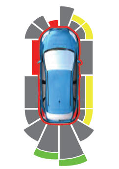
The system provides object distance indication through the information and entertainment display.
As the distance to the object decreases, the indicator waves and the lines move toward the vehicle icon. If there is no object detected, the distance indicator lines are grey.