Lincoln Nautilus: Rear Suspension / Lower Arm. Removal and Installation
Special Tool(s) / General Equipment
| Vehicle/Axle Stands |
Removal
NOTICE: Suspension fasteners are critical parts that affect the performance of vital components and systems. Failure of these fasteners may result in major service expense. Use the same or equivalent parts if replacement is necessary. Do not use a replacement part of lesser quality or substitute design. Tighten fasteners as specified.
-
Remove the wheel and tire.
Refer to: Wheel and Tire (204-04A Wheels and Tires, Removal and Installation).
-
NOTICE: The rear suspension height sensor must be disconnected from the lower control arm prior to servicing suspension components or damage to the suspension height sensor and/or the vehicle dynamic suspension system may occur. The sensor will need to be recalibrated after reassembly.
If equipped.
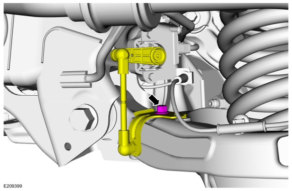
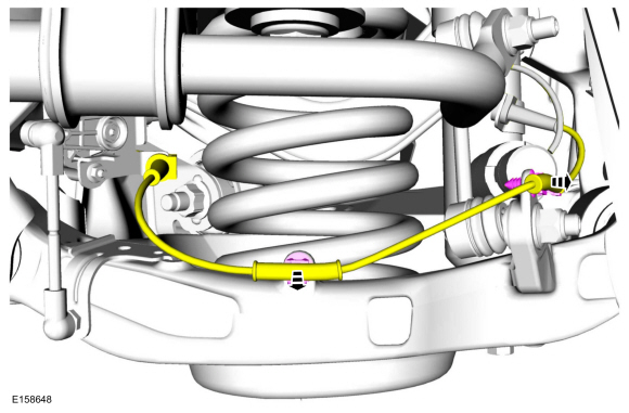
Remove the rear height sensor arm bracket bolt and position the rear height sensor arm bracket aside.
 |
-
If equipped.
Unclip the rear shock absorber wire harness retaining clips and position the harness aside.
 |
-
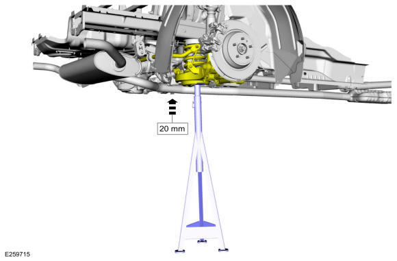
NOTICE: Suspension fasteners are critical parts that affect the performance of vital components and systems. Failure of these fasteners may result in major service expense. Use the same or equivalent parts if replacement is necessary. Do not use a replacement part of lesser quality or substitute design. Tighten fasteners as specified.
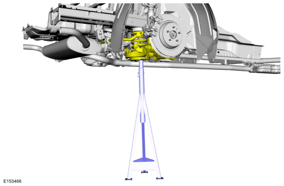
Raise the suspension approximately 20mm from rebound condition.
Use the General Equipment: Vehicle/Axle Stands
 |
-
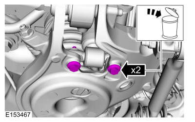
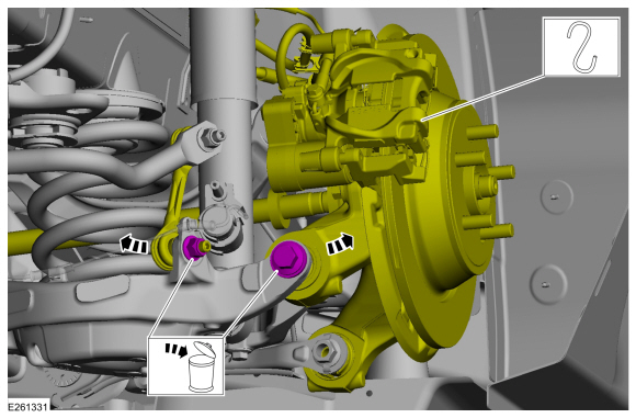
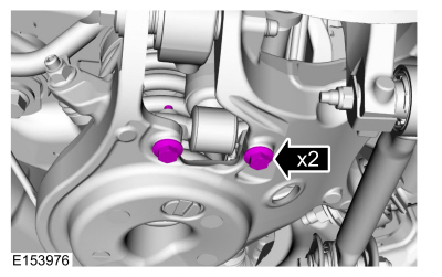
Remove and discard the rear shock absorber lower bolts.
 |
-
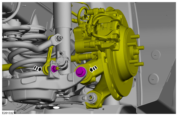
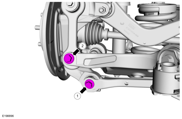
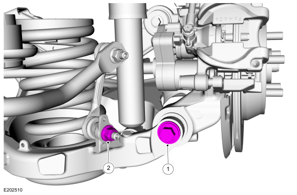
Remove and discard the toe link-to-wheel knuckle bolt and the lower arm vertical link lower bolt.
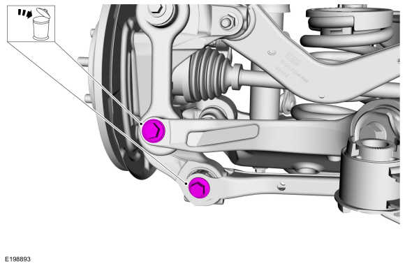 |
-
NOTE: Make sure that the knuckle is supported with suitable retainingstraps.
-
Remove and discard the rear stabilizer bar link lower nut and position the rear stabilizer bar link aside.
-
Remove and discard lower arm-to-wheel knuckle bolt and separate the wheel knuckle from the lower arm.
-
Remove and discard the rear stabilizer bar link lower nut and position the rear stabilizer bar link aside.
 |
-
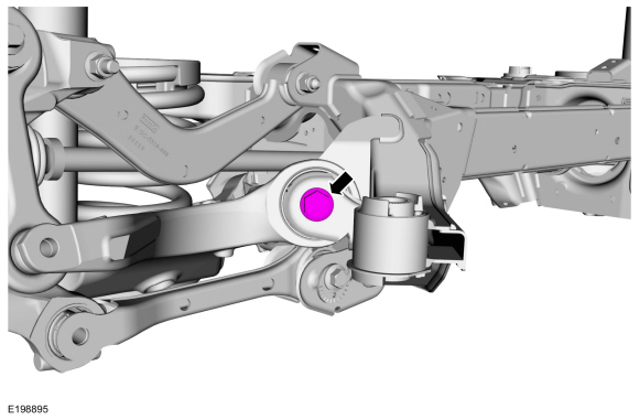
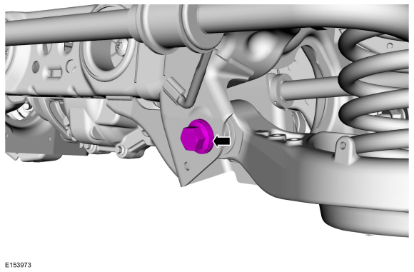
Remove and discard the lower arm-to-frame forward bolt.
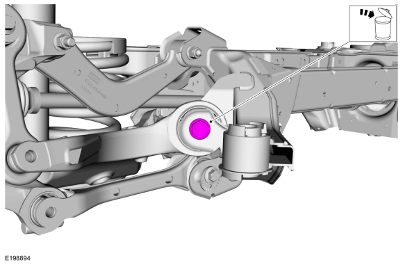 |
-
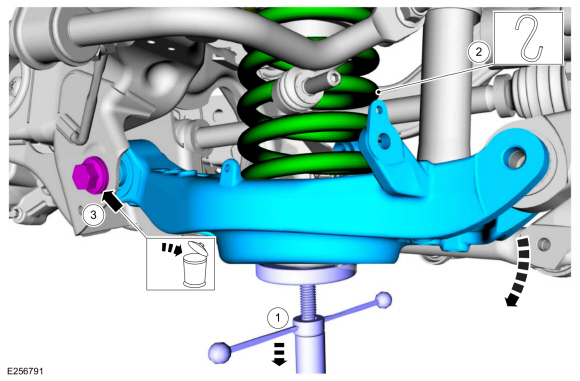
NOTICE: Take extra care when handling a compressed spring.Failure to follow this instruction may result in personal injury.
NOTE: Do not allow the rear spring to fall.
-
Lower the suspension to release the spring compression.
-
Remove the spring by lowering the lower arm and position aside.
-
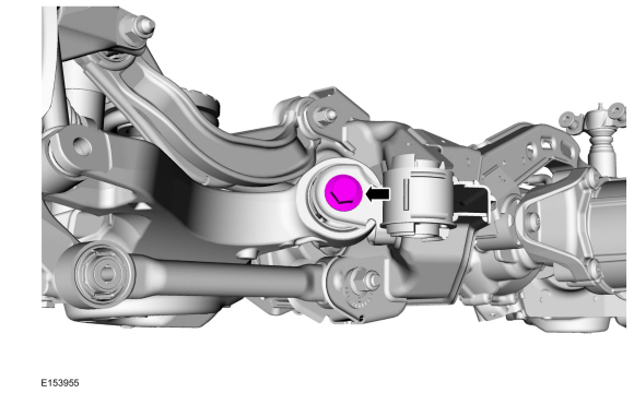
Remove and discard the lower arm-to-frame rearward bolt and remove the lower arm
Use the General Equipment: Vehicle/Axle Stands
-
Lower the suspension to release the spring compression.
 |
Installation
-
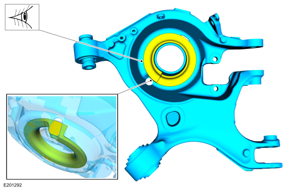
Make sure that the lower spring seat is properly aligned.
 |
-
NOTE: Hold spring in place while installing lower arm.
-
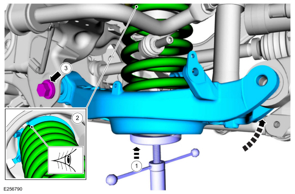
NOTE: Before tightening the lower arm bolt, use a jackstand to raise the rear suspension to ride height
Position the jackstand under the lower arm and raise the lower arm into position.
Use the General Equipment: Vehicle/Axle Stands
-
NOTE: Make sure the upper spring seat is properly positioned on the upper spring mount.
Install the spring into the upper and lower spring seat.
-
NOTE: Only tighten the bolt finger tight at this stage.
Install the new lower arm-to-frame rearward bolt.
-
 |
-
NOTE: Only tighten the bolt finger tight at this stage.
Install the new lower arm-to-frame rearward bolt.
 |
-
NOTE: Only tighten the bolt and nut finger tight at this stage.
-
Position the wheel knuckle to the lower arm and install the new lower arm-to-wheel knuckle bolt.
-
Position the rear stabilizer bar link and install the new rear stabilizer bar link lower nut.
-
Position the wheel knuckle to the lower arm and install the new lower arm-to-wheel knuckle bolt.
 |
-
NOTE: Only tighten the bolts finger tight at this stage.
-
Install the new toe link-to-wheel knuckle bolt.
-
Install the new lower arm vertical link lower bolt.
-
Install the new toe link-to-wheel knuckle bolt.
 |
-
Suspension at curb height.
Use the General Equipment: Vehicle/Axle Stands
 |
-
NOTICE: Tighten the suspension bushing fasteners with the suspension loaded or with the weight of the vehicle resting on the wheels and tires, otherwise incorrect clamp load and bushing damage may occur.
Tighten the new lower arm-to-frame rearward bolt.
Torque: 184 lb.ft (250 Nm)
 |
-
NOTICE: Tighten the suspension bushing fasteners with the suspension loaded or with the weight of the vehicle resting on the wheels and tires, otherwise incorrect clamp load and bushing damage may occur.
Tighten the new lower arm-to-frame forward bolt.
Torque: 166 lb.ft (225 Nm)
 |
-
NOTICE: Tighten the suspension bushing fasteners with the suspension loaded or with the weight of the vehicle resting on the wheels and tires, otherwise incorrect clamp load and bushing damage may occur.
-
Tighten the new lower arm-to-wheel knuckle bolt.
Torque: 203 lb.ft (275 Nm)
-
Tighten the new rear stabilizer bar link lower nut.
Torque: 85 lb.ft (115 Nm)
-
Tighten the new lower arm-to-wheel knuckle bolt.
 |
-
NOTICE: Tighten the suspension bushing fasteners with the suspension loaded or with the weight of the vehicle resting on the wheels and tires, otherwise incorrect clamp load and bushing damage may occur.
-
Tighten the new toe link-to-wheel knuckle bolt.
Torque: 129 lb.ft (175 Nm)
-
Tighten the new lower arm vertical link lower bolt.
Torque: 129 lb.ft (175 Nm)
-
Tighten the new toe link-to-wheel knuckle bolt.
|
-
Install the new rear shock absorber lower bolts.
Torque: 35 lb.ft (48 Nm)
 |
-
If equipped.
Position the rear shock absorber wire harness and clip the harness retaining clips into place.
 |
-
If equipped.
Position the rear height sensor arm bracket and install the rear height sensor arm bracket bolt.
Torque: 177 lb.in (20 Nm)
|
-
Install the wheel and tire.
Refer to: Wheel and Tire (204-04A Wheels and Tires, Removal and Installation).
-
Check and if necessary adjust rear camber.
Refer to: Rear Camber Adjustment (204-00 Suspension System - General Information, General Procedures).
-
Calibrate the suspension system. Connect the scan tool
and carry out the Ride Height Calibration routine. Follow the scan tool
directions.

 Lower Arm Vertical Link. Removal and Installation
Special Tool(s) /
General Equipment
Vehicle/Axle Stands
Removal
NOTICE:
Suspension fasteners are critical parts that affect the
performance of vital components and systems...
Other information:
Lincoln Nautilus 2018-2026 Service Manual: Rear Center Seatbelt Buckle. Removal and Installation
Removal NOTE: Removal steps in this procedure may contain installation details. Remove the rear seat cushion. Refer to: Rear Seat Cushion (501-10B Rear Seats, Removal and Installation). Remove the bolt and the rear center seatbelt buckle...
Lincoln Nautilus 2018-2026 Service Manual: Module Configuration - System Operation and Component Description. Description and Operation
System Operation Overview Over the Air (OTA) Programming Over-the-Air updates allow for vehicle system software to be updated wirelessly over Wi-Fi (both private and or public Wi-Fi connection) and or the vehicle cellular network. Over-the-Air updates occur on a rolling basis...
Categories
- Manuals Home
- 1st Generation Nautilus Owners Manual
- 1st Generation Nautilus Service Manual
- Auto Hold
- Switching the Lane Keeping System On and Off. Switching the Lane Keeping System Mode
- Normal Scheduled Maintenance
- New on site
- Most important about car
Replacing the Rear Wiper Blades
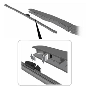
Note: Do not hold the wiper blade to lift the wiper arm.
Remove the wiper blade.