Lincoln Nautilus: Instrumentation, Message Center and Warning Chimes / Message Center - System Operation and Component Description. Description and Operation
System Operation
System Diagram

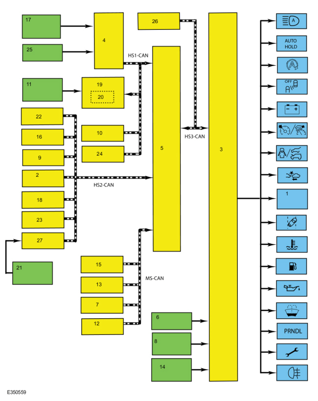
| Item | Description |
|---|---|
| 1 | Message center display |
| 2 | ABS module |
| 3 | IPC |
| 4 | BCM |
| 5 | GWM |
| 6 | Washer fluid level switch |
| 7 | SODR |
| 8 | Fuel pump and sender unit |
| 9 | IPMA |
| 10 | PAM |
| 11 | Engine oil pressure sensor |
| 12 | HVAC module |
| 13 | SODL |
| 14 | Fuel level sensor |
| 15 | DSM |
| 16 | PSCM |
| 17 | Door/hood/liftgate ajar switch |
| 18 | RCM |
| 19 | PCM |
| 20 | TCM |
| 21 | LH upper steering wheel switch |
| 22 | VDM |
| 23 | GSM |
| 24 | HCM |
| 25 | Brake fluid level switch |
| 26 | APIM |
| 27 | SCCM |
Network Message Chart
Module Network Input Messages - IPC
| Broadcast Message | Originating Module | Message Purpose |
|---|---|---|
| Adaptive cruise control warning request | IPMA | Input used to display the adaptive cruise control warning messages. |
| Ambient air temperature | PCM | Filtered input used to control the frost warning RTT indicator. |
| Ambient air temperature filtered | PCM | Filtered input used to display the outside air temperature. |
| Auto high beam indication | IPMA | Input used to control the auto high beam RTT indicator and warning message. |
| Auto hold mode indicator | ABS module | Input used to control the auto hold RTT indicator. |
| AWD service required | AWD module | Input used for the AWD component to control the powertrain malfunction (wrench) RTT indicator. |
| AWD status display | AWD module | Input used to display the AWD messages. |
| Battery low state of charge | BCM | Input used to control the charging system RTT indicator, check charging system warning message and load shed messages. |
| Battery shed level request | BCM | Input used to control the PRNDL based on the battery load shed state. |
| Body service required request | BCM | Input used for the BCM controlled system faults input to control the powertrain malfunction (wrench) RTT indicator. |
| Brake fluid level low message request | BCM | Input used to display the low brake fluid level message center message. |
| Brake (red) warning indicator request | ABS module | Input used to display the message center brake system messages and to display the electronic parking brake message center warning messages. |
| Camera status | IPMA | Input used to display the lane keeping system camera malfunction message. |
| Check fuel fill inlet message request | PCM | Input used to display the check fuel fill inlet message. |
| Child lock message request | BCM | Input used to display the child lock system fault message. |
| Compass direction | APIM | Input used to display the current compass heading. |
| Cross traffic alert left status | SODL | Input used to control the blind spot information system RTT indicator and message center messages. |
| Cross traffic alert right status | SODR | Input used to control the blind spot information system RTT indicator and message center messages. |
| Cruise control set speed display | PCM | Input used to indicate the cruise control set speed displayed in the message center. |
| Cruise control status | PCM | Input used to control the cruise control RTT indicator and message display based on the system status. |
| Cruise control override | PCM | Input used to control the adaptive cruise control set speed display when the cruise control is overridden by the driver. |
| Driver door ajar status | BCM |
|
| EPAS failure | PSCM | Input used to control the service power steering message display. |
| Engine coolant temperature data | PCM | Input used to control the over-temperature RTT indicator and engine over-temperature warning message. |
| Engine idle shutdown status | PCM | Input used to control the engine idle shutdown warning messages. |
| Engine oil life | PCM | Input used for the oil life display. |
| Engine oil pressure warning indicator status | PCM | Input used to control the engine oil pressure RTT indicator and the low engine oil pressure message center warning. |
| Engine overheat indication request | PCM | Input used to control the engine over-temperature RTT indicator and engine over-temperature warning message. |
| Engine rpm data | PCM |
|
| Engine service required request | PCM | Input used for the powertrain Electronic Throttle Control (ETC) component to control the powertrain malfunction (wrench) RTT indicator. |
| Forward collision warning message request | IPMA | Input used to display the forward collision malfunction messages. |
| Front passenger detect status | RCM | Input used to display the front passenger seat object entrapped message. |
| Fuel flow volume display | PCM | Input used to calculate the Average Fuel Economy (AFE) and DTE . |
| Hill start assist mode | ABS module | Input used to display the hill start status messages. |
| Ignition key type | BCM | Input used to calculate the Average Fuel Economy (AFE) and DTE for MyKey® settings. |
| Ignition status | BCM |
|
| Immobilizer message request | BCM | Input used to display the passive entry and push button start messages (no key detected, place key in backup slot, restart now, key programming and accessory power active). |
| Keycode status | BCM | Input used to display the factory keypad code when requested by the driver. |
| Lane keeping system status display | IPMA | Input used to control the lane keeping system off RTT indicator and the lane keeping system fault messages. |
| Lane keeping system hands off display | IPMA | Input used to display the lane keeping system hands off the steering wheel warning message. |
| Left rear door ajar status | BCM | Input used for the door ajar RTT indicator and the left rear door ajar warning message. |
| Liftgate ajar status | BCM | Input used for the door ajar RTT indicator and the liftgate ajar warning message. |
| Memory feedback status | DSM | Input used to display the memory set feature deny and recall messages. |
| Odometer count | PCM | Input used to display the odometer and to calculate the Average Fuel Economy (AFE) and DTE . |
| Parking aid front status | PAM | Input used to display the parking aid malfunction message. |
| Parking aid rear status | PAM | Input used to display the parking aid malfunction message. |
| Parking brake chime request | BCM | Input used to display the message center brake system messages. |
| Passenger door ajar status | BCM | Input used for the door ajar RTT indicator and the passenger door ajar warning message. |
| Perimeter alarm chime request | BCM | Input used to display the perimeter alarm message when the vehicle is entered before deactivating the perimeter alarm. |
| Power pack status | PCM | Input used to control the engine on warning message (push button start). |
| Powertrain cooling message request | PCM | Input used to display the reduced power to cool the engine on the Gasoline Turbo Direct Injection (GTDI) engines. |
| Powertrain driver mode status | PCM | Input used to control the tow haul RTT indicator. |
| Remote start status | BCM | Input used to control the remote start informational message display. |
| Right rear door ajar status | BCM | Input used for the door ajar RTT indicator and the right rear door ajar warning message. |
| Side obstacle detect status-left | SODL | Input used to control the blind spot information system RTT indicator and message center messages. |
| Side obstacle detect status-right | SODR | Input used to control the blind spot information system RTT indicator and message center messages. |
| Starting system fault message request | PCM | Input used to display starting system messages. |
| Stability-traction control chime request | ABS module |
|
| Steering wheel lock message request | BCM | Input used to control the steering wheel lock system messages. |
| Steering wheel message center switch data | SCCM | Input used to control the message center navigation and functions. |
| Stop-start message request | PCM | Input used to display the auto stop-start message center messages. |
| Stop-start standby indicator | PCM | Input used to control the auto stop-start RTT indicator. |
| Tire pressure system status | BCM | Input used to display specific tire training instructional messages and TPMS fault messages. |
| Trailer sway status | ABS | Input used to display the trailer sway event in progress message. |
| Transmission gear display | PCM | Input used to control the PRNDL display. |
| Transmission message request | PCM | Input used to display the transmission warning messages. |
| Transmission shift mode display | PCM |
|
| Transmission service required | PCM | Input used for the transmission component to control the powertrain malfunction (wrench) RTT indicator. |
| Transport mode | BCM | Input used to indicate whether the vehicle is set in factory mode or transport mode, display the PRNDL not in park warning message and to display the appropriate message and power down items such as the PRNDL at key off to conserve the battery. |
| Vehicle dynamics SOS | ABS | Input used to control the spin-out detected message. |
| Vehicle speed | PCM |
|
Module Network Input Messages - PCM
| Broadcast Message | Originating Module | Message Purpose |
|---|---|---|
| Engine oil life data reset | IPC | Input used to reset the oil life. |
Message Center Displays
Compass Display
The compass can be displayed as a virtual compass along with the 1 or 2 character display. The IPC receives the compass direction message from the APIM over the HS-CAN3 .
DTE /Average Fuel Economy (AFE)
The DTE is calculated in the IPC using the Running Average Fuel Economy (RAFE), which is the fuel economy over the last 480 km (300 miles), and the fuel level input from the fuel sender(s) to determine how many miles the vehicle can be driven based on the remaining fuel in the tank. The DTE can vary in the short term by up to 50 miles, but is usually within 10 miles. Even if the fuel economy is relatively constant, the DTE can be off over a 50 mile range by -24% to +38%. The DTE display and the fuel gauge both use the fuel level input from the fuel tank to provide their respective functions. If the fuel gauge doesn't function correctly, both the fuel gauge and the DTE display are affected.
The IPC defaults to a preset baseline mpg when the battery is initially connected and changes based on driving habits and conditions.
NOTE: The actual DTE can be higher or lower than the DTE displayed in the message center due to changes in driving conditions. It is important to understand how the DTE is calculated and the factors that impact the DTE display when determining how to address any DTE concerns.
Since the DTE is calculated and averaged over a longer period of time (480 km [300 miles]), varying driving conditions can have a significant impact on the current or short term DTE as opposed to the displayed DTE . This difference often leads to customer complaints of incorrect or invalid DTE . The following list provides some (not all) of the driving conditions that may lead to an incorrect or fluctuating DTE concern:
- Changing between towing/not towing
- Changing driving between city and highway
- Allowing the vehicle to idle for long periods of time
- Using the remote start feature frequently to allow the vehicle to warm up, particularly when parked on a grade
- Parking or driving on grades
- Inconsistent use of gasoline or E85 fuels
- Over-fueling or not filling the tank completely (partial refueling)
To better illustrate the affects of how driving conditions can affect DTE , refer to the following 2 examples. The first example below illustrates how the following observations are normal and expected since the low fuel reminder is triggered from a fuel volume and not from a fixed distance to empty.
- If while driving, the low fuel reminder (low fuel indicator and low fuel warning message) displays when the DTE equals 94.4 km (59 miles) and the driver adds 11.36 L (3 gallons) of fuel, the new DTE may become 124.8 km (78 miles). After continued driving, the low fuel reminder may now display when the DTE equals 83.2 km (52 miles).
The second example (below) illustrates what occurs when idling on an incline. In this example, the customer should be made aware of how the condition will correct after a few minutes of idling on a level surface.
- If the customer stops and parks the vehicle on an incline in a driveway, then in the morning remote starts the vehicle, allowing the engine to idle, the DTE may now equal 184 km (115 miles). As the customer drives, the low fuel reminder displays when the DTE equals 148.8 km (93 miles). Finally, after 5 more minutes of driving, the DTE is back to 80 km (50 miles).
Distance Alert
The distance alert display illuminates when the system detects the vehicle is rapidly approaching another vehicle, and warns the driver of a risk of possible collision. The distance alert display illuminates and flashes in red in the message center when a short distance to the vehicle or object in front is detected.
The IPC receives the forward distance alert warning request from the GWM over the HS-CAN3 . The GWM receives the forward distance alert warning request from the IPMA over the HS-CAN2 .
Engine Oil Life Message Center Display
The IPC provides message center messages to inform the driver about the oil life status and when an oil change is required. The duration of the interval between oil changes is calculated in the PCM and varies due to driving conditions. The PCM assumes a base mileage of 16,090 km (10,000 mi) or 1 year for normal driving. However, this number is adjusted down for conditions such as high engine temperature, high engine rpm, use of flex fuel and low engine oil level on some vehicles. The PCM calculates and provides the engine oil life percent message to the IPC . The engine oil change minder can be reset at any time by the driver.
The PCM receives the engine oil life data reset request from the GWM over the HS-CAN1 . The GWM receives the engine oil life data reset request from the IPC over the HS-CAN3 .
The IPC receives the engine oil life message from the GWM over the HS-CAN3 .
The GWM receives the engine oil life message from the PCM over the HS-CAN1 .
Factory-Transport Mode Display
During vehicle build, some modules, such as the IPC and the BCM , are set in factory mode. While in the factory mode the IPC displays FACTORY MODE CONTACT DEALER in the message center. If the vehicle is set in factory mode, the system does not automatically exit the mode and must be manually set to either the transport or normal operation mode.
When the vehicle build is complete, the vehicle is set to transport mode. While in transport mode, the IPC displays TRANSPORT MODE CONTACT DEALER in the message center. Transport mode is used to reduce the drain on the battery during longer periods where the vehicle is not used. Various systems may be altered or are disabled when in the transport mode. The vehicle automatically reverts to normal operation mode after being driven 80 km (50 mi).
The IPC receives the transport mode message from the GWM over the HS-CAN3 . The GWM receives the transport mode message from the BCM over the HS-CAN1 .
Lane Keeping System
The lane keeping system combines the lane keeping alert and lane keeping aid systems. The lane keeping alert system alerts the driver of unintentional drifting outside of the lane and the lane keeping aid system corrects the vehicle steering to keep the vehicle in the center of the lane. The IPC provides a lane keeping display as an overhead view of the vehicle in the middle of a lane with right and left lane markers to indicate the vehicle position with relation to the lane markings as well as overlay or popup messages to alert the driver when they are drifting out of their lane or need to place their hands on the steering wheel. The lane markers change color to indicate the condition associated with a specific condition and action or warning as controlled by the lane keeping system. The IPC also provides a lane keeping system message center off indicator to inform the driver that the lane keeping system is turned off. When the lane keeping system is turned off, the IPC turns on the lane keeping system RTT and turns off the lane keeping system display.
The IPC receives the camera status, lane keeping system status display and the lane keeping system hands off display messages from the GWM over the HS-CAN3 .
The GWM receives the lane keeping system switch and the lane keeping system hands off display messages from the IPMA over the HS-CAN2 .
The GWM receives the camera status message from the IPMA over the HS-CAN2 .
MyKey® Function Displays
The IPC provides message center displays for the MyKey® feature. MyKey® displays are controlled through the IPC software based on the MyKey® settings configured through the message center and the type of key in use (MyKey® or administrator key). The MyKey® function also uses other messages received by the IPC for other indications such as vehicle speed for speed limiter displays.
Odometer
The IPC receives the odometer count message from the GWM over the HS-CAN3 . The GWM receives the odometer count from the PCM over the HS-CAN1 . The IPC monitors the odometer count input from the GWM and commands the odometer with a digital display in the message center.
TPMS
The IPC provides a message center display showing each tire on a vehicle image to indicate specific tire pressures.
The IPC receives the tire pressure system status message from the GWM over the HS-CAN3 . The GWM receives the tire pressure system status message from the BCM over the HS-CAN1 .
Outside Air Temperature
The Ambient Air Temperature (AAT) sensor is hardwired to the PCM through separate input and return circuits. The PCM provides a reference voltage to the Ambient Air Temperature (AAT) sensor and monitors the change in voltage resulting from changes in resistance as determined by outside air temperature.
The PCM sends the ambient air temperature data to the GWM through the HS-CAN1 . The GWM sends the ambient air temperature message to the HVAC module over the MS-CAN . The HVAC module filters the data and sends the ambient air temperature filtered data back to the GWM over the MS-CAN . The GWM sends the ambient air temperature filtered message to the IPC over the HS-CAN3 .
The HVAC module is programmed to update the messaged outside temperature data at different rates depending on several criteria to prevent false temperature displays due to a condition known as heat soaking. Heat soaking is where the outside air temperature is hotter in the location of the Ambient Air Temperature (AAT) sensor than the actual outside air temperature.
The outside air temperature display update strategy requires a starting temperature to update from. This starting temperature is controlled based on the length of time the engine is off and the engine temperature. When the engine has been off for longer than 6 hours, the update strategy begins with the unfiltered ambient air temperature input to the PCM . If the engine has been off for less than 6 hours, and the engine coolant temperature is less than 49° C (120° F), the update strategy begins with the filtered ambient air temperature equal to the unfiltered ambient air temperature. If the engine has been off for less than 6 hours, and the engine coolant temperature is greater than 49° C (120° F), the update strategy begins at the stored previous outside air temperature value.
When the sensed outside temperature rises and the vehicle speed is above 33 km/h (21 mph), the outside air temperature display updates after approximately 90 seconds. As the vehicle speed increases, the outside air temperature display updates at a faster rate that is proportional to the increase in vehicle speed. Once the vehicle speeds exceeds 81 km/h (50 mph), the display updates without any delay. If the vehicle speed drops below 33 km/h (21 mph), the update delays reset. When the sensed outside temperature drops, the display updates more quickly following the drop experienced by the Ambient Air Temperature (AAT) sensor.
RTT Indicators
Auto High Beam
The message center provides the auto high beam RTT to inform the driver the auto high beam function is turned on and the high beam status may automatically change. The IPC receives the auto high beam indication request from the GWM over the HS-CAN3 . The GWM receives the high beam indication request from the IPMA over the HS-CAN2 .
Auto Hold
The message center provides the auto hold RTT to indicate to the driver the state of the auto hold feature. The auto hold feature holds a vehicle stationary once the vehicle has come to a stop using the brakes, allowing the driver the convenience of removing his or her foot from the brake pedal. The IPC receives the auto hold mode indicator request message from the GWM over the HS-CAN3 . The GWM receives the auto hold mode indicator request message from the ABS module over the HS-CAN2 .
Auto Stop/Start
The auto stop/start indicator informs the driver of the following states:
- Solid green - the auto stop/start feature has temporarily turned off the engine.
- Solid amber - a stop/start system concern exists.
- Flash in either green or amber - system state as determined by the PCM .
The IPC receives the stop/start standby request from the GWM over the HS-CAN3 . The GWM receives the auto stop/start standby request from the PCM over the HS-CAN1 .
Blind Spot Monitoring System (BLIS®) Off
The message center provides a RTT indicator to inform the driver that the BLIS is turned off. The IPC receives the cross traffic alert left status, cross traffic alert right status, side obstacle detect status-left and side obstacle detect status-right messages from the GWM over the HS-CAN3 . The GWM receives the cross traffic alert left status, cross traffic alert right status, side obstacle detect status-left and side obstacle detect status-right messages from the SODL and SODR over the MS-CAN .
Charging System
The message center provides a charging system RTT indicator along with message displays indicating the status of the charging system. When a fault is present in the charging system, the BCM sends the battery low state of charge message to display message center warning messages and the charging system RTT indicator.
The IPC receives the battery low state of charge message from the GWM over the HS-CAN3 . The GWM receives the battery low state of charge message from the BCM over the HS-CAN1 .
Cruise Control
The IPC uses the following messaged inputs to control the cruise control RTT indicator:
- cruise control status
- cruise control set speed display
- cruise control override
The IPC receives the cruise control messages from the GWM over the HS-CAN3 . The GWM receives the cruise control messages from the PCM over the HS-CAN1 .
Door, Hood Or Liftgate Ajar
The message center provides a door ajar RTT along with message displays to indicate the status of the doors, hood and liftgate. The BCM monitors each of the ajar inputs (driver, passenger, left rear, right rear, hood and liftgate) and sends a door ajar status (driver door ajar status, passenger door ajar status, left rear door ajar status, right rear door ajar status, hood ajar status or liftgate ajar status) message to the GWM over the HS-CAN1 . The IPC receives the driver door ajar status, passenger door ajar status, left rear door ajar status, right rear door ajar status, hood ajar status or liftgate ajar status messages from the GWM over the HS-CAN3 to display the specific ajar RTT and corresponding warning message.
Engine Over-Temperature
The message center provides a message center warning indicator to alert the driver the engine is over temperature. The IPC receives the engine overheat indication request and the engine coolant temperature data from the GWM over the HS-CAN3 . The GWM receives the engine overheat indication request and the engine over-temperature message from the PCM over the HS-CAN1 .
Lane Centering Assist
The IPC provides the lane centering assist RTT indicator to inform the driver the lane centering assist system has been turned on. The RTT indicator illuminates green when the system is on, amber to indicate a concern and is gray when the system is not available. Lane centering assist can only be enabled when the adaptive cruise control system is activated.
Lane Keeping System Off
The IPC provides the lane keeping system off RTT to indicate the lane keeping system has been turned off or is disabled due to a fault condition. The IPC receives the lane keeping system status display message from the GWM over the HS-CAN3 . The GWM receives the lane keeping system status display message from the IPMA over the HS-CAN2 .
Low Engine Oil Pressure
The IPC uses the engine oil pressure warning indicator status request and engine rpm data to control the low engine oil pressure indicator. The engine oil pressure switch is hardwired to the PCM . The PCM provides the engine oil pressure warning indicator status request and the engine rpm data to the GWM over the HS-CAN1 . The GWM provides the engine oil pressure warning indicator status request and engine rpm data to the IPC over the HS-CAN3 . The IPC requires engine rpm above 400 rpm before the message center displays the low engine oil pressure RTT indicator.
Low Fuel
To supplement the fuel gauge indication, the IPC provides the low fuel message center warning indicator. When the fuel level reaches approximately 120 km (75 miles) for MyKey® users and 80 km (50), 40 km (25), 20 km (12) and 0 km (0 miles) for administrator key users, the IPC turns on the low fuel message center warning indicator.
Low Washer Fluid Level
The low washer fluid level switch is hardwired to the IPC through a single signal circuit and is grounded through a separate ground circuit. The IPC provides a reference voltage to the washer fluid level switch. When the washer fluid is low, the washer fluid level switch closes to ground, pulling the reference voltage low. When the IPC detects the washer fluid input pulled low and illuminates the low washer fluid level RTT indicator.
Powertrain Malfunction (Wrench)
The message center provides a powertrain malfunction (wrench) RTT indicator to indicate transmission, Electronic Throttle Control (ETC), AWD and BCM concerns.
The IPC receives all the required messages from the GWM over the HS-CAN3 .
The GWM receives the body service required message from the BCM over the HS-CAN1 .
The GWM receives the AWD service required message from the AWD module over the HS-CAN2 .
The GWM receives the engine service required and transmission service required messages from the PCM over the HS-CAN1 .
PRNDL And SelectShift®
The SelectShift® display indicates to the driver which gear is currently selected when the transmission is in the SelectShift® mode. When the transmission is in SelectShift® mode, the gear number is displayed in the SelectShift® display area.
For additional information related to the SelectShift® features, refer to the Owner's Literature.
The IPC uses the following messages to control the PRNDL/progressive range select and SelectShift® indication.
- Battery shed level request
- Igntion status
- Transport mode
- Transmission gear display
- Transmission shift mode display
- Vehicle speed
The IPC receives all required messages from the GWM over the HS-CAN3 .
The GWM receives the transmission gear position, transmission shift mode display and vehicle speed messages from the PCM over the HS-CAN1 and the ignition status, transport mode and battery shed level request messages from the BCM over the HS-CAN1 .
Warning Messages
Adaptive Cruise Control
The message center provides messages explaining the need for driver intervention and system status. The adaptive cruise control messages are supplemental to the cruise control RTT and the adaptive cruise control warning chime. The IPC receives the adaptive cruise control warning request, adaptive cruise control message center request and adaptive cruise control service required messages from the GWM over the HS-CAN3 . The GWM receives the adaptive cruise control warning request, adaptive cruise control message center request and adaptive cruise control service required messages from the CCM over the HS-CAN2 .
AWD
The message center provides message center messages to inform the driver of the status of the AWD . The IPC receives the AWD status display message from the GWM over the HS-CAN3 . The GWM receives the AWD status display message from the AWD module over the HS-CAN2 .
Auto High Beam
The message center provides the auto high beam fault message to inform the driver of a fault with the auto high beam system. The IPC receives the adaptive headlamp fault status message from the GWM over the HS-CAN3 . The GWM receives the adaptive headlamp fault status message from the IPMA over the HS-CAN2 .
Auto Hold
The message center provides messages indicating the status of the auto hold feature and to provide instruction to the driver about the auto hold feature operation. The ABS module sends the auto hold message request to the GWM over the HS-CAN2 . The GWM sends the auto hold message request to the IPC over the HS-CAN3 .
Auto Stop-Start
The message center provides messages explaining the need for driver intervention and system status. The IPC receives the stop/start message request from the GWM over the HS-CAN3 . The GWM receives the stop/start message request from the PCM over the HS-CAN1 .
BLIS /Cross Traffic Alert (CTA)
The message center provides messages indicating the reason for the BLIS /Cross Traffic Alert (CTA) fault. The IPC receives the side obstacle sensor status-left and side obstacle sensor status-right messages from the GWM over the HS-CAN3 . The GWM receives the side obstacle sensor status-left and side obstacle sensor status-right messages from the SODL and SODR , respectively, over the MS-CAN .
Brake System
The message center provides brake system messages for the following concerns and status:
- Low brake fluid level
- Parking brake applied status
- ABS concerns that display along with the brake warning indicator operation
When the parking brake is applied, the BCM sends the parking brake chime request to the GWM over the HS-CAN1 . The GWM gateways the message to the IPC over the HS-CAN3 to illuminate the brake warning indicator and turn on the parking brake applied message in the message center.
When a low brake fluid level condition exists, the BCM sends the brake fluid level low message request to the GWM over the HS-CAN1 . The GWM gateways the message to the IPC over the HS-CAN3 to illuminate the brake warning indicator and turn on the brake fluid level low message in the message center.
When an ABS or parking brake system concern exists, the ABS module sends the brake (red) warning indicator request message to the GWM over the HS-CAN2 . The GWM sends the brake (red) warning indicator request message to the IPC over the HS-CAN3 to illuminate the ABS warning indictor and to turn on the check brake system message center warning display.
Charging System
The message center provides a warning message indicating the status of the charging system. When a fault is present in the charging system, the BCM sends the battery low state of charge message to the GWM over the HS-CAN1 . The IPC receives the battery low state of charge message from the GWM over the HS-CAN3 .
Check Fuel Fill Inlet
The message center provides a check fuel fill inlet message to warn the driver there is a problem with the fuel fill inlet pipe resulting in a significant evaporative emission leak following vehicle refueling. The IPC receives the check fuel fill inlet message request from the GWM over the HS-CAN3 . The GWM receives the check fuel fill inlet message request from the PCM over the HS-CAN1 .
Door, Hood or Liftgate Ajar
The message center provides door, hood and liftgate ajar warnings to indicate the status of the doors, hood and liftgate. The IPC receives the driver door ajar, passenger door ajar, left rear door ajar, the right rear door ajar status, hood ajar status and liftgate ajar status messages from the GWM over the HS-CAN3 . The GWM receives the driver door ajar, passenger door ajar, left rear door ajar, the right rear door ajar status, hood ajar status and liftgate ajar status messages from the BCM over the HS-CAN1 . The BCM monitors each of the ajar inputs and sends the specific door ajar status message to the IPC to display the ajar warning indicator and corresponding warning message.
Electronic Park Brake
The message center provides messages to indicate the status of the electronic parking brake system. The messages displayed are a combination of informational messages, warning and system fault messages. The IPC uses the following messages to display the applicable message center message.
- Electronic park brake message request
- Electronic park brake (red) indicator request
- Brake (red) warning indicator request
- Brake fluid level low message request
The IPC receives all messages required to display the electronic park brake messages from the GWM over the HS-CAN3 .
The GWM receives the parking brake message request and the brake (red) warning indicator request from the ABS module over the HS-CAN2 .
The GWM receives the brake fluid level low message request from the BCM module over the HS-CAN1 .
EPAS
The message center provides a message center message to indicate there is an EPAS system concern. When a fault exists in the EPAS , the PSCM sends a request to the IPC through the GWM .
The IPC receives the EPAS failure message from the GWM over the HS-CAN3 .
The GWM receives the EPAS failure message from the PSCM over the HS-CAN2 .
Engine On
The message center provides the engine on warning message to inform the driver they are exiting the vehicle when the engine is running. The IPC uses multiple inputs to determine the vehicle is stopped and the driver is preparing to exit the vehicle. The messages required to control the engine on warning message are as follows:
- Driver door ajar status
- Power pack status
- Transmission shift mode display
- Vehicle speed
The IPC receives all required messages from the GWM over the HS-CAN3 .
The GWM receives the driver door ajar status from the BCM over the HS-CAN1 .
The GWM receives the power pack status, transmission shift mode display and the vehicle speed messages from the PCM over the HS-CAN1 .
Engine Over-Temperature
The message center provides the engine coolant over-temperature warning message to supplement the engine over-temperature RTT and alert the driver the engine is over temperature. The IPC receives the engine overheat indication request and the engine coolant temperature data from the GWM over the HS-CAN3 . The GWM receives the engine overheat indication request and the engine over-temperature message from the PCM over the HS-CAN1 .
Exterior Lighting Inoperative
The message center provides an exterior lighting inoperative message when a fault is detected in the lighting connections or a bulb is loose or inoperative. The BCM sends an exterior lighting fault message to the GWM over the HS-CAN1 . The GWM sends the exterior lighting fault message to the IPC over the HS-CAN3 .
Forward Collision
The message center provides the forward collision warning messages to inform the driver of the forward collision status. The IPC receives the forward collision warning message request from the GWM over the HS-CAN3 . The GWM receives the forward collision warning message request from the IPMA over the HS-CAN2 .
Hill Start Assist
The message center provides a message indicating the hill start assist feature is not available due to a fault in the ABS . When a fault is detected and the hill start assist is disabled, the ABS module sends the hill start assist mode message to the GWM over the HS-CAN2 . The GWM sends the hill start assist mode message to the IPC over the HS-CAN3 .
Keypad Factory Code
The message center can display the original keypad factory code when
requested. The IPC receives the keypad code message from the GWM over
the HS-CAN3 . The GWM receives the keypad code message from the BCM over
the HS-CAN1 . For information on how to retrieve the factory code,
Refer
to: Handles, Locks, Latches and Entry Systems - System Operation and
Component Description (501-14 Handles, Locks, Latches and Entry Systems,
Description and Operation).
Lane Keeping System
The message center provides a warning message for the lane keeping alert and system fault messages for the over all lane keeping system. The IPC receives all required messages from the GWM over the HS-CAN3 . The GWM receives the lane keeping system hands off display message, the lane keeping system status display and the camera status message from the IPMA over the HS-CAN2 .
Load Shed
The message center provides load shed messages to inform the driver to use less options to conserve battery voltage. The IPC receives the battery low state of charge message from the GWM over the HS-CAN3 . The GWM receives the battery low state of charge message from the BCM over the HS-CAN1 .
Low Engine Oil Pressure
The message center uses the low engine oil pressure warning message as a supplement to the low engine oil pressure RTT indicator to inform the driver when low engine oil pressure exists. The engine oil pressure switch is hardwired to the PCM . The PCM provides the engine oil pressure warning indicator status request and the engine rpm data to the GWM over the HS-CAN1 . The GWM provides the engine oil pressure warning indicator status request and engine rpm data to the IPC over the HS-CAN3 . The IPC requires engine rpm above 400 rpm before the message center displays the low engine oil pressure warning message.
Memory Seat Status
The message center provides memory seat status messages to provide the driver confirmation that memory position storing was successful and that recalling a memory position cannot be recalled while driving the vehicle. The IPC receives the memory feedback status message from the GWM over the HS-CAN3 . The GWM receives the memory feedback status message from the DSM over the MS-CAN .
OCS Blocked
The message center provides an OCS sensor is blocked and restricting correct functioning. The IPC receives the front passenger detect status message from the GWM over the HS-CAN3 . The GWM receives the front passenger detect status message from the RCM over the HS-CAN2 .
Engine Oil Life
The message center provides messages to inform the driver about the engine oil life status, engine oil life reset status and when an engine oil change is required. The duration of the interval between engine oil changes is calculated in the PCM and varies due to driving conditions. The PCM assumes a base mileage of 16,090 km (10,000 mi) or 1 year for normal driving. However, this number is adjusted down for conditions such as high engine temperature, high engine rpm, use of flex fuel and possibly low engine oil level. The PCM calculates and provides the engine oil life percent message to the IPC . The engine oil change minder can be reset at any time by the driver.
The IPC receives the engine oil life message from the GWM over the HS-CAN3 . The GWM receives the engine oil life message from the PCM over the HS-CAN1 .
The PCM receives the engine oil life data reset message from the GWM over the HS-CAN1 . The GWM receives the engine oil life data reset message from the IPC over the HS-CAN3 .
Parking Aid System
The message center provides messages to indicate the status of the parking aid system. The IPC receives the parking aid rear status message from the GWM over the HS-CAN3 . The GWM receives the parking aid rear status message from the PAM over the HS-CAN1 .
PATS And Passive Key And Immobilizer System
The message center provides the starting system fault message to indicate there is a concern with the PATS . The message center provides passive key and immobilizer system messages to indicate the key is in the luggage compartment, the key is left in the vehicle, no key is detected, accessory power is active, to press the brake to start the vehicle or to place the key in the backup slot. The IPC uses the immobilizer message display messaged input from the BCM to display the applicable message center message.
The IPC receives the immobilizer message request from the GWM over the HS-CAN3 .
The GWM receives the immobilizer message request from the BCM over the HS-CAN1 .
Perimeter Alarm Message Display
The message center provides a display to indicate the perimeter alarm has been activated and to start the vehicle to stop the alarm. The IPC receives the perimeter alarm chime request message from the GWM over the HS-CAN3 . The GWM receives the perimeter alarm chime request from the BCM over the HS-CAN1 .
Power Child Lock-Switch Inhibit And Low Key Fob
The message center provides a power child lock warning to inform the driver the child lock feature did not function properly. The power child lock feature is activated through the rear window lockout switch on the driver side master window control switch.
The IPC provides a switch inhibit warning to notify the driver that some switches have been purposely inhibited and are inoperative. For security purposes, interior switches are inhibited by the BCM 20 seconds after the vehicle is electronically locked and prevents someone from using a stick (or other object) through an open window and activating the switch.
The IPC provides a low key fob battery warning to alert the driver the key fob battery needs to be replaced. The low key fob battery warning is not displayed in RUN or START modes if the power child lock warning is active to prevent the BCM from cycling between the two warnings, causing the chime associated with the power child lock warning to repeatedly sound every 4 seconds.
The IPC receives the child lock message request from the GWM over the HS-CAN3 . The GWM receives the child lock message request from the BCM over the HS-CAN1 .
Powertrain Cooling
On vehicles equipped with a Gasoline Turbo Direct Injection (GTDI) engine, the message center provides a message to inform the driver that vehicle performance is reduced to allow the engine to cool. This feature is part of the smart cooling function in the PCM and provides powertrain cooling protection under high ambient temperature conditions.
The IPC receives the powertrain cooling message request from the GWM over the HS-CAN3 . The GWM receives the powertrain cooling message request from the PCM over the HS-CAN1 .
PRNDL Not In Park (Shift To Park)
The message center provides a shift to park message to inform the driver the vehicle is not in PARK (P) under 2 sets of conditions. First, the IPC displays the shift to park message if the selector lever is not in PARK (P), the ignition is OFF and the driver door is open or ajar. Second, the message center displays the shift to park message if the selector lever is not in PARK (P), the ignition is ON or in ACC, the driver door is open or ajar and the brake pedal is not applied with vehicle speed less than 5 km/h (3 mph). The IPC uses multiple messages to control the shift to park message.
The IPC receives all required messages from the GWM over the HS-CAN3 .
The GWM receives the transmission shift mode display and vehicle speed messages from the PCM over the HS-CAN1 .
The GWM receives the driver door ajar status, transport mode and ignition status message from the BCM over the HS-CAN1 .
Remote Start
The message center provides remote start messages to inform the driver the vehicle is in the remote start active state and how to change the state to a drivable state. The remote start message display is active as soon as the vehicle is remote started (that is, the engine is running, but the ignition status is off). Once the driver places the ignition in the RUN state, the IPC carries out it's startup sequence.
The IPC receives the remote start status message from the GWM over the HS-CAN3 . The GWM receives the remote start status message from the BCM over the HS-CAN1 .
Stability-Traction Control
The message center provides stability-traction control system message to indicate the stability-traction control system status or if the stability-traction control system has a fault and requires service.
When the stability-traction control system has been selected off or on, the ABS module sends the stability-traction control on/off message request to the GWM over the HS-CAN2 . The GWM sends the stability-traction control on/off message request to the IPC over the HS-CAN3 .
When a fault condition exists in the stability-traction control system, the ABS module sets a DTC and sends the stability-traction control chime request to the GWM over the HS-CAN2 . The GWM sends the stability-traction control chime request to the IPC over the HS-CAN3 .
Starting System
The message center provides a starting system message to inform the driver of further actions required to start the engine or to explain the reason for the inability to start the engine. The IPC receives the starting system fault message request from the GWM over the HS-CAN3 . The GWM receives the starting system fault message request from the PCM over the HS-CAN1 .
Spinout Detection System
The spinout detection feature activates the hazard indicator to alert other vehicles approaching the vehicle following a spinout, potentially reducing the risk of collision, especially in low visibility weather conditions. A spinout is defined as a slip angle greater than 40 degrees followed by 5 seconds of vehicle at rest.
When a spinout is detected, the system activates the hazard indicator and the IPC displays a message to inform the driver that the hazards have been turned on. The IPC receives the vehicle dynamics SOS message from the GWM over the HS-CAN3 . The GWM receives the vehicle dynamics SOS message from the ABS module over the HS-CAN2 .
TPMS
The message center provides displays to indicate the TPMS sensor training status or a malfunction in the TPMS . The IPC receives the tire pressure system status message from the GWM over the HS-CAN3 . The GWM receives the tire pressure system status message from the BCM over the HS-CAN1 .
Trailer Sway
The message center provides a message to inform the driver to slow the vehicle to reduce trailer sway and bring the trailer under control. The IPC receives the trailer sway status message from the GWM over the HS-CAN3 . The GWM receives the trailer sway status message from the ABS module over the HS-CAN2 .
Transmission
The message center provides warning messages to inform the driver of a transmission malfunction or over-temperature condition. The IPC receives the transmission message request from the GWM over the HS-CAN3 . The GWM receives the transmission message request from the PCM over the HS-CAN1 .
Vehicle Dynamics (Selectable Mode Suspension)
The IPC uses 2 messages to control the vehicle dynamics displays. The first is the driver performance display message, used to control the mode selection and the second is the vehicle dynamic data display message, used to display warning and fault messages. When the driver selects a different mode of operation (comfort, normal or sport), the message center provides a message to indicate the change. When a fault condition exists in the vehicle dynamics system, the message center provides a warning message.
The IPC receives the driver performance display and the vehicle dynamic data display messages from the GWM over the HS-CAN3 . The GWM receives the driver performance display message from the PCM over the HS-CAN1 and the vehicle dynamic data display message from the VDM over the HS-CAN2 .
Component Description
Engine Oil Pressure Sensor (2.0L and 2.7L Engine)
The engine oil pressure sensor is hardwired to the PCM through VREF, signal and return circuits. The PCM provides the sensor voltage supply on the VREF circuit and monitors the change in voltage changes though the signal and return circuits as the engine oil pressure changes.
Low Washer Fluid Level Switch
The low washer fluid switch is hardwired to the IPC through a single signal wire and is grounded to a body ground through a separate circuit. The IPC provides a reference voltage to the low washer fluid level switch. When the washer fluid level is low, the float drops closing the switch and pulling the reference voltage low. When the washer fluid level is high, the float lifts opening the circuit to the IPC and sending the reference voltage high.
Steering Wheel Switch-Message Center
The message center switch is the 5-way portion of the LH steering wheel switch. The message center switch uses different resistance values associated with each specific button (up, down, left, right and OK). The SCCM sends out a reference voltage to the upper LH steering wheel switch on the input circuit and monitors the voltage drops. The voltage drop varies depending upon the resistance of the specific button pressed, providing indication to the SCCM which button is pressed.
 Message Center - Overview. Description and Operation
Overview
The message center is an integral part of the IPC that receives and
acts upon much of the same information that is input and used to
operate the IPC
(gauges, informational indicators, and warning indicators)...
 Warning Chimes - Overview. Description and Operation
Overview
The warning chimes provide the driver with audible warnings that act
as reminders and supplemental alerts to visual IPC indications such as
gauges, indicators and message center warnings...
Other information:
Lincoln Nautilus 2018-2026 Owners Manual: Cooling System Capacity and Specification - 2.7L
Use coolant that meets the defined specification. If you do not use coolant that meets the defined specification, it could result in: Component damage that your vehicle warranty does not cover. Reduced vehicle performance. Capacities Materials ..
Lincoln Nautilus 2018-2026 Service Manual: Stoplamps. Diagnosis and Testing
DTC Charts DTC Chart: BCM Diagnostics in this manual assume a certain skill level and knowledge of Ford-specific diagnostic practices. REFER to: Diagnostic Methods (100-00 General Information, Description and Operation). DTC Description Action B1115:11 High Mounted Stop Lamp Control: Circuit Short to Ground ..
Categories
- Manuals Home
- 1st Generation Nautilus Owners Manual
- 1st Generation Nautilus Service Manual
- USB Ports
- Interior Lamp Function. Adjusting the Instrument Panel Lighting Brightness. Ambient Lighting. Interior Lighting – Troubleshooting
- Changing the 12V Battery
- New on site
- Most important about car
Clearing the Garage Door Opener. Reprogramming the Garage Door Opener. Garage Door Opener Radio Frequencies
Clearing the Garage Door Opener