Lincoln Nautilus: Supplemental Restraint System / Passenger Knee Airbag. Removal and Installation
Removal
 WARNING:
The following procedure prescribes critical repair steps
required for correct restraint system operation during a crash. Follow
all notes and steps carefully. Failure to follow step instructions may
result in incorrect operation of the restraint system and increases the
risk of serious personal injury or death in a crash.
WARNING:
The following procedure prescribes critical repair steps
required for correct restraint system operation during a crash. Follow
all notes and steps carefully. Failure to follow step instructions may
result in incorrect operation of the restraint system and increases the
risk of serious personal injury or death in a crash.
NOTE: Removal steps in this procedure may contain installation details.
-
Refer to: Pyrotechnic Device Health and Safety Precautions (100-00 General Information, Description and Operation).
WARNING:
Before beginning any service procedure in this
manual, refer to health and safety warnings in section 100-00 General
Information. Failure to follow this instruction may result in serious
personal injury.
-
Depower the SRS .
Refer to: Supplemental Restraint System (SRS) Depowering (501-20B Supplemental Restraint System, General Procedures).
-
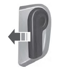
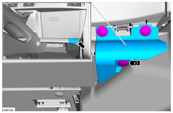
Remove the pin-type retainers and the lower RH trim panel.
 |
-
-
Remove the insulator panel pin-type retainers.
-
Position the insulator panel away from the instrument panel.
-
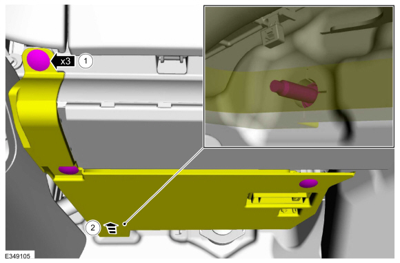
Remove the insulator panel pin-type retainers.
 |
-
Remove the insulator panel.
-
Disconnect the electrical connector.
-
Disconnect the electrical connector.
 |
-
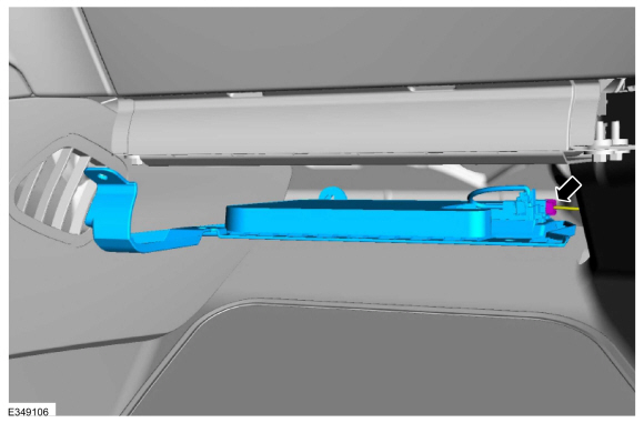
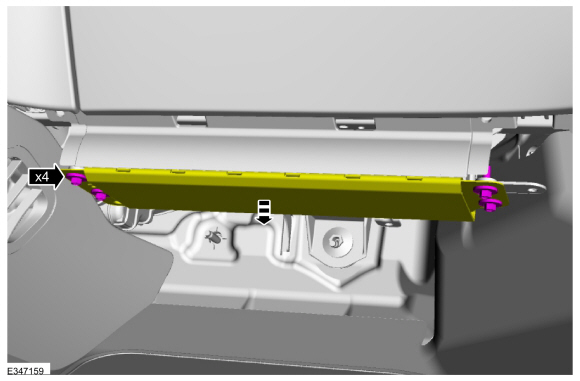
Remove the bolts and position the passenger knee airbag out from the instrument panel.
Torque: 71 lb.in (8 Nm)
 |
-
Remove the passenger knee airbag.
-
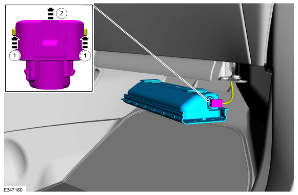
Raise the locking tabs of the passenger knee airbag electrical connector.
-
Disconnect the passenger knee airbag electrical connector.
-
Raise the locking tabs of the passenger knee airbag electrical connector.
 |
Installation
WARNING:
Incorrect repair techniques or actions can cause an
accidental Supplemental Restraint System deployment. Make sure the
restraint system is depowered before reconnecting the component. Refer
to the Supplemental Restraint System depowering General Procedure in
section 501-20B. Failure to precisely follow depowering instructions
could result in serious personal injury from an accidental deployment.
- To install, reverse the removal procedure.
-
Repower the SRS .
Refer to: Supplemental Restraint System (SRS) Repowering (501-20B Supplemental Restraint System, General Procedures).
 Passenger Airbag Deactivation (PAD) Indicator. Removal and Installation
Special Tool(s) /
General Equipment
Interior Trim Remover
Removal
NOTE:
Interior rear view mirror removed for clarity.
Remove the IPMA cover...
 Restraints Control Module (RCM). Removal and Installation
Removal
WARNING:
The following procedure prescribes critical repair steps
required for correct restraint system operation during a crash. Follow
all notes and steps carefully...
Other information:
Lincoln Nautilus 2018-2026 Owners Manual: Hill Start Assist
What Is Hill Start Assist Hill Start Assist makes it easier for you to pull away when your vehicle is on a slope without using the parking brake. How Does Hill Start Assist Work When the system activates, your vehicle remains stationary for a few seconds after you release the brake pedal...
Lincoln Nautilus 2018-2026 Service Manual: Steering Column - System Operation and Component Description. Description and Operation
System Diagram Item Description 1 DDM 2 SCCM 3 Memory Set Switch 4 DSM 5 BCM 6 MS-CAN 7 HS2-CAN 8 Steering Column Control Switch 9 Steering Column Tilt Motor 10 Hall Effect Sensor 11 GWM 12 Steering Column Telescopic Motor 13 Hall Effect Sensor 14 HS1-CAN System Operation Network Message..
Categories
- Manuals Home
- 1st Generation Nautilus Owners Manual
- 1st Generation Nautilus Service Manual
- Drive Mode Control
- Power Outlet - Vehicles With: 110V Power Outlet
- Engine Oil Capacity and Specification - 2.0L
- New on site
- Most important about car
Opening and Closing the Hood
Opening the Hood