Lincoln Nautilus: Supplemental Restraint System / Restraints Control Module (RCM). Removal and Installation
Removal
.jpg) WARNING:
The following procedure prescribes critical repair steps
required for correct restraint system operation during a crash. Follow
all notes and steps carefully. Failure to follow step instructions may
result in incorrect operation of the restraint system and increases the
risk of serious personal injury or death in a crash.
WARNING:
The following procedure prescribes critical repair steps
required for correct restraint system operation during a crash. Follow
all notes and steps carefully. Failure to follow step instructions may
result in incorrect operation of the restraint system and increases the
risk of serious personal injury or death in a crash.
NOTE: Removal steps in this procedure may contain installation details.
-
Refer to: Pyrotechnic Device Health and Safety Precautions (100-00 General Information, Description and Operation).
WARNING:
Before beginning any service procedure in this
manual, refer to health and safety warnings in section 100-00 General
Information. Failure to follow this instruction may result in serious
personal injury.
-
NOTE: This step is only necessary when installing a new component.
NOTE: The PMI process must begin with the current RCM installed. If the current RCM does not respond to the diagnostic scan tool, the tool may prompt for As-Built Data as part of the repair.
Using a diagnostic scan tool, begin the PMI process for the RCM following the on-screen instructions.
-
Depower the SRS .
Refer to: Supplemental Restraint System (SRS) Depowering (501-20 Supplemental Restraint System) .
-
Remove the floor console.
Refer to: Floor Console (501-12 Instrument Panel and Console) .
-
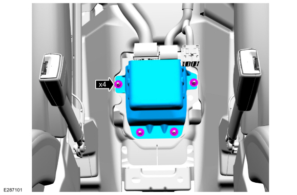
Remove the nuts and the RCM cover.
Torque: 80 lb.in (9 Nm)
 |
-
-
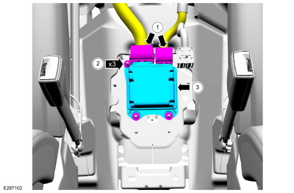
Disconnect the RCM electrical connectors.
-
Remove the nuts.
Torque: 106 lb.in (12 Nm)
-
Remove the RCM .
-
Disconnect the RCM electrical connectors.
 |
Installation
WARNING:
Incorrect repair techniques or actions can cause an
accidental Supplemental Restraint System deployment. Make sure the
restraint system is depowered before reconnecting the component. Refer
to the Supplemental Restraint System depowering General Procedure in
section 501-20B. Failure to precisely follow depowering instructions
could result in serious personal injury from an accidental deployment.
-
To install, reverse the removal procedure.
-
Repower the SRS . For a new RCM , do not prove out the SRS at this time.
Refer to: Supplemental Restraint System (SRS) Repowering (501-20 Supplemental Restraint System) .
-
NOTE: This step is only necessary when installing a new component.
Using a diagnostic scan tool, complete the PMI process for the RCM following the on-screen instructions.
-
NOTE: This step is only necessary when installing a new component.
Using a diagnostic scan tool, carry out the ABS module initialization following the on-screen instruction.
-
If a new RCM was installed, prove out the SRS
as follows: Verify all airbags are installed and connected and the
ignition is OFF. Wait 10 seconds then turn the ignition ON and monitor
the airbag warning indicator. The airbag warning indicator illuminates
continuously for approximately 6 seconds and turns off. Continue to
monitor the airbag warning indicator for approximately 30 seconds, as
this is the time required for the RCM to complete testing of the SRS .
-
If a SRS
fault is present, the airbag warning indicator either fails to light,
remains lit continuously or flashes. The flashing may not occur until
approximately 30 seconds after the ignition has been turned from OFF to
ON. If this occurs, diagnose and repair any SRS faults before proceeding with other repairs.
-
If, after the ignition has been turned on for 30
seconds, the airbag warning indicator remains unlit with no chime or SRS
message displayed in the message center, no SRS fault is present.
-
If the airbag warning indicator is inoperative and a SRS
fault exists, a chime sounds in a pattern of 5 sets of 5 beeps or a
message displays in the message center. If this occurs, diagnose and
repair the airbag warning indicator and any SRS faults before proceeding with other repairs.
-
If a SRS
fault is present, the airbag warning indicator either fails to light,
remains lit continuously or flashes. The flashing may not occur until
approximately 30 seconds after the ignition has been turned from OFF to
ON. If this occurs, diagnose and repair any SRS faults before proceeding with other repairs.
 Passenger Knee Airbag. Removal and Installation
Removal
WARNING:
The following procedure prescribes critical repair steps
required for correct restraint system operation during a crash. Follow
all notes and steps carefully...
 Seat Position Sensor. Removal and Installation
Removal
NOTE:
RH seat shown, LH seat similar.
NOTE:
Removal steps in this procedure may contain installation details.
Position the seat all the way back and up...
Other information:
Lincoln Nautilus 2018-2026 Service Manual: Lower Arm. Removal and Installation
Special Tool(s) / General Equipment Vehicle/Axle Stands Removal NOTICE: Suspension fasteners are critical parts that affect the performance of vital components and systems. Failure of these fasteners may result in major service expense...
Lincoln Nautilus 2018-2026 Service Manual: In-Vehicle Temperature and Humidity Sensor. Removal and Installation
Removal NOTE: Interior rear view mirror shown removed for clarity. Remove the IPMA cover. Release the IPMA cover clips. Disconnect the electrical connector(s). Disconnect the electrical connector...
Categories
- Manuals Home
- 1st Generation Nautilus Owners Manual
- 1st Generation Nautilus Service Manual
- Power Outlet - Vehicles With: 110V Power Outlet
- Fuel Quality
- Folding the Exterior Mirrors - Vehicles With: Manual Folding Mirrors. Folding the Exterior Mirrors - Vehicles With: Power Folding Mirrors
- New on site
- Most important about car
USB Ports
Locating the USB Ports
Data Transfer USB Ports

The USB Ports could be in the following locations:
On the lower instrument panel. Inside the media bin. Inside the center console.Note: These USB ports can also charge devices.