Lincoln Nautilus: Driveshaft / Rear Driveshaft - 2.7L EcoBoost (238kW/324PS). Removal and Installation
Special Tool(s) / General Equipment
| Flat Headed Screw Driver |
Removal
NOTE: Removal steps in this procedure may contain installation details.
-
Remove the muffler and tailpipe.
Refer to: Muffler and Tailpipe (309-00B Exhaust System - 2.7L EcoBoost (238kW/324PS), Removal and Installation).
-
Remove the exhaust flexible pipe.
Refer to: Exhaust Flexible Pipe (309-00B Exhaust System - 2.7L EcoBoost (238kW/324PS), Removal and Installation).
-
Remove the retainers and the underbody side shield.
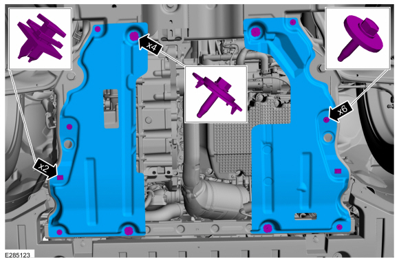 |
-
On both side.
Remove the retainers and separate the fender splash shield.
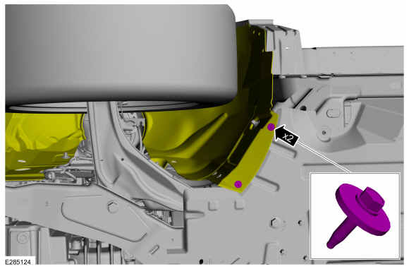 |
-
Remove the front air deflectors.
-
Remove the bolts.
-
Remove the bolts and position the front deflector noise shield aside.
-
Remove the stamped nuts and the front air deflectors.
-
Remove the bolts.
 |
-
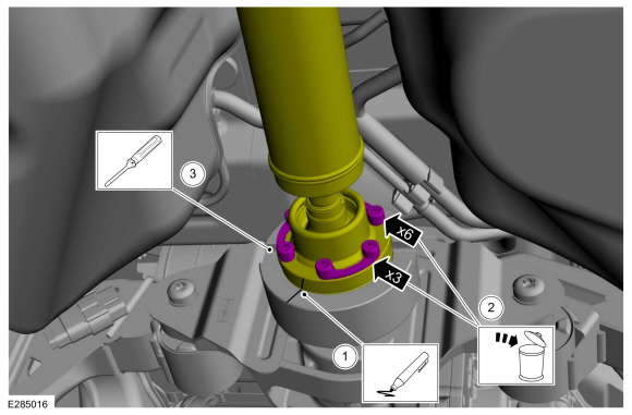
NOTE: The installation step requires the aid of another technician.
Remove and discard the driveshaft to PTU bolt and washer assemblies.
Torque: 26 lb.ft (35 Nm)
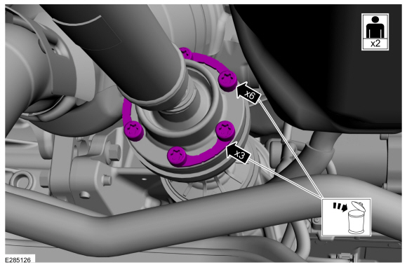 |
-
Separate the driveshaft from the PTU flange.
-
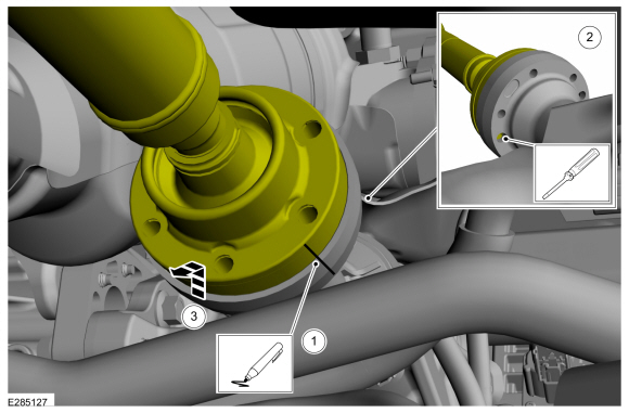
NOTE: Make sure that the component aligns with the installation mark.
Index-mark the driveshaft and PTU flange.
-
NOTICE: Do not remove driveshaft from the PTU flange by pulling on the driveshaft tube. Damage to the CV-joint can result.
Using general equipment, separate the driveshaft from the PTU flange.
Use the General Equipment: Flat Headed Screw Driver
-
Remove the driveshaft from the PTU flange.
-
 |
-
Separate the driveshaft from the drive pinion flange.
-
NOTE: Make sure that the component aligns with the installation mark.
Index-mark the driveshaft and RDU flange.
-
Remove and discard the driveshaft to drive pinion flange bolts and the retaining straps.
Torque: 26 lb.ft (35 Nm)
-
NOTICE: Do not remove driveshaft from the pinion flange by pulling on the driveshaft tube. Damage to the CV (constant velocity)-joint can result.
Using a general equipment, separate the driveshaft from the drive pinion flange.
Use the General Equipment: Flat Headed Screw Driver
-
 |
-
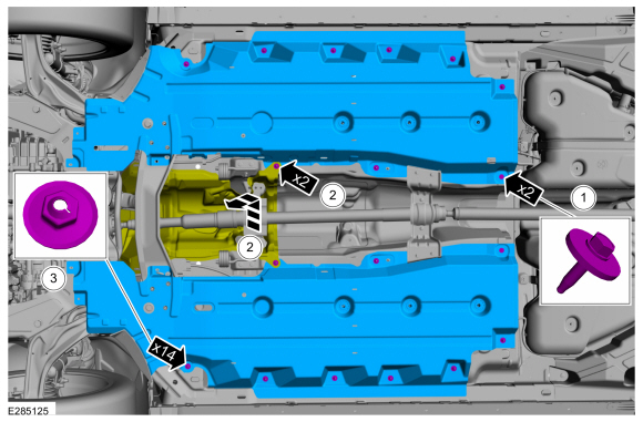
-
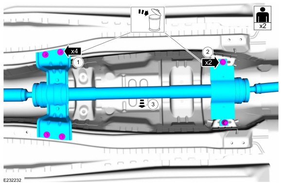
Remove and discard the rear center bearing tunnel brace bolts.
Torque: 22 lb.ft (30 Nm)
-
Remove and discard the front center bearing bracket bolts.
Torque: 41 lb.ft (55 Nm)
-
NOTICE: The driveshaft is long and heavy with multiple CV-joints. The help of a assistant will be needed. Do not over articulate the driveshaft or damage may occur.
NOTE: When installing the driveshaft, it will be necessary to hand start the front center bearing bolts before installing the rear center bearing tunnel brace bolts.
NOTE: When installing the driveshaft, it will be necessary to place the CV-joint flanges of the driveshaft into the PTU and RDU flanges before installing the center bearing bolts.
With the help from an assistant, remove the driveshaft.
-
Remove and discard the rear center bearing tunnel brace bolts.
 |
-
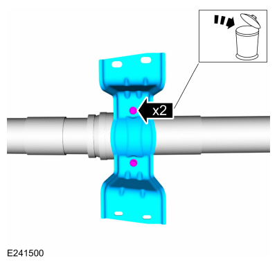
NOTE: This step is only necessary if the rear center bearing tunnel brace is being serviced.
NOTE: The rear center bearing tunnel brace can be replaced without removing the driveshaft.
-
Remove and discard the rear center bearing tunnel brace bolts.
Torque: 177 lb.in (20 Nm)
-
Remove the rear center bearing tunnel brace.
-
Remove and discard the rear center bearing tunnel brace bolts.
 |
Installation
-
NOTE: If a driveshaft is installed and driveshaft vibration is encountered after installation, index the driveshaft.
To install, reverse the removal procedure.
 Rear Driveshaft - 2.0L EcoBoost (184kW/250PS) – MI4. Removal and Installation
Special Tool(s) /
General Equipment
Flat Headed Screw Driver
Punch
Copper Hammer
Removal
NOTE:
Removal steps may contain installation instructions...

Other information:
Lincoln Nautilus 2018-2026 Service Manual: Heated Steering Wheel Module (HSWM). Removal and Installation
Removal NOTE: Removal steps in this procedure may contain installation details. NOTE: This step is only necessary when installing a new component. NOTE: The PMI process must begin with the current HSWM installed. If the current HSWM does not respond to the diagnostic scan tool, the tool may prompt for As-Built Data as part of the repair. Using a diagnostic scan tool, begin..
Lincoln Nautilus 2018-2026 Service Manual: Seatbelt Twisted at the Seatbelt Guide. General Procedures
Adjustment NOTE: Typical D-ring shown, others similar. If required, remove the necessary trim panel(s). Fold the seatbelt as indicated. Feed the folded portion of the seatbelt into the D-ring. Pull the seatbelt through the D-ring to remove the twist in the seatbelt. ..
Categories
- Manuals Home
- 1st Generation Nautilus Owners Manual
- 1st Generation Nautilus Service Manual
- Drive Mode Control
- Anti-Theft Alarm System Settings. Security – Troubleshooting
- USB Ports
- New on site
- Most important about car
Locating the Pre-Collision Assist Sensors

If a message regarding a blocked sensor or camera appears in the information display, something is obstructing the radar signals or camera images. The radar sensor is behind the fascia cover in the center of the lower grille. With a blocked sensor or camera, the system may not function, or performance may reduce. See Pre-Collision Assist – Information Messages.