Lincoln Nautilus: Rear End Sheet Metal Repairs / Rear Floor Panel. Removal and Installation
Special Tool(s) /
General Equipment
| Scraper for Straight Edges |
| Grinder |
| Hot Air Gun |
| 8 mm Drill Bit |
| MIG/MAG Welding Equipment |
| Spot Weld Drill Bit |
| Locking Pliers |
Materials
| Name |
Specification |
Seam Sealer
TA-2-B, 3M™ 08308, LORD Fusor® 803DTM |
-
|
Removal
NOTE:
Roof removed for clarity.
NOTE:
Factory welds may be substituted with resistance or metal
inert gas (MIG) plug welds. Resistance welds may not be placed directly
over original location. They must be placed adjacent to original
location and match factory welds in quantity. Metal inert gas (MIG) plug
welds must equal factory welds in both location and quantity.
NOTE:
Adequately protect all adjacent areas against cutting, grinding and welding procedures.
-
Depower the SRS .
Refer to: Supplemental Restraint System (SRS) Depowering (501-20B Supplemental Restraint System, General Procedures).
-
Restore vehicle to pre-accident dimensions, if required.
Refer to: Body and Frame (501-26 Body Repairs - Vehicle Specific Information and Tolerance Checks, Description and Operation).
-
Position the carpeting and the wiring harness away from the working area.
-
Remove the following items:
-
Remove the rear bumper.
Refer to: Rear Bumper (501-19 Bumpers, Removal and Installation).
-
Remove the rear subframe (as equipped).
Refer to: Rear Subframe - AWD (502-00 Uni-Body, Subframe and Mounting System, Removal and Installation).
Refer to: Rear Subframe - FWD (502-00 Uni-Body, Subframe and Mounting System, Removal and Installation).
-
Remove the fuel tank (as equipped).
Refer to: Fuel Tank (310-01A Fuel Tank and Lines - 2.0L EcoBoost (184kW/250PS) – MI4, Removal and Installation).
Refer to: Fuel Tank (310-01B Fuel Tank and Lines - 2.7L EcoBoost (238kW/324PS), Removal and Installation).
-
Remove the rear seat backrest.
Refer to: Rear Seat Backrest (501-10B Rear Seats, Removal and Installation).
-
Remove the loadspace trim panel.
Refer to: Loadspace Trim Panel (501-05 Interior Trim and Ornamentation, Removal and Installation).
-
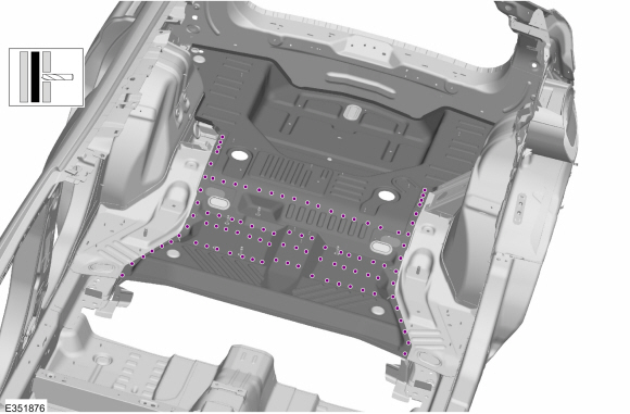
Using a grinder with an abrasive disc or equivalent, remove the sealer along the floor panel rear flange.
Use the General Equipment: Grinder
-
Using a grinder with an abrasive disc or equivalent, remove the sealer along the floor panel flange on the LH side.
Use the General Equipment: Grinder
-
Using a grinder with an abrasive disc or equivalent, remove the sealer along the floor panel flange on the RH side.
Use the General Equipment: Grinder
-
Using a grinder with an abrasive disc or equivalent, remove the sealer along the floor panel front flange.
Use the General Equipment: Grinder
-
NOTICE:
Use a heat gun to warm the mastic material, using caution not overheat, as the material is flammable.
Remove the mastic material from the floor panel.
Use the General Equipment: Hot Air Gun
Use the General Equipment: Scraper for Straight Edges
-
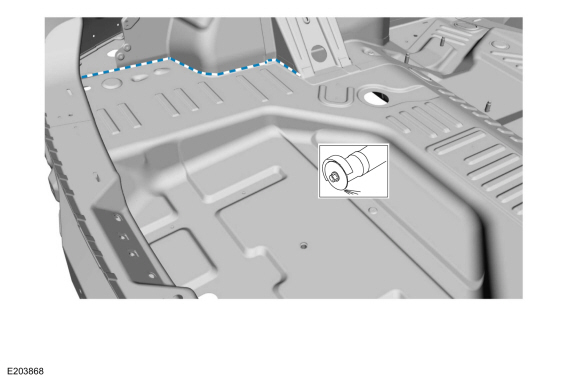
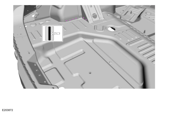
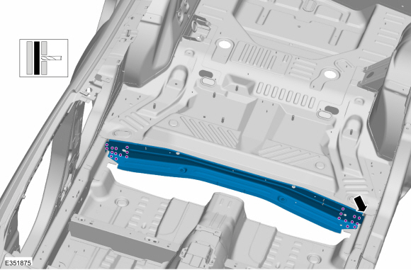
Remove the spot welds along the floor panel rear flange.
Use the General Equipment: Spot Weld Drill Bit
-
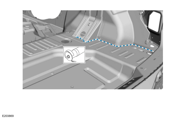
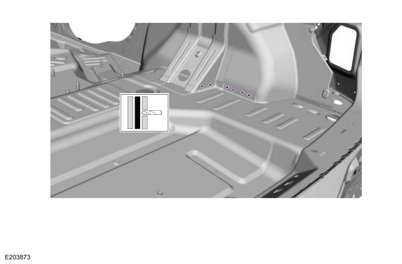
Remove the spot welds along the floor panel wheelhouse flange, on the LH side.
Use the General Equipment: Spot Weld Drill Bit
-
Remove the spot welds along the floor panel wheelhouse flange, on the RH side.
Use the General Equipment: Spot Weld Drill Bit
-
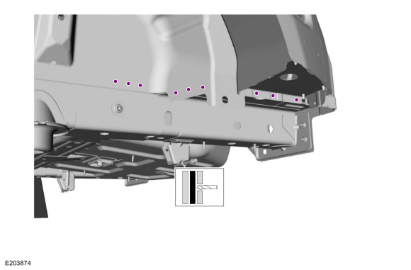
Remove the spot welds along the floor panel lower wheelhouse flange, on both sides.
Use the General Equipment: Spot Weld Drill Bit
-
NOTE:
Back panel removed from view for clarity.
Remove the floor panel spot welds.
Use the General Equipment: Spot Weld Drill Bit
-
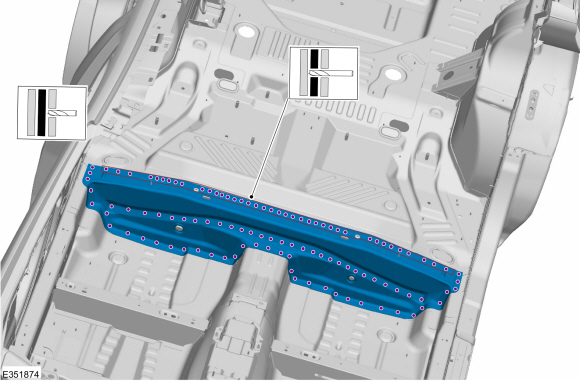
Remove the welds and the crossmember.
Use the General Equipment: Spot Weld Drill Bit
-
Remove the welds and the crossmember.
Use the General Equipment: Spot Weld Drill Bit
-
Remove the floor panel spot welds.
Use the General Equipment: Spot Weld Drill Bit
-
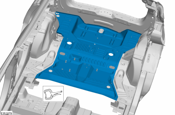
Remove the rear floor panel.
Installation
NOTE:
Roof removed for clarity.
NOTE:
Factory welds may be substituted with resistance or metal
inert gas (MIG) plug welds. Resistance welds may not be placed directly
over original location. They must be placed adjacent to original
location and match factory welds in quantity. Metal inert gas (MIG) plug
welds must equal factory welds in both location and quantity.
NOTE:
Adequately protect all adjacent areas against cutting, grinding and welding procedures.
-
Drill plug weld holes in the replacement rear floor panel.
Use the General Equipment: 8 mm Drill Bit
-
Install, properly position and clamp the rear floor panel.
Use the General Equipment: Locking Pliers
-
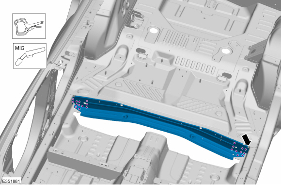
Install the welds.
Use the General Equipment: MIG/MAG Welding Equipment
-
Install the welds and the crossmember.
Use the General Equipment: Locking Pliers
Use the General Equipment: MIG/MAG Welding Equipment
-
Install the welds and the crossmember.
Use the General Equipment: Locking Pliers
Use the General Equipment: MIG/MAG Welding Equipment
-
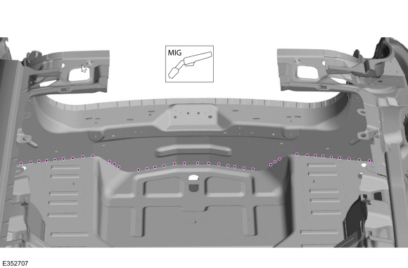
Weld the floor panel rear flange.
Use the General Equipment: MIG/MAG Welding Equipment
-
Weld the floor panel to side members and crossmember.
Use the General Equipment: MIG/MAG Welding Equipment
-
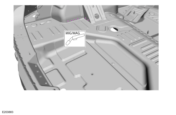
Weld the floor panel at the LH wheelhouse.
Use the General Equipment: MIG/MAG Welding Equipment
-
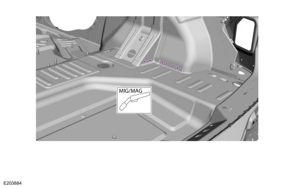
Weld the floor panel at the RH wheelhouse.
Use the General Equipment: MIG/MAG Welding Equipment
-
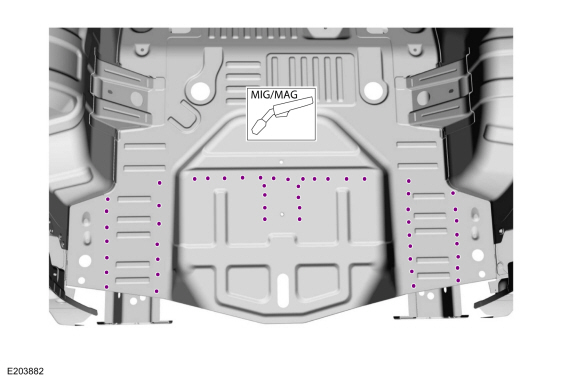
Weld the lower floor panel flange on both sides.
Use the General Equipment: MIG/MAG Welding Equipment
-
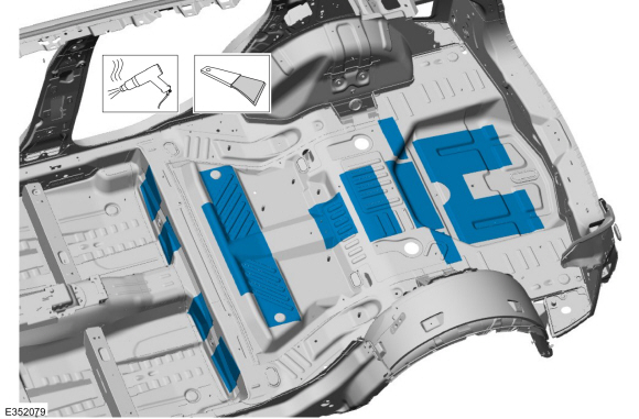
Finish the repair area using typical metal finishing techniques.
-
Refinish using a Ford approved paint system.
-
Restore corrosion protection.
Refer to: Corrosion Prevention (501-25 Body Repairs - General Information, General Procedures).
-
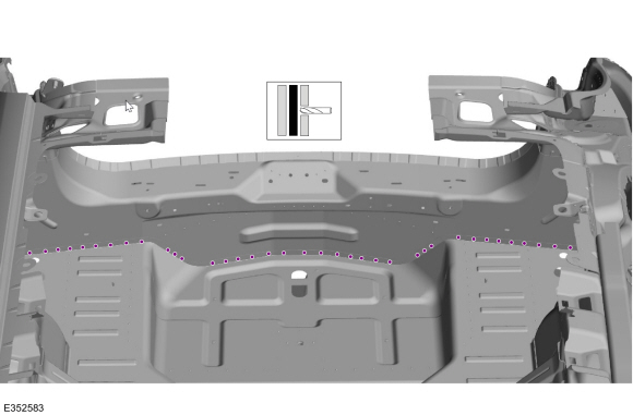
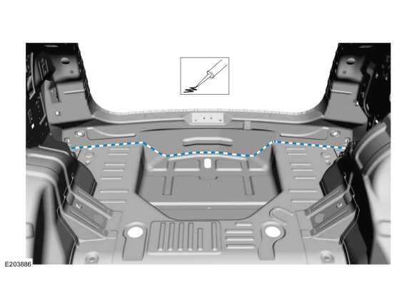
Apply sealer to the floor panel rear flange.
Material: Seam Sealer
/ TA-2-B, 3M™ 08308, LORD Fusor® 803DTM
-
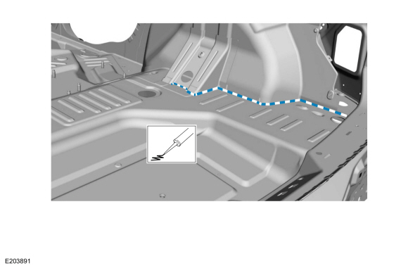
Apply sealer to the floor panel rear flange on the LH side.
Material: Seam Sealer
/ TA-2-B, 3M™ 08308, LORD Fusor® 803DTM
-
Apply sealer to the floor panel rear flange on the RH side.
Material: Seam Sealer
/ TA-2-B, 3M™ 08308, LORD Fusor® 803DTM
-
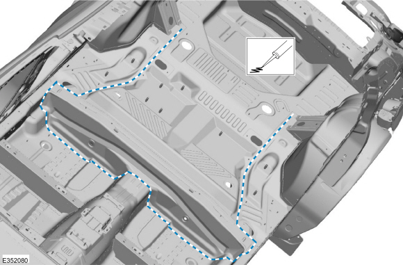
Apply sealer to the floor panel front flange.
Material: Seam Sealer
/ TA-2-B, 3M™ 08308, LORD Fusor® 803DTM
-
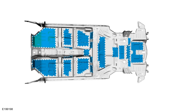
Apply NVH material (obtain locally) in original locations.
-
Sealing work: All areas must be sealed to production level.
-
Reposition the carpeting and the wiring harness.
-
Install the following items:
-
Install the rear bumper.
Refer to: Rear Bumper (501-19 Bumpers, Removal and Installation).
-
Install the rear subframe (as equipped).
Refer to: Rear Subframe - AWD (502-00 Uni-Body, Subframe and Mounting System, Removal and Installation).
Refer to: Rear Subframe - FWD (502-00 Uni-Body, Subframe and Mounting System, Removal and Installation).
-
Install the fuel tank (as equipped).
Refer to: Fuel Tank (310-01A Fuel Tank and Lines - 2.0L EcoBoost (184kW/250PS) – MI4, Removal and Installation).
Refer to: Fuel Tank (310-01B Fuel Tank and Lines - 2.7L EcoBoost (238kW/324PS), Removal and Installation).
-
Install the rear seat backrest.
Refer to: Rear Seat Backrest (501-10B Rear Seats, Removal and Installation).
-
Install the loadspace trim panel.
Refer to: Loadspace Trim Panel (501-05 Interior Trim and Ornamentation, Removal and Installation).
-
Repower the SRS .
Refer to: Supplemental Restraint System (SRS) Repowering (501-20B Supplemental Restraint System, General Procedures).
Special Tool(s) /
General Equipment
8 mm Drill Bit
MIG/MAG Welding Equipment
Spot Weld Drill Bit
Locking Pliers
Removal
NOTE:
LH side shown, RH side similar...
Special Tool(s) /
General Equipment
8 mm Drill Bit
MIG/MAG Welding Equipment
Spot Weld Drill Bit
Locking Pliers
Materials
Name
Specification
Seam SealerTA-2-B, 3M™ 08308, LORD Fusor® 803DTM
-
Removal
NOTE:
Factory welds may be substituted with resistance or metal
inert gas (MIG) plug welds...
Other information:
Removal
NOTE:
Removal steps in this procedure may contain installation details.
All vehicles
Remove the rear bumper cover.
Refer to: Rear Bumper Cover (501-19)
.
Vehicles without trailer tow
Remove the rear bumper...
Selecting the Correct Fuel
Your vehicle operates on regular unleaded
gasoline with a minimum pump (R+M)/2
octane rating of 87.
Some fuel stations, particularly those in high
altitude areas, offer fuels posted as regular
unleaded gasoline with an octane rating
below 87...
Categories
How Does Traction Control Work
If your vehicle begins to slide, the system
applies the brakes to individual wheels and,
when needed, reduces power at the same
time. If the wheels spin when accelerating
on slippery or loose surfaces, the system
reduces power in order to increase traction.
Switching Traction Control On and Off
WARNING: The stability and traction
control light illuminates steadily if the
system detects a failure. Make sure you
did not manually disable the traction
control system using the information
display controls or the switch. If the stability
control and traction control light is still
illuminating steadily, have the system
serviced by an authorized dealer
immediately. Operating your vehicle with
the traction co
read more
.jpg)

.jpg)
.jpg)
.jpg)

.jpg)
.jpg)
.jpg)
 Rear Exhaust Mounting Bracket. Removal and Installation
 Rear Floor Panel Crossmember. Removal and Installation