Lincoln Nautilus: Rear End Sheet Metal Repairs / Rear Floor Panel Crossmember. Removal and Installation
Special Tool(s) / General Equipment
| 8 mm Drill Bit | |
| MIG/MAG Welding Equipment | |
| Spot Weld Drill Bit | |
| Locking Pliers |
Materials
| Name | Specification |
|---|---|
| Seam Sealer TA-2-B, 3M™ 08308, LORD Fusor® 803DTM |
- |
Removal
NOTE: Factory welds may be substituted with resistance or metal inert gas (MIG) plug welds. Resistance welds may not be placed directly over original location. They must be placed adjacent to original location and match factory welds in quantity. Metal inert gas (MIG) plug welds must equal factory welds in both location and quantity.
NOTE: Adequately protect all adjacent areas against cutting, grinding and welding procedures.
-
Depower the SRS .
Refer to: Supplemental Restraint System (SRS) Depowering (501-20B Supplemental Restraint System, General Procedures).
-
If Required:
Dimensionally restore the vehicle to pre-damage condition.
Refer to: Body and Frame (501-26 Body Repairs - Vehicle Specific Information and Tolerance Checks, Description and Operation).
-
If Required:
Remove the rear subframe or the beam axle.
Refer to: Rear Subframe - AWD (502-00 Uni-Body, Subframe and Mounting System, Removal and Installation).
Refer to: Rear Subframe - FWD (502-00 Uni-Body, Subframe and Mounting System, Removal and Installation).
-
Remove the fuel tank.
Refer to: Fuel Tank (310-01A Fuel Tank and Lines - 2.0L EcoBoost (184kW/250PS) – MI4, Removal and Installation).
Refer to: Fuel Tank (310-01B Fuel Tank and Lines - 2.7L EcoBoost (238kW/324PS), Removal and Installation).
-
Position all fuel and brake lines away from the working area.
-
On Both Sides:
Remove the welds.
Use the General Equipment: Spot Weld Drill Bit
.jpg) |
-
Remove the rear seat backrest.
Refer to: Rear Seat Backrest (501-10B Rear Seats, Removal and Installation).
-
NOTE: Pay particular attention to the location of adhesives and sealers to aid in installation.
Remove the welds and the rear floor panel crossmember.
Use the General Equipment: Spot Weld Drill Bit
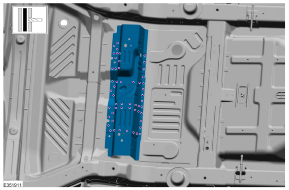 |
Installation
NOTE: Factory welds may be substituted with resistance or metal inert gas (MIG) plug welds. Resistance welds may not be placed directly over original location. They must be placed adjacent to original location and match factory welds in quantity. Metal inert gas (MIG) plug welds must equal factory welds in both location and quantity.
NOTE: Adequately protect all adjacent areas against cutting, grinding and welding procedures.
-
Drill plug weld holes in the replacement rear floor panel crossmember.
Use the General Equipment: 8 mm Drill Bit
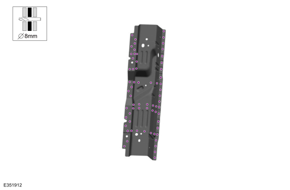 |
-
Install, properly position, clamp and weld the replacement rear floor panel crossmember.
Use the General Equipment: Locking Pliers
Use the General Equipment: MIG/MAG Welding Equipment
.jpg) |
-
On Both Sides:
Drill plug weld holes in the replacement rear floor side member.
Use the General Equipment: 8 mm Drill Bit
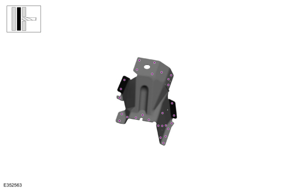 |
-
On Both Sides:
Install, properly position, clamp and weld the replacement rear floor side member.
Use the General Equipment: Locking Pliers
Use the General Equipment: MIG/MAG Welding Equipment
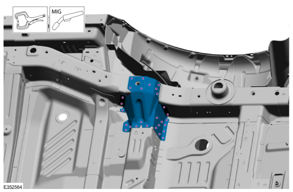 |
-
Dress all welds as required using typical metal finishing techniques.
-
Seam Sealing:
All seams must be sealed to production level.
Material: Seam Sealer / TA-2-B, 3M™ 08308, LORD Fusor® 803DTM
.jpg) |
-
Install the rear seat backrest.
Refer to: Rear Seat Backrest (501-10B Rear Seats, Removal and Installation).
-
Refinish the entire repair using a Ford approved paint system.
-
Restore corrosion protection.
Refer to: Corrosion Prevention (501-25 Body Repairs - General Information, General Procedures).
-
Install the fuel tank.
Refer to: Fuel Tank (310-01A Fuel Tank and Lines - 2.0L EcoBoost (184kW/250PS) – MI4, Removal and Installation).
Refer to: Fuel Tank (310-01B Fuel Tank and Lines - 2.7L EcoBoost (238kW/324PS), Removal and Installation).
-
Reposition all fuel and brake lines to original locations.
-
If Required:
Install the rear subframe or the beam axle.
Refer to: Rear Subframe - AWD (502-00 Uni-Body, Subframe and Mounting System, Removal and Installation).
Refer to: Rear Subframe - FWD (502-00 Uni-Body, Subframe and Mounting System, Removal and Installation).
-
Repower the SRS .
Refer to: Supplemental Restraint System (SRS) Repowering (501-20B Supplemental Restraint System, General Procedures).
 Rear Floor Panel. Removal and Installation
Special Tool(s) /
General Equipment
Scraper for Straight Edges
Grinder
Hot Air Gun
8 mm Drill Bit
MIG/MAG Welding Equipment
Spot Weld Drill Bit
Locking Pliers
Materials
Name
Specification
Seam SealerTA-2-B, 3M™ 08308, LORD Fusor® 803DTM
-
Removal
NOTE:
Roof removed for clarity...
 Rear Floor Panel Reinforcement. Removal and Installation
Special Tool(s) /
General Equipment
8 mm Drill Bit
MIG/MAG Welding Equipment
Spot Weld Drill Bit
Locking Pliers
Materials
Name
Specification
Seam SealerTA-2-B, 3M™ 08308, LORD Fusor® 803DTM
-
Removal
NOTE:
Factory welds may be substituted with resistance or metal
inert gas (MIG) plug welds...
Other information:
Lincoln Nautilus 2018-2026 Service Manual: Rear Seat Backrest. Removal and Installation
Removal WARNING: The following procedure describes critical repair steps required for correct seat component installation. Follow all notes and steps carefully. Do not place any objects between the seat components and the body of the vehicle, nor any objects within a joint internal to the seat structure...
Lincoln Nautilus 2018-2026 Service Manual: Rear Camber Adjustment. General Procedures
Special Tool(s) / General Equipment Wheel Alignment System Adjustment NOTICE: Suspension fasteners are critical parts that affect the performance of vital components and systems. Failure of these fasteners may result in major service expense...
Categories
- Manuals Home
- 1st Generation Nautilus Owners Manual
- 1st Generation Nautilus Service Manual
- Folding the Exterior Mirrors - Vehicles With: Manual Folding Mirrors. Folding the Exterior Mirrors - Vehicles With: Power Folding Mirrors
- Drive Mode Control
- Interior Lamp Function. Adjusting the Instrument Panel Lighting Brightness. Ambient Lighting. Interior Lighting – Troubleshooting
- New on site
- Most important about car
Locating the Pre-Collision Assist Sensors

If a message regarding a blocked sensor or camera appears in the information display, something is obstructing the radar signals or camera images. The radar sensor is behind the fascia cover in the center of the lower grille. With a blocked sensor or camera, the system may not function, or performance may reduce. See Pre-Collision Assist – Information Messages.