Lincoln Nautilus: Rear Drive Halfshafts / Rear Halfshaft. Removal and Installation
Special Tool(s) / General Equipment
 |
100-001
(T50T-100-A)
Slide Hammer |
 |
205-243 Remover, Halfshaft TKIT-1986-LM TKIT-1986-F |
 |
205-832 Remover, Halfshaft TKIT-2006C-FFMFLM TKIT-2006C-LM TKIT-2006C-ROW |
Removal
NOTICE: Never pick up or hold the halfshaft by only the inner or outer Constant Velocity (CV) joint. Damage to the CV joint will occur.
NOTICE: Never use a hammer to remove or install the halfshafts. Damage to the CV joint may occur.
NOTICE: Never use the halfshaft assembly as a lever to position other components. Damage to the halfshaft or CV joint may occur.
NOTICE: Do not allow the boots to contact sharp edges or hot exhaust components. Damage to the halfshaft boots will occur.
NOTICE: Do not drop assembled halfshafts. The impact may cut the boots from the inside without evidence of external damage.
-
Remove the wheel knuckle.
Refer to: Wheel Knuckle - AWD (204-02 Rear Suspension, Removal and Installation).
-
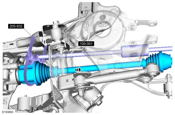
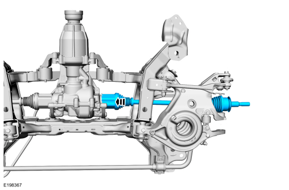
NOTE: Slide hammer extension may be needed.
Using the special tools, remove the rear halfshaft.
Use Special Service Tool: 205-832 Remover, Halfshaft. , 100-001 (T50T-100-A) Slide Hammer. , 205-243 Remover, Halfshaft.
 |
-
-
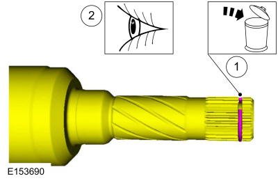
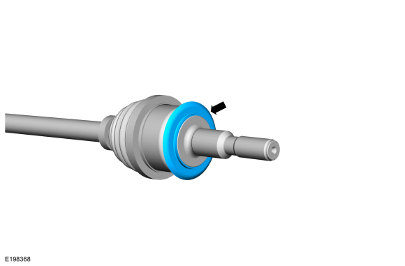
Remove and discard the halfshaft retaining circlip.
-
Inspect the halfshaft end for damage.
-
Remove and discard the halfshaft retaining circlip.
 |
Installation
-
NOTE: The halfshaft seal has to be replaced whenever the halfshaft is removed.
Replace the rear halfshaft seal.
Refer to: Rear Halfshaft Seal (205-02 Rear Drive Axle/Differential, Removal and Installation).
-
NOTICE: End output state control within 5 minutes of activation. Failure to end output state control within 5 minutes may cause damage to the RDU clutch motor.
LH side only.
-
Using the scan tool, actuate the following AWD
PID : RDU_TRQ_REQ# to approximately 500 Nm.
-
Using the scan tool, actuate the following AWD
PID : RDU_TRQ_REQ# to approximately 500 Nm.
-
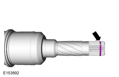
Install the new rear halfshaft retaining circlip.
 |
-
If equipped, replace the rear halfshaft slinger if damaged.
 |
-
NOTE: When seated correctly, the halfshaft retainer circlip can be felt as it snaps into the differential side gear groove.
NOTE: After insertion, pull the halfshaft inner end to make sure the circlip is locked.
Install the rear halfshaft.
 |
-
Check and top off the differential fluid.
Refer to: Differential Fluid Level Check (205-02 Rear Drive Axle/Differential, General Procedures).
-
Install the wheel knuckle.
Refer to: Wheel Knuckle - AWD (204-02 Rear Suspension, Removal and Installation).
 Rear Drive Halfshafts. Diagnosis and Testing
Preliminary Inspection
Visually inspect the CV joints, housing, boots, and clamps for obvious signs of mechanical damage.
If an obvious cause for an observed or reported concern is
found, correct the cause (if possible) before proceeding to the next
step
If the cause is not visually evident, verify the symptom and REFER to Symptom Chart: NVH...
 Brake System
..
Other information:
Lincoln Nautilus 2018-2026 Service Manual: Rear Seatbelt Retractor and Pretensioner. Removal and Installation
Removal WARNING: The following procedure prescribes critical repair steps required for correct restraint system operation during a crash. Follow all notes and steps carefully. Failure to follow step instructions may result in incorrect operation of the restraint system and increases the risk of serious personal injury or death in a crash. NOTE: Removal steps in this procedure ..
Lincoln Nautilus 2018-2026 Owners Manual: Headlamps
Using the High Beam Headlamps Push the lever away from you to switch the high beam on. Push the lever forward again or pull the lever toward you to switch the high beams off. Slightly pull the lever toward you and release it to flash the headlamps. Switching Headlamp Exit Delay On and Off To switch headlamp exit delay on, pull the turn signal lever toward you after switching your vehicle of..
Categories
- Manuals Home
- 1st Generation Nautilus Owners Manual
- 1st Generation Nautilus Service Manual
- Switching the Lane Keeping System On and Off. Switching the Lane Keeping System Mode
- Drive Mode Control
- Interior Lamp Function. Adjusting the Instrument Panel Lighting Brightness. Ambient Lighting. Interior Lighting – Troubleshooting
- New on site
- Most important about car
Replacing the Rear Wiper Blades
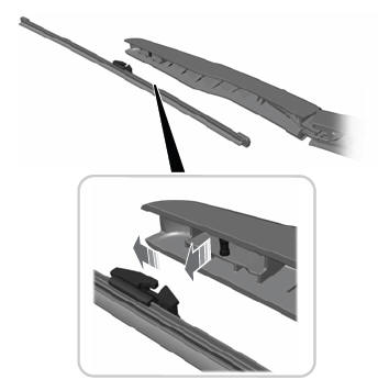
Note: Do not hold the wiper blade to lift the wiper arm.
Remove the wiper blade.