Lincoln Nautilus: Uni-Body, Subframe and Mounting System / Rear Subframe - AWD. Removal and Installation
Special Tool(s) /
General Equipment
.jpg) |
300-OTC1585AE
Powertrain Lift |
| Wooden Block |
Removal
NOTICE:
Suspension fasteners are critical parts that affect the
performance of vital components and systems. Failure of these fasteners
may result in major service expense. Use the same or equivalent parts if
replacement is necessary. Do not use a replacement part of lesser
quality or substitute design. Tighten fasteners as specified.
-
On both sides.
Remove the rear halfshaft.
Refer to: Rear Halfshaft (205-05 Rear Drive Halfshafts, Removal and Installation).
-
On both sides.
Remove the rear toe link.
Refer to: Toe Link (204-02 Rear Suspension, Removal and Installation).
-
On both sides.
Remove the rear lower arm.
Refer to: Lower Arm (204-02 Rear Suspension, Removal and Installation).
-
On both sides.
Remove the rear spring.
Refer to: Spring (204-02 Rear Suspension, Removal and Installation).
-
Remove the rear stabilizer bar.
Refer to: Rear Stabilizer Bar (204-02 Rear Suspension, Removal and Installation).
-
Remove the muffler and tailpipe.
Refer to: Muffler and Tailpipe (309-00A Exhaust System - 2.0L EcoBoost (184kW/250PS) – MI4, Removal and Installation).
Refer to: Muffler and Tailpipe (309-00B Exhaust System - 2.7L EcoBoost (238kW/324PS), Removal and Installation).
-
Remove the retainers and the rear air deflectors.
-
Separate the driveshaft from the drive pinion flange.
-
NOTE:
Make sure that the component aligns with the installation mark.
Index-mark the driveshaft flange and the RDU companion flange to maintain alignment during installation.
-
Remove and discard the driveshaft to drive pinion companion flange bolts and the retaining straps.
Torque:
26 lb.ft (35 Nm)
-
NOTICE:
Do not remove driveshaft from the pinion flange
by pulling on the driveshaft tube. Damage to the CV-joint can result.
Using a general equipment, separate the driveshaft from the drive pinion flange.
-
Position and support the driveshaft aside.
-
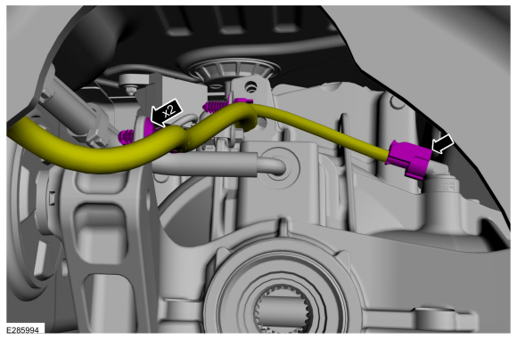
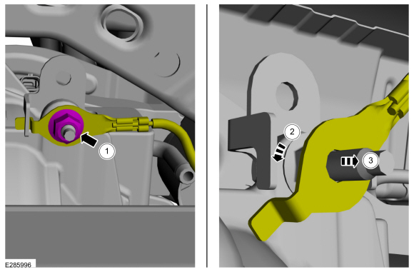
Disconnect the rear DCMR electrical connector and detach wiring harness retainer.
-
Disconnect rear RDU sensor connector and detach wiring harness retainers.
-
-
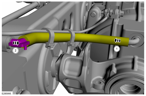
Remove the rear differential vent hose from RDU .
-
Detach the connector and position the vent hose aside.
-
-
Remove the ground cable nut.
-
Turn the ground cable.
-
Remove the ground cable.
-
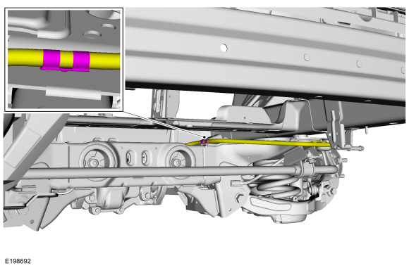
Detach the rear differential vent tube from the rear subframe.
-
Detach the rear differential vent tube from under the RH rear wheel arch liner.
-
On both sides.
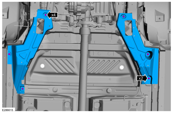
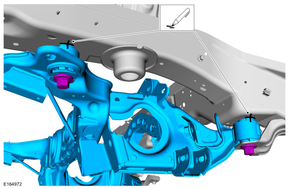
Index mark the subframe.
-
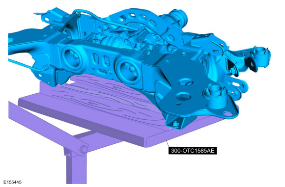
Position the powertrain lift and wooden blocks under the rear subframe.
Use Special Service Tool: 300-OTC1585AE
Powertrain Lift.
Use the General Equipment: Wooden Block
-
-
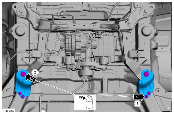
Remove and discard the subframe bracket bolts and remove the subframe brackets.
-
Remove and discard the rear subframe forward bolts.
-
Remove and discard the rear subframe rearward bolts.
Torque:
129 lb.ft (175 Nm)
-
Lower the rear subframe from the vehicle.
Use Special Service Tool: 300-OTC1585AE
Powertrain Lift.
Use the General Equipment: Wooden Block
Installation
-
Raise the rear subframe and position it to the vehicle.
Use Special Service Tool: 300-OTC1585AE
Powertrain Lift.
Use the General Equipment: Wooden Block
-
On both sides.
Align the reference marks made during removal.
-
-
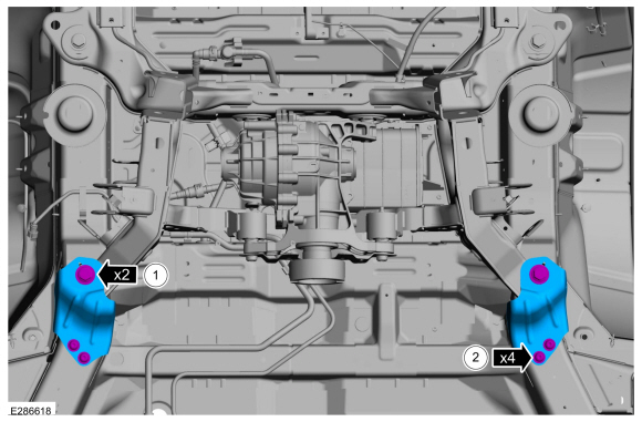
Position the rear subframe brackets and install the new rear subframe forward bolts.
Torque:
129 lb.ft (175 Nm)
-
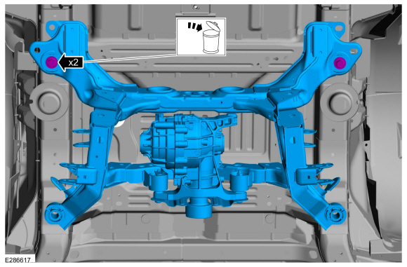
Install the new rear subframe bracket bolts.
Torque:
41 lb.ft (55 Nm)
-
To install, reverse the removal procedure.
Special Tool(s) /
General Equipment
014-3KLIFTTABLEPowertrain Lift Table
Tie Rod End Remover
Steering Wheel Holder
Wooden Block
Materials
Name
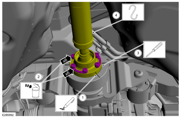
Specification
Motorcraft® Threadlock 262TA-26
WSK-M2G351-A6
Removal
NOTICE:
Suspension fasteners are critical parts that affect the
performance of vital components and systems...
Special Tool(s) /
General Equipment
300-OTC1585AEPowertrain Lift
Wooden Block
Removal
NOTICE:
Suspension fasteners are critical parts that affect the
performance of vital components and systems...
Other information:
System Operation
Headlamps
System Diagram
Item
Description
1
HS-CAN2
2
BCM
3
LH low beam
4
LH high beam
5
RH low beam
6
RH high beam
7
SCCM
8
LH steering column multifunction switch
9
IPMA
10
GWM
11
HS-CAN1
12
Start/Stop switch
13
HCM
14
LIN
..
Special Tool(s) /
General Equipment
Interior Trim Remover
Removal
NOTE:
Removal steps in this procedure may contain installation details.
Front Cable
Remove the hood latch.
Refer to: Hood Latch (501-14 Handles, Locks, Latches and Entry Systems, Removal and Installation).
Open the top cover.
Release the clips.
Open the top cover.
..
.jpg)
.jpg)


.jpg)
 Front Subframe. Removal and Installation
 Rear Subframe - FWD. Removal and Installation