Lincoln Nautilus: Power Steering / Tie Rod. Removal and Installation
Special Tool(s) / General Equipment
| Tie Rod Remover and Installer | |
| Boot Clamp Pliers |
Materials
| Name | Specification |
|---|---|
| Motorcraft® Premium Long-Life Grease XG-1-E1 |
ESA-M1C75-B |
Removal
NOTICE: When servicing inner tie rods, install a new bellows boot and clamps. The boots and clamps are designed to provide an airtight seal and protect the internal components of the steering gear. If the seal is not airtight, the vacuum generated during turning will draw water and contamination into the gear, causing failure of the steering gear components. Zip ties must not be used as they do not provide an airtight seal.
NOTICE: The inner ball joint grease is not compatible with water contamination. Do not allow water to become trapped in the grease or degradation and failure of the joint may occur.
NOTE: If the RH inner tie rod is being serviced, remove the LH outer tie rod end and bellows boot to access and hold the steering rack when loosening and tightening the inner tie rod.
-
NOTICE: Disconnect the battery ground cable anytime the steering linkage is being serviced or damage to the steering gear may occur resulting in steering gear replacement.
Disconnect the battery ground cable.
-
Remove the wheel and tire.
Refer to: Wheel and Tire (204-04A Wheels and Tires, Removal and Installation).
-
Remove the tie rod end.
Refer to: Tie Rod End (211-02 Power Steering, Removal and Installation).
-
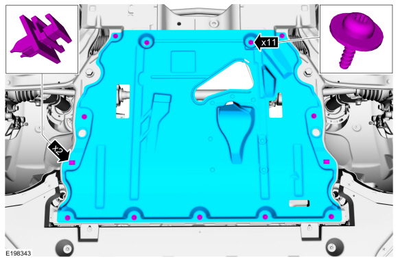
If equipped.
Remove the retainers and the under body shield.
 |
-
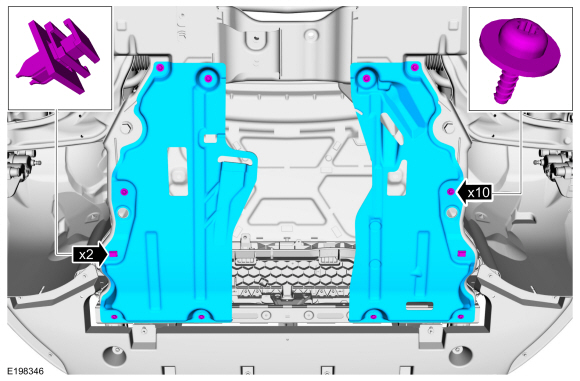
If equipped.
Remove the retainers and the dual under body shields.
 |
-
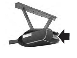
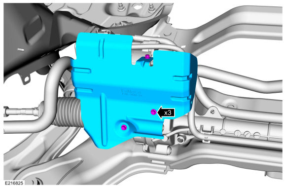
If equipped
Remove the retainers and the steering gear heat shield.
 |
-
Remove and discard the clamps and the steering gear bellows boot.
 |
-
NOTICE: Place the steering gear at the center position and hold the steering gear rack while loosening or tightening the inner tie rod. Use an appropriate-sized wrench on the flat/teeth of the rack to resist rotation and to prevent damage during removal of the inner tie rod.
NOTE: An assistant will be needed to hold the steering gear rack on the LH side when servicing the RH inner tie rod.
NOTE: Crowfoot-style inner tie-rod tool shown.
Remove the tie rod.
Use the General Equipment: Tie Rod Remover and Installer
 |
Installation
-
NOTICE: Place the steering gear at the center position and hold the steering gear rack while loosening or tightening the inner tie rod. Use an appropriate-sized wrench on the flat/teeth of the rack to resist rotation and to prevent damage during removal of the inner tie rod.
NOTE: An assistant will be needed to hold the steering gear rack on the LH side when servicing the RH inner tie rod.
NOTE: Crowfoot-style inner tie-rod tool shown.
Install the tie rod.
Use the General Equipment: Tie Rod Remover and Installer
Torque: 77 lb.ft (105 Nm)
|
-
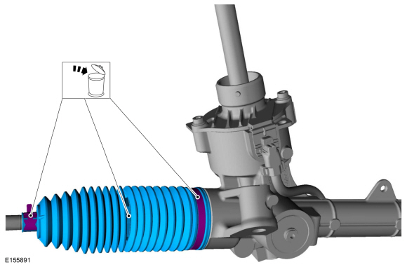
Apply the specified grease to the steering
gear-to-bellows boot mating surface and bellows boot groove on the inner
tie-rod.
Material: Motorcraft® Premium Long-Life Grease / XG-1-E1 (ESA-M1C75-B)
 |
-
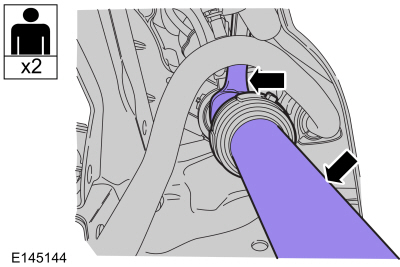
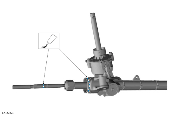
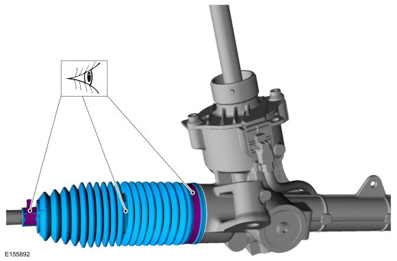
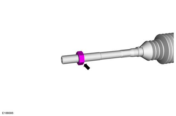
NOTICE: Make sure the end of the steering gear bellows boot is positioned between the 2 grooves on the inner tie rod or an internal leak may occur.
Install the new steering gear bellows boot and new clamps.
Use the General Equipment: Boot Clamp Pliers
 |
-
Thread the tie rod end jam nut onto the tie rod.
 |
-
If equipped
Position the steering gear heat shield and install the retainers.
Torque: 71 lb.in (8 Nm)
|
-
If equipped.
Install the dual under body shields and the retainers.
|
-
If equipped.
Install the under body shield and the retainers.
|
-
Install the tie rod end.
Refer to: Tie Rod End (211-02 Power Steering, Removal and Installation).
-
Install the wheel and tire.
Refer to: Wheel and Tire (204-04A Wheels and Tires, Removal and Installation).
-
Connect the battery ground cable.
 Steering Gear. Removal and Installation
Removal
NOTE:
Removal steps in this procedure may contain installation details.
If installing a new steering gear, upload the PSCM configuration to the scan tool...
 Tie Rod End. Removal and Installation
Special Tool(s) /
General Equipment
Tie Rod End Remover
Removal
NOTE:
Removal steps in this procedure may contain installation details.
NOTICE:
Disconnect the battery ground cable anytime the
steering linkage is being serviced or damage to the steering gear may
occur resulting in steering gear replacement...
Other information:
Lincoln Nautilus 2018-2026 Service Manual: Front Drive Halfshafts. Diagnosis and Testing
Preliminary Inspection Visually inspect the CV joints, housing, boots, and clamps for obvious signs of mechanical damage. If an obvious cause for an observed or reported concern is found, correct the cause (if possible) before proceeding to the next step If the cause is not visually evident, verify the symptom and REFER to Symptom Chart: NVH...
Lincoln Nautilus 2018-2026 Owners Manual: Catalytic Converter
What Is the Catalytic Converter The catalytic converter is part of your vehicle's emissions system and filters harmful pollutants from the exhaust gas. Catalytic Converter Precautions WARNING: Do not park, idle or drive your vehicle on dry grass or other dry ground cover...
Categories
- Manuals Home
- 1st Generation Nautilus Owners Manual
- 1st Generation Nautilus Service Manual
- Engine Oil Capacity and Specification - 2.0L
- Programming the Garage Door Opener to Your Garage Door Opener Motor
- Child Safety Locks
- New on site
- Most important about car
Programming the Garage Door Opener to Your Garage Door Opener Motor