Lincoln Nautilus: Rear Suspension / Toe Link. Removal and Installation
Lincoln Nautilus 2018-2026 Service Manual / Chassis / Suspension / Rear Suspension / Toe Link. Removal and Installation
Special Tool(s) / General Equipment
| Vehicle/Axle Stands |
Removal
NOTICE: Suspension fasteners are critical parts that affect the performance of vital components and systems. Failure of these fasteners may result in major service expense. Use the same or equivalent parts if replacement is necessary. Do not use a replacement part of lesser quality or substitute design. Tighten fasteners as specified.
-
Remove the wheel and tire.
Refer to: Wheel and Tire (204-04A Wheels and Tires, Removal and Installation).
-
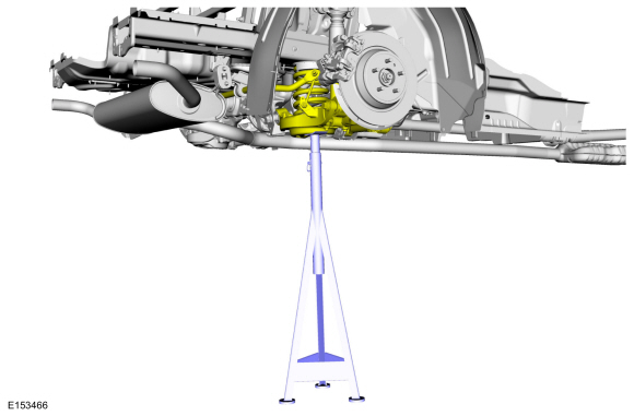
Raise the suspension to curb height.
Use the General Equipment: Vehicle/Axle Stands
 |
-
-
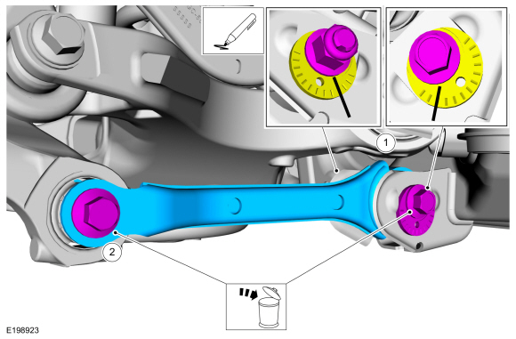
NOTE: Index mark the cam adjusters for reference during installation.
Remove and discard the toe link inboard cam bolt and nut.
-
Remove and discard the toe link outboard bolt and remove the toe link.
-
 |
Installation
-
NOTICE: Tighten the suspension bushing fasteners with the suspension loaded or with the weight of the vehicle resting on the wheels and tires, otherwise incorrect clamp load and bushing damage may occur.
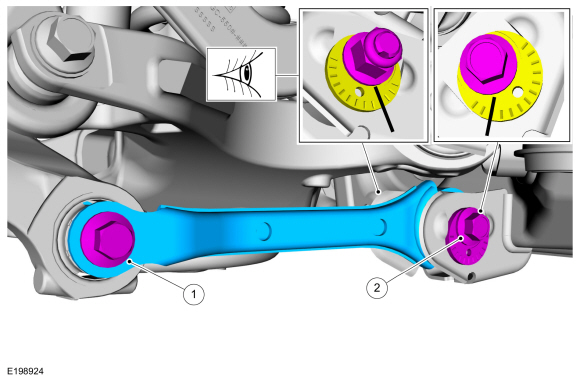
NOTE: Align reference marks made during removal.
-
Install the toe link and install the new outboard toe link bolt.
Torque: 129 lb.ft (175 Nm)
-
Install the new toe link inboard cam bolt and nut.
Torque: 129 lb.ft (175 Nm)
-
Install the toe link and install the new outboard toe link bolt.
 |
-
Install the wheel and tire.
Refer to: Wheel and Tire (204-04A Wheels and Tires, Removal and Installation).
-
Check and if necessary adjust rear toe.
Refer to: Rear Toe Adjustment (204-00 Suspension System - General Information, General Procedures).
 Spring. Removal and Installation
Special Tool(s) /
General Equipment
Spring Compressor
Vise
Removal
NOTICE:
Suspension fasteners are critical parts that affect the
performance of vital components and systems...
 Upper Arm. Removal and Installation
Special Tool(s) /
General Equipment
Vehicle/Axle Stands
Removal
NOTICE:
Suspension fasteners are critical parts that affect the
performance of vital components and systems...
Other information:
Lincoln Nautilus 2018-2026 Service Manual: Battery Monitoring Sensor. Removal and Installation
Removal NOTE: When the battery is disconnected and connected, some abnormal drive symptoms may occur while the vehicle relearns its adaptive strategy. The vehicle may need to be driven to allow the PCM to relearn the adaptive strategy values. NOTE: The cowl panel is removed for clarity only...
Lincoln Nautilus 2018-2026 Owners Manual: Power Outlet - Vehicles With: 110V Power Outlet
What Is the Power Outlet The power outlet can power devices that use a household plug. Power Outlet Precautions WARNING: Do not keep electrical devices plugged in the power point whenever the device is not in use. Do not use any extension cord with the 110 volt AC power point, since it will defeat the safety protection design...
Categories
- Manuals Home
- 1st Generation Nautilus Owners Manual
- 1st Generation Nautilus Service Manual
- Auto-Start-Stop
- Switching the Lane Keeping System On and Off. Switching the Lane Keeping System Mode
- Engine Oil Capacity and Specification - 2.0L
- New on site
- Most important about car
Programming the Garage Door Opener to Your Garage Door Opener Motor
Copyright © 2026 www.linautilus.com