Lincoln Nautilus: Wheels and Tires / Wheel and Tire. Disassembly and Assembly
Special Tool(s) / General Equipment
| Wooden Block |
DISASSEMBLY
NOTICE: Failure to follow the instructions below may result in damage to the TPMS .
NOTICE: The TPMS sensor is mounted to the valve stem. Removal of the valve stem requires dismounting the tire from the wheel and removal of the TPMS sensor.
NOTE: Use only the Digital Tire Pressure Gauge any time tire pressures are measured to be sure that accurate values are obtained.
-
Remove the wheel and tire.
Refer to: Wheel and Tire (204-04A Wheels and Tires, Removal and Installation).
-
NOTICE: The valve stem is connected to the TPMS sensor. Do not pull the valve stem from the wheel, or damage to the sensor will occur.
NOTE: If a new TPMS sensor is being installed, remove and discard the valve stem-to-sensor screw and the sensor.
Remove the valve stem core and fully deflate all air from the tire.
-
NOTICE: Do not allow the tire beads to move beyond the wheel mid-plane (middle of the wheel) when separating the beads from the wheels, damage to the TPMS sensor may occur.
NOTICE: Tire and valve stem position is critical to prevent damage to theTPMS sensor when using a paddle-type bead separator.
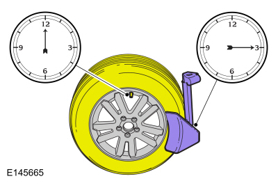
NOTE: Some machines may have a nylon roller bead separator at the 12 o'clock position instead of the paddle-type bead separator at the 3 o'clock position.
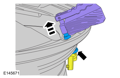
- For a paddle-type tire machine, position the valve stem at the 12 o'clock or 6 o'clock position and the paddle at the 3 o'clock position.
- For a roller-type tire machine, align the valve stem with the roller at any position.
NOTE: Paddle type shown, roller type similar.
 |
-
NOTE: Index-mark the valve stem and wheel weight positions on the tire.
Place the wheel and tire assembly on the turntable of the tire machine with the valve stem at the 11:30 position and the machine arm at the 12 o'clock position and dismount the outer bead from the wheel.
 |
-
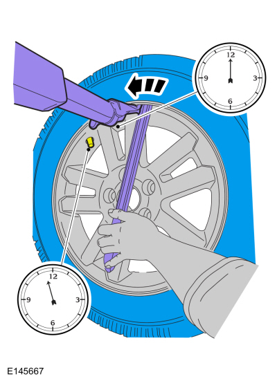
Reset the wheel and tire assembly on the turntable of
the tire machine with the valve stem at the 11:30 position and the
machine arm at the 12 o'clock position and dismount the inner bead from
the wheel.
-
NOTE: A new valve stem must be installed whenever a new tire or wheel is installed.
-
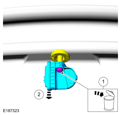
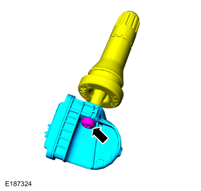
Remove and discard the TPMS sensor-to-valve stem screw.
-
Separate the TPMS sensor from the valve stem.
-
Remove and discard the TPMS sensor-to-valve stem screw.
 |
-
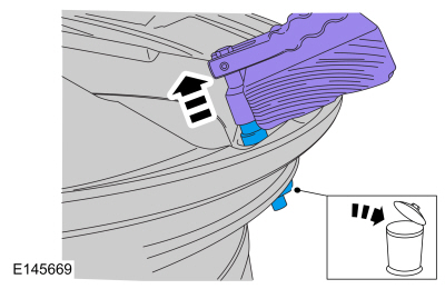
NOTICE: Use care not to damage the wheel surface when removing the valve stem.
Using a suitable valve stem remover/installer, remove and discard the valve stem.
Use the General Equipment: Wooden Block
 |
NOTE: When installing a new wheel, always install a new valve stem and sensor screw. Reuse theTPMS sensor from the previous wheel if possible. The TPMS will not have to be trained if the sensor is reused.
NOTE: If the TPMS sensor is being reused, inspect the TPMS sensor for damage and install a new sensor as necessary.
-
NOTICE: To prevent TPMS sensor and valve stem damage, the valve stem must be installed onto the TPMS sensor and then installed into the wheel as an assembly.
Position the new valve stem onto the TPMS sensor and install the new screw.
Torque: 13 lb.in (1.5 Nm)
 |
ASSEMBLY
NOTICE: Damage to the TPMS sensor may result if the tire mounting is not carried out as instructed.
-
NOTICE: It is important to pull the valve stem and TPMS sensor assembly through the wheel rim hole in a direction parallel to the valve stem hole axis. If the assembly is pulled through at an angle, damage to the valve stem and sensor assembly may occur.
NOTICE: Use care not to damage the wheel surface when installing the valve stem and TPMS sensor assembly.
NOTE: Lubricate the valve stem with soapy water and install the valve stem and TPMS sensor assembly into the wheel using a block of wood and a suitable valve stem installer.
Using a suitable valve stem installer, install the new valve stem and TPMS sensor assembly.
Use the General Equipment: Wooden Block
 |
-
NOTE: Lubricate the tire beads using a suitable fast-drying, corrosion-inhibiting tire bead lubricant.
NOTE: Do not mount the tire at this time.
Position the wheel on the turntable of the tire machine, then lubricate and position the bottom bead of the tire on the wheel.
-
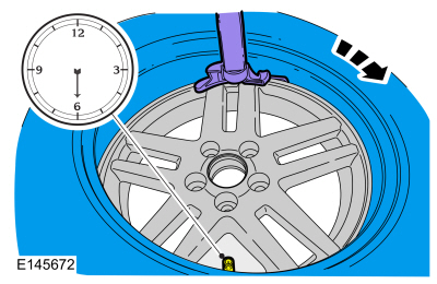
Position the wheel to align the valve stem with the
machine arm, at the 6 o'clock position, and mount the bottom bead of the
tire.
 |
-
Reposition the wheel to align the valve stem with the
machine arm at the 6 o'clock position, and mount the top bead of the
tire.
-
NOTE: Use only the Digital Tire Pressure Gauge any time tire pressures are measured to be sure that accurate values are obtained.
Inflate the tire to the pressure specified on the VC label located on the driver door or door pillar.
NOTE: Proceed to the next step if the tire beads do not seat at the specified inflation pressure.
-
 WARNING:
If there is a need to exceed the maximum pressure
indicated on the sidewall of the tire in order to seat the beads, follow
all steps listed below. Failure to follow these steps may result in
serious personal injury.
WARNING:
If there is a need to exceed the maximum pressure
indicated on the sidewall of the tire in order to seat the beads, follow
all steps listed below. Failure to follow these steps may result in
serious personal injury.
NOTICE: The following steps should only be carried out if the tire beads cannot be seated by inflating the tire up to the maximum inflation pressure listed on the tire sidewall.
-
Relubricate the tire bead and wheel bead seat area.
-
Install a remote valve and pressure gauge.
-
Wear eye and ear protection and stand at a minimum of 3.65 m (12 ft) away from the wheel and tire assembly.
-
Inflate the tire using the remote valve and tire
gauge until the beads have seated or until the pressure gauge is 138 kPa
(20 psi) more than maximum inflation pressure on tire sidewall. If
beads have not seated, deflate the tire and proceed to the next step.
-
Place the wheel and tire assembly in an OSHA-approved tire safety cage.
-
Inflate the tire using the remote valve and pressure
gauge until the beads have seated or until the pressure gauge is 276
kPa (40 psi) more than maximum inflation pressure on the tire sidewall. Do
not exceed 276 kPa (40 psi) above the maximum pressure on tire
sidewall. Install a new tire if the beads do not seat at this pressure.
-
Relubricate the tire bead and wheel bead seat area.
-
Install the wheel and tire.
Refer to: Wheel and Tire (204-04A Wheels and Tires, Removal and Installation).
 Wheel and Tire. Removal and Installation
Materials
Name
Specification
Motorcraft® High Temperature Nickel Anti-Seize LubricantXL-2
-
Motorcraft® Wheel and Tire CleanerZC-37-A
-
Removal
With the vehicle in NEUTRAL, position it on a hoist...

Other information:
Lincoln Nautilus 2018-2026 Owners Manual: Principle of Operation
MyKey allows you to program keys with restricted driving modes to promote good driving habits. All but one of the keys can be activated with these restricted modes. Any keys that remain unprogrammed are referred to as administrator keys or admin keys. They can be used to: Create a MyKey. Program configurable MyKey settings. Clear all MyKey features. When you have created a MyKey, you can..
Lincoln Nautilus 2018-2026 Service Manual: Ethernet Module Communications Network - System Operation and Component Description. Description and Operation
System Operation Overview The Ethernet communication network is a high speed communication network providing high bandwidth data transfer and improved data security to support module updates over the air, driver assistance systems, multi media systems and improved connectivity. The Ethernet communication network connects the TCU and the GWM and other connected modules such as the APIM an..
Categories
- Manuals Home
- 1st Generation Nautilus Owners Manual
- 1st Generation Nautilus Service Manual
- Opening the Liftgate
- Fuel Quality
- Anti-Theft Alarm System Settings. Security – Troubleshooting
- New on site
- Most important about car
Replacing the Rear Wiper Blades
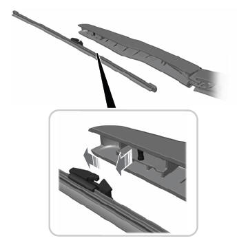
Note: Do not hold the wiper blade to lift the wiper arm.
Remove the wiper blade.