Lincoln Nautilus: Wheels and Tires / Wheel to Tire Runout Minimization. General Procedures
Check
NOTE: Road Force® values in illustrations are shown in pounds.
NOTE: Match mounting is a technique used to reduce radial runout or road force on wheel and tire assemblies. Excessive runout is a source of ride quality complaints and match mounting can be used to minimize the runout. Match mounting can be accomplished by changing the position of the tire on the wheel.
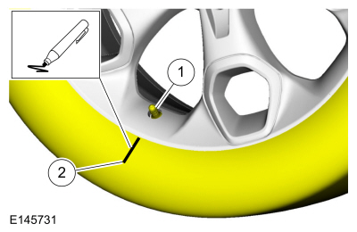
NOTE: Position the wheel and tire assembly on a tire machine and put a reference mark on the tire sidewall at the valve stem position.
-
-
Valve stem.
-
Reference mark.
-
Valve stem.
 |
-
NOTICE: For vehicles equipped with a TPMS , the sensor may be damaged by incorrect tire mounting or dismounting. Dismount the tire from the wheel as instructed in the procedure. Failure to follow these instructions may result in TPMS component damage.
NOTE: Always make sure that the final high spot and measurement values are permanently marked on the inward sidewall of the tire for reference during future wheel and tire service.
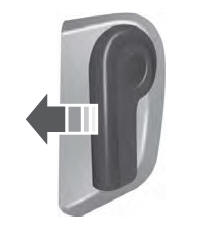
Marker. Using a suitable tire machine, separate the tire beads from the wheel.
-
Lubricate the tire beads using a suitable fast drying,
corrosion inhibiting tire bead lubricant. Position the tire 180 degrees
(half-way around) on the rim so the valve stem reference mark is now
opposite the valve stem.
-
Re-inflate the wheel and tire assembly to the specified
air pressure and measure the assembly again using a suitable dial
indicator or Hunter Road Force® 9700 Series Wheel Balancer. Mark the
second high spot on the tire.
-
If the runout or Road Force is reduced to within
specifications, the concern has been resolved. Balance the assembly and
install on the vehicle using the Wheel-to-Hub Optimization procedure.
-
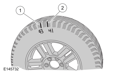
If the second runout or Road Force® measurement is still
not within specification and both high spots are close to each other
(within 101.6 mm [4 in]), the root cause is probably the tire (the high
spot followed the tire).
-
-
First high spot on the tire.
-
Second high spot on the tire.
-
First high spot on the tire.
 |
-
To be SURE that the tire is causing the high runout, it
is necessary to have 2 runout or Road Force® measurements that are not
within specification and the high spots must be in approximately the
same location on the tire's sidewall. If the tire is the cause, install a
new tire, balance the assembly and install on the vehicle using the
Wheel-to-Hub Optimization procedure. If the second high spot is not
within 101.6 mm (4 in) of the first high spot, proceed to the next step.
-
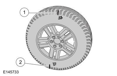
If the second high spot is still above specification and
is within 101.6 mm (4 in) of being opposite the first high spot on the
wheel, the root cause is probably the wheel (the high spot followed the
wheel). Dismount the tire from the wheel, mount the wheel on a balancer
and check the wheel runout. If the wheel runout exceeds 1.14 mm (0.0449
in), install a new wheel, balance the assembly and install on the
vehicle using the Wheel-to-Hub Optimization procedure.
Refer to: Wheel to Hub Runout Minimization (204-04A Wheels and Tires, General Procedures).
-
-
First high spot on the tire.
-
Second high spot on the tire.
-
First high spot on the tire.
 |
-
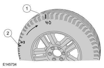
NOTE: If the second high spot did not follow the wheel or the tire and the runout is still not within specification, improvements may be made by rotating the tire 90 degrees (one-fourth turn).
Draw an arrow on the tire sidewall from the second high spot towards the first high spot (in the shortest direction).
-
-
First high spot on the tire
-
Second high spot on the tire
-
First high spot on the tire
 |
-
Separate the tire beads from the wheel and rotate the
tire 90 degrees (one-fourth turn) in the direction of the arrow.
 Wheel to Hub Runout Minimization. General Procedures
Check
NOTE:
Wheel-to-hub optimization is important. Clearance between
the wheel and hub can be used to offset or neutralize the Road Force® or
run-out of the wheel and tire assembly...
 Wheel and Tire. Removal and Installation
Materials
Name
Specification
Motorcraft® High Temperature Nickel Anti-Seize LubricantXL-2
-
Motorcraft® Wheel and Tire CleanerZC-37-A
-
Removal
With the vehicle in NEUTRAL, position it on a hoist...
Other information:
Lincoln Nautilus 2018-2026 Service Manual: Anti-Lock Brake System (ABS) Module. Removal and Installation
Removal NOTE: Removal steps in this procedure may contain installation details. NOTE: The ABS module and HCU are released individually. A new ABS module does not come equipped with an HCU . NOTE: The PMI process must begin with the current ABS module installed...
Lincoln Nautilus 2018-2026 Service Manual: Parking Aid - Component Location. Description and Operation
Component Location - Parking Aid Camera Item Description 1 Rear parking aid camera 2 FDIM 3 LH side parking aid camera (360 degree view camera system) 4 BCM (rear only parking aid camera system) 5 Front parking aid camera assembly (360 degree view camera system) 6 IPMB (360 degree view camera system) 7 RH side parking aid came..
Categories
- Manuals Home
- 1st Generation Nautilus Owners Manual
- 1st Generation Nautilus Service Manual
- Drive Mode Control
- Switching the Lane Keeping System On and Off. Switching the Lane Keeping System Mode
- Engine Oil Capacity and Specification - 2.0L
- New on site
- Most important about car
Opening and Closing the Hood
Opening the Hood