Lincoln Nautilus: General Information / Wire Terminal Inspection and Removal. General Procedures
Disconnect
-
Refer to: Health and Safety Precautions (100-00 General Information, Description and Operation). WARNING:
Before beginning any service procedure in this
section, refer to Health and Safety Precautions in section 100-00
General Information. Failure to follow this instruction may result in
serious personal injury.
WARNING:
Before beginning any service procedure in this
section, refer to Health and Safety Precautions in section 100-00
General Information. Failure to follow this instruction may result in
serious personal injury.
NOTE: To avoid wiring pin (terminal) damage, Rotunda Flex Probes NUD105-R025D or Terminal Probe Kit 29-011A must be used to connect test equipment or jumper wires to pins (terminals).
- Male to female pin (terminal) fit is critical for correct connection and durability.
- Pin (terminal) fit may be checked by using the mating pin (terminal) to test for normal separation force (a damaged pin or terminal will have very low separation force from the mating pin or terminal).
- Correctly checking the separation force of small pins (terminals) may require removal of the connector terminal guide/retainer if it adds drag to the pin (terminal) insertion or removal.
- For more detail on the replacement of damaged connectors or pins (terminals) refer to the video below.
Click here to view a video version of this procedure.

-
NOTE: The connector hard-shell information, which is measured in millimeters is the distance from the front face of the connector to the engagement point on the terminal release tang. Mark the listed distance on the terminal removal tool prior to removing the terminal.
NOTE: The dimensions of the connector hard-shell and the connector terminals release tang are listed above the corresponding graphics.
-
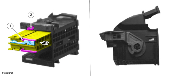
Audio Front Control Module (ACM), Body Control Module (BCM) and Instrument Panel Cluster (IPC) Electrical Connector
Callout Connector 1 External terminal release tang 2 Electrical connector locking tab
 |
-
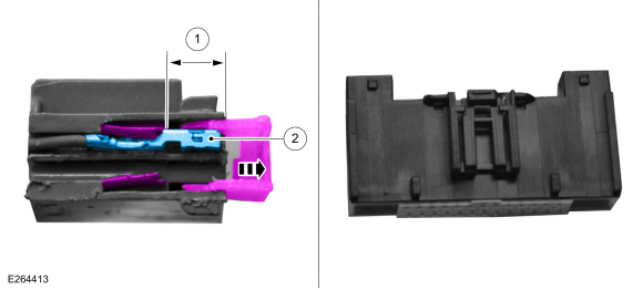
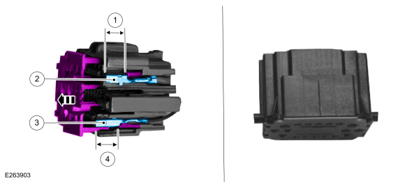
Audio Front Control Module (ACM), Front Controls Interface Module (FCIM), Gateway Module A (GWM), and Heating, Ventilation and Air Conditioning (HVAC) Control Module Electrical Connector
Callout Connector 1 Distance to release tang - 0.2953 in ( 7.5 mm) (inner terminal) - 0.4646 in ( 11.8 mm) (outer terminal) 2 Terminal width size - 0.0244 in ( .62 mm) (inner terminal) - 0.1102 in ( 2.8 mm) (outer terminal)
 |
-
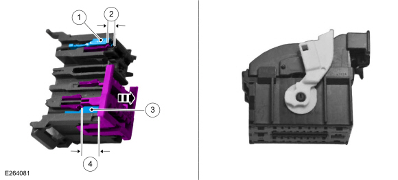
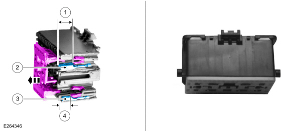
Body Control Module (BCM) Electrical Connector
Callout Connector 1 Terminal width size - 0.1102 in ( 2.8 mm) (inner terminal) - 0.2480 in ( 6.3 mm) (outer terminal) 2 Distance to release tang - 0.1260 in ( 3.2 mm) (inner terminal) - 0.1575 in ( 4 mm) (outer terminal) 3 Terminal width size - 0.0591 in ( 1.5 mm) 4 Distance to release tang - 0.3780 in ( 9.6 mm) (lower terminal)
 |
-
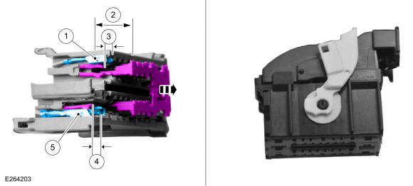
Body Control Module (BCM) Electrical Connector
Callout Connector 1 Terminal width size - 0.0591 in ( 1.5 mm) (inner terminal) - 0.1102 in ( 2.8 mm) (outer terminal) 2 Distance to release tang - 0.3780 in ( 9.6 mm) (inner terminal) 3 Distance to release tang - 0.1575 in ( 4 mm) 4 Distance to release tang - 0.1575 in ( 4 mm) 5 Terminal width size - 0.2480 in ( 6.3 mm)
 |
-
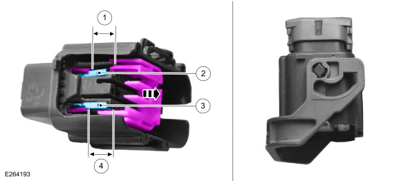
Body Harness In-line Electrical Connector
Callout Connector 1 Distance to release tang - 0.3346 in ( 8.5 mm) 2 Terminal width size - 0.1102 in ( 2.8 mm) 3 Terminal width size - 0.0591 in ( 1.5 mm) 4 Distance to release tang - 0.3858 in ( 9.8 mm) (inner)
 |
-
Body Harness In-line Electrical Connector
Callout Connector 1 Distance to release tang - 0.3543 in ( 9 mm) 2 Terminal width size - 0.0591 in ( 1.5 mm) (inner terminal) - 0.1102 in ( 2.8 mm) (outer terminal) 3 Terminal width size - 0.2480 in ( 6.3 mm) 4 Distance to release tang - 0.3543 in ( 9 mm)
 |
-
Body Harness In-line and Seat Harness Electrical Connector
Callout Connector 1 Distance to release tang - 0.4331 in ( 11 mm) 2 Terminal width size - 0.0591 in ( 1.5 mm) 3 Terminal width size - 0.0591 in ( 1.5 mm) 4 Distance to release tang - 0.4331 in ( 11 mm)
 |
-
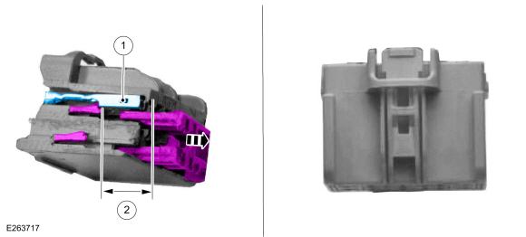
Body Harness In-line and Seat Module Electrical Connector
Callout Connector 1 Terminal width size - 0.0591 in ( 1.5 mm) 2 Distance to release tang - 0.3937 in ( 10 mm)
 |
 Diagnostic Trouble Code Charts. Diagnosis and Testing
Master DTC Index
Module
Section
ABS module
REFER to: Anti-Lock Brake System (ABS) and Stability Control
(206-09 Anti-Lock Brake System (ABS) and Stability Control, Diagnosis
and Testing)...

Other information:
Lincoln Nautilus 2018-2026 Service Manual: Sealer, Underbody Protection Material and Adhesives. Description and Operation
Adhesives NOTE: The following illustrations are examples of structural adhesive application and are not all inclusive. The correct adhesive bonding is essential to repairing the vehicle correctly. Adhesives are used in many areas of the body structure in place of welding. In addition to providing a structural bond between component, adhesives can also help prevent wind noise, water leak..
Lincoln Nautilus 2018-2026 Service Manual: Lower Arm Vertical Link. Removal and Installation
Special Tool(s) / General Equipment Vehicle/Axle Stands Removal NOTICE: Suspension fasteners are critical parts that affect the performance of vital components and systems. Failure of these fasteners may result in major service expense. Use the same or equivalent parts if replacement is necessary. Do not use a replacement part of lesser quality or substitute design. Tighten fast..
Categories
- Manuals Home
- 1st Generation Nautilus Owners Manual
- 1st Generation Nautilus Service Manual
- Normal Scheduled Maintenance
- Folding the Exterior Mirrors - Vehicles With: Manual Folding Mirrors. Folding the Exterior Mirrors - Vehicles With: Power Folding Mirrors
- Drive Mode Control
- New on site
- Most important about car
Parking Aid Indicators. Parking Aids – Troubleshooting
Parking Aid Indicators
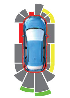
The system provides object distance indication through the information and entertainment display.
As the distance to the object decreases, the indicator waves and the lines move toward the vehicle icon. If there is no object detected, the distance indicator lines are grey.