Lincoln Nautilus: Supplemental Restraint System / Airbag Supplemental Restraint System (SRS). Diagnosis and Testing
Diagnostic Trouble Code (DTC) Chart
Diagnostics in this manual assume a certain skill level and knowledge of Ford-specific diagnostic practices.
REFER to: Diagnostic Methods (100-00 General Information, Description and Operation).
NOTE: Unlisted Diagnostic Trouble Codes (DTCs) are often retrieved as a result of incorrect repair procedures. Before attempting any repairs for unlisted Diagnostic Trouble Codes (DTCs), check the vehicle service history for recent repairs. For RCM Diagnostic Trouble Codes (DTCs) not listed in this chart,
- Repair all other RCM Diagnostic Trouble Codes (DTCs) before attempting to repair any Diagnostic Trouble Codes (DTCs) not listed in this chart.
- If no other RCM Diagnostic Trouble Codes (DTCs) are retrieved, CLEAR the RCM Diagnostic Trouble Codes (DTCs) and REPEAT the self-test. If the RCM Diagnostic Trouble Codes (DTCs) return, VERIFY that the RCM is the correct part number for the vehicle application, and INSTALL As-Built data following scan tool instructions under Module Programming > As-Built.
- Inspect the RCM and RCM connectors for any damaged pins or connections.
| Module | DTC | Description | Action |
|---|---|---|---|
| BCM | B11D8:01 | Restraint Event Notification: General Electrical Failure | GO to Pinpoint Test BH |
| DDM | B1262:92 | Crash Input Mismatch - CAN Active, Hardware Inactive: Performance Or Incorrect Operation | GO to Pinpoint Test BH |
| HVAC | B00D5:01 | Restraint System Passenger Disable Indicator: General Electrical Failure | GO to Pinpoint Test Q |
| HVAC | B1202:01 | Restraint System Passenger Enable Indicator: General Electrical Failure | GO to Pinpoint Test R |
| OCSM | B0061:11 | Passenger Seatbelt Tension Sensor: Circuit Short To Ground | GO to Pinpoint Test AX |
| OCSM | B0061:12 | Passenger Seatbelt Tension Sensor: Circuit Short To Battery | GO to Pinpoint Test AX |
| OCSM | B0061:13 | Passenger Seatbelt Tension Sensor: Circuit Open | GO to Pinpoint Test AX |
| OCSM | B0061:64 | Passenger Seatbelt Tension Sensor: Signal Plausibility Failure | GO to Pinpoint Test AX |
| OCSM | B00A0:62 | Occupant Classification System: Signal Compare Failure | GO to Pinpoint Test AZ |
| OCSM | B00C0:11 | Passenger Seat Occupant Classification Sensor 'A': Circuit Short To Ground | GO to Pinpoint Test AY |
| OCSM | B00C0:12 | Passenger Seat Occupant Classification Sensor 'A': Circuit Short To Battery | GO to Pinpoint Test AY |
| OCSM | B00C0:16 | Passenger Seat Occupant Classification Sensor 'A': Circuit Voltage Below Threshold | GO to Pinpoint Test AY |
| OCSM | B00C0:49 | Passenger Seat Occupant Classification Sensor 'A': Internal Electronic Failure | GO to Pinpoint Test AY |
| OCSM | B00C0:7B | Passenger Seat Occupant Classification Sensor 'A': Low Fluid Level | GO to Pinpoint Test AY |
| OCSM | B00C2:11 | Passenger Seat Occupant Classification Sensor 'C': Circuit Short To Ground | GO to Pinpoint Test BA |
| OCSM | B00C2:12 | Passenger Seat Occupant Classification Sensor 'C': Circuit Short To Battery | GO to Pinpoint Test BA |
| OCSM | B1193:00 | Crash Event Storage Full and Locked: No Sub Type Information | GO to Pinpoint Test BB |
| OCSM | U0100:00 | Lost Communication With ECM/PCM 'A': No Sub Type Information | GO to Pinpoint Test BC |
| OCSM | U0151:00 | Lost Communication With Restraints Control Module: No Sub Type Information | GO to Pinpoint Test BD |
| OCSM | U0401:00 | Invalid Data Received from ECM/PCM A: No Sub Type Information | GO to Pinpoint Test BE |
| OCSM | U3000:41 | Control Module: General Checksum Failure | GO to Pinpoint Test BF |
| OCSM | U3000:42 | Control Module: General Memory Failure | GO to Pinpoint Test BF |
| OCSM | U3000:46 | Control Module: Calibration/Parameter Memory Failure | GO to Pinpoint Test BF |
| OCSM | U3000:54 | Control Module: Missing Calibration | GO to Pinpoint Test BG |
| OCSM | U3003:16 | Battery Voltage: Circuit Voltage Below Threshold | GO to Pinpoint Test AW |
| OCSM | U3003:17 | Battery Voltage: Circuit Voltage Above Threshold | GO to Pinpoint Test AW |
| PDM | B1262:92 | Crash Input Mismatch - CAN Active, Hardware Inactive: Performance Or Incorrect Operation | GO to Pinpoint Test BH |
| RCM | B0001:11 | Driver Frontal Stage 1 Deployment Control: Circuit Short To Ground | GO to Pinpoint Test A |
| RCM | B0001:12 | Driver Frontal Stage 1 Deployment Control: Circuit Short To Battery | GO to Pinpoint Test A |
| RCM | B0001:13 | Driver Frontal Stage 1 Deployment Control: Circuit Open | GO to Pinpoint Test A |
| RCM | B0001:1A | Driver Frontal Stage 1 Deployment Control: Circuit Resistance Below Threshold | GO to Pinpoint Test A |
| RCM | B0001:2B | Driver Frontal Stage 1 Deployment Control: Signal Cross-Coupled | GO to Pinpoint Test AI |
| RCM | B0001:4A | Driver Frontal Stage 1 Deployment Control: Incorrect Component Installed | GO to Pinpoint Test AJ |
| RCM | B0002:11 | Driver Frontal Stage 2 Deployment Control: Circuit Short To Ground | GO to Pinpoint Test B |
| RCM | B0002:12 | Driver Frontal Stage 2 Deployment Control: Circuit Short To Battery | GO to Pinpoint Test B |
| RCM | B0002:13 | Driver Frontal Stage 2 Deployment Control: Circuit Open | GO to Pinpoint Test B |
| RCM | B0002:1A | Driver Frontal Stage 2 Deployment Control: Circuit Resistance Below Threshold | GO to Pinpoint Test B |
| RCM | B0002:2B | Driver Frontal Stage 2 Deployment Control: Signal Cross-Coupled | GO to Pinpoint Test AI |
| RCM | B0002:4A | Driver Frontal Stage 2 Deployment Control: Incorrect Component Installed | GO to Pinpoint Test AJ |
| RCM | B0004:11 | Driver Knee Bolster Deployment Control: Circuit Short To Ground | GO to Pinpoint Test C |
| RCM | B0004:12 | Driver Knee Bolster Deployment Control: Circuit Short To Battery | GO to Pinpoint Test C |
| RCM | B0004:13 | Driver Knee Bolster Deployment Control: Circuit Open | GO to Pinpoint Test C |
| RCM | B0004:1A | Driver Knee Bolster Deployment Control: Circuit Resistance Below Threshold | GO to Pinpoint Test C |
| RCM | B0004:2B | Driver Knee Bolster Deployment Control: Signal Cross-Coupled | GO to Pinpoint Test AI |
| RCM | B0004:4A | Driver Knee Bolster Deployment Control: Incorrect Component Installed | GO to Pinpoint Test AJ |
| RCM | B0010:11 | Passenger Frontal Stage 1 Deployment Control: Circuit Short To Ground | GO to Pinpoint Test D |
| RCM | B0010:12 | Passenger Frontal Stage 1 Deployment Control: Circuit Short To Battery | GO to Pinpoint Test D |
| RCM | B0010:13 | Passenger Frontal Stage 1 Deployment Control: Circuit Open | GO to Pinpoint Test D |
| RCM | B0010:1A | Passenger Frontal Stage 1 Deployment Control: Circuit Resistance Below Threshold | GO to Pinpoint Test D |
| RCM | B0010:2B | Passenger Frontal Stage 1 Deployment Control: Signal Cross-Coupled | GO to Pinpoint Test AI |
| RCM | B0010:4A | Passenger Frontal Stage 1 Deployment Control: Incorrect Component Installed | GO to Pinpoint Test AJ |
| RCM | B0011:11 | Passenger Frontal Stage 2 Deployment Control: Circuit Short To Ground | GO to Pinpoint Test E |
| RCM | B0011:12 | Passenger Frontal Stage 2 Deployment Control: Circuit Short To Battery | GO to Pinpoint Test E |
| RCM | B0011:13 | Passenger Frontal Stage 2 Deployment Control: Circuit Open | GO to Pinpoint Test E |
| RCM | B0011:1A | Passenger Frontal Stage 2 Deployment Control: Circuit Resistance Below Threshold | GO to Pinpoint Test E |
| RCM | B0011:2B | Passenger Frontal Stage 2 Deployment Control: Signal Cross-Coupled | GO to Pinpoint Test AI |
| RCM | B0011:4A | Passenger Frontal Stage 2 Deployment Control: Incorrect Component Installed | GO to Pinpoint Test AJ |
| RCM | B0013:11 | Passenger Knee Bolster Deployment Control: Circuit Short To Ground | GO to Pinpoint Test F |
| RCM | B0013:12 | Passenger Knee Bolster Deployment Control: Circuit Short To Battery | GO to Pinpoint Test F |
| RCM | B0013:13 | Passenger Knee Bolster Deployment Control: Circuit Open | GO to Pinpoint Test F |
| RCM | B0013:1A | Passenger Knee Bolster Deployment Control: Circuit Resistance Below Threshold | GO to Pinpoint Test F |
| RCM | B0013:2B | Passenger Knee Bolster Deployment Control: Signal Cross-Coupled | GO to Pinpoint Test AI |
| RCM | B0013:4A | Passenger Knee Bolster Deployment Control: Incorrect Component Installed | GO to Pinpoint Test AJ |
| RCM | B0050:11 | Driver Seatbelt Sensor: Circuit Short To Ground | GO to Pinpoint Test G |
| RCM | B0050:12 | Driver Seatbelt Sensor: Circuit Short To Battery | GO to Pinpoint Test G |
| RCM | B0050:13 | Driver Seatbelt Sensor: Circuit Open | GO to Pinpoint Test G |
| RCM | B0050:1D | Driver Seatbelt Sensor: Circuit Current Out Of Range | GO to Pinpoint Test G |
| RCM | B0050:2B | Driver Seatbelt Sensor: Signal Cross-Coupled | GO to Pinpoint Test AI |
| RCM | B0050:4A | Driver Seatbelt Sensor: Incorrect Component Installed | GO to Pinpoint Test AJ |
| RCM | B0052:11 | Passenger Seatbelt Sensor: Circuit Short To Ground | GO to Pinpoint Test H |
| RCM | B0052:12 | Passenger Seatbelt Sensor: Circuit Short To Battery | GO to Pinpoint Test H |
| RCM | B0052:13 | Passenger Seatbelt Sensor: Circuit Open | GO to Pinpoint Test H |
| RCM | B0052:1D | Passenger Seatbelt Sensor: Circuit Current Out Of Range | GO to Pinpoint Test H |
| RCM | B0052:2B | Passenger Seatbelt Sensor: Signal Cross-Coupled | GO to Pinpoint Test AI |
| RCM | B0052:4A | Passenger Seatbelt Sensor: Incorrect Component Installed | GO to Pinpoint Test AJ |
| RCM | B0070:11 | Driver Seatbelt Pretensioner 'A' Deployment Control: Circuit Short To Ground | GO to Pinpoint Test I |
| RCM | B0070:12 | Driver Seatbelt Pretensioner 'A' Deployment Control: Circuit Short To Battery | GO to Pinpoint Test I |
| RCM | B0070:13 | Driver Seatbelt Pretensioner 'A' Deployment Control: Circuit Open | GO to Pinpoint Test I |
| RCM | B0070:1A | Driver Seatbelt Pretensioner 'A' Deployment Control: Circuit Resistance Below Threshold | GO to Pinpoint Test I |
| RCM | B0070:2B | Driver Seatbelt Pretensioner 'A' Deployment Control: Signal Cross-Coupled | GO to Pinpoint Test AI |
| RCM | B0070:4A | Driver Seatbelt Pretensioner 'A' Deployment Control: Incorrect Component Installed | GO to Pinpoint Test AJ |
| RCM | B0072:11 | Passenger Seatbelt Pretensioner 'A' Deployment Control: Circuit Short To Ground | GO to Pinpoint Test J |
| RCM | B0072:12 | Passenger Seatbelt Pretensioner 'A' Deployment Control: Circuit Short To Battery | GO to Pinpoint Test J |
| RCM | B0072:13 | Passenger Seatbelt Pretensioner 'A' Deployment Control: Circuit Open | GO to Pinpoint Test J |
| RCM | B0072:1A | Passenger Seatbelt Pretensioner 'A' Deployment Control: Circuit Resistance Below Threshold | GO to Pinpoint Test J |
| RCM | B0072:2B | Passenger Seatbelt Pretensioner 'A' Deployment Control: Signal Cross-Coupled | GO to Pinpoint Test AI |
| RCM | B0072:4A | Passenger Seatbelt Pretensioner 'A' Deployment Control: Incorrect Component Installed | GO to Pinpoint Test AJ |
| RCM | B007E:11 | Driver Seatbelt Pretensioner 'C' Deployment Control: Circuit Short To Ground | GO to Pinpoint Test K |
| RCM | B007E:12 | Driver Seatbelt Pretensioner 'C' Deployment Control: Circuit Short To Battery | GO to Pinpoint Test K |
| RCM | B007E:13 | Driver Seatbelt Pretensioner 'C' Deployment Control: Circuit Open | GO to Pinpoint Test K |
| RCM | B007E:1A | Driver Seatbelt Pretensioner 'C' Deployment Control: Circuit Resistance Below Threshold | GO to Pinpoint Test K |
| RCM | B007E:2B | Driver Seatbelt Pretensioner 'C' Deployment Control: Signal Cross-Coupled | GO to Pinpoint Test AI |
| RCM | B007E:4A | Driver Seatbelt Pretensioner 'C' Deployment Control: Incorrect Component Installed | GO to Pinpoint Test AJ |
| RCM | B007F:11 | Passenger Seatbelt Pretensioner 'C' Deployment Control: Circuit Short To Ground | GO to Pinpoint Test L |
| RCM | B007F:12 | Passenger Seatbelt Pretensioner 'C' Deployment Control: Circuit Short To Battery | GO to Pinpoint Test L |
| RCM | B007F:13 | Passenger Seatbelt Pretensioner 'C' Deployment Control: Circuit Open | GO to Pinpoint Test L |
| RCM | B007F:1A | Passenger Seatbelt Pretensioner 'C' Deployment Control: Circuit Resistance Below Threshold | GO to Pinpoint Test L |
| RCM | B007F:2B | Passenger Seatbelt Pretensioner 'C' Deployment Control: Signal Cross-Coupled | GO to Pinpoint Test AI |
| RCM | B007F:4A | Passenger Seatbelt Pretensioner 'C' Deployment Control: Incorrect Component Installed | GO to Pinpoint Test AJ |
| RCM | B0082:11 | Passenger Seatbelt Load Limiter Deployment Control: Circuit Short To Ground | GO to Pinpoint Test M |
| RCM | B0082:12 | Passenger Seatbelt Load Limiter Deployment Control: Circuit Short To Battery | GO to Pinpoint Test M |
| RCM | B0082:13 | Passenger Seatbelt Load Limiter Deployment Control: Circuit Open | GO to Pinpoint Test M |
| RCM | B0082:1A | Passenger Seatbelt Load Limiter Deployment Control: Circuit Resistance Below Threshold | GO to Pinpoint Test M |
| RCM | B0082:2B | Passenger Seatbelt Load Limiter Deployment Control: Signal Cross-Coupled | GO to Pinpoint Test AI |
| RCM | B0082:4A | Passenger Seatbelt Load Limiter Deployment Control: Incorrect Component Installed | GO to Pinpoint Test AJ |
| RCM | B00A0:09 | Occupant Classification System: Component Failures | GO to Pinpoint Test N |
| RCM | B00A0:4A | Occupant Classification System: Incorrect Component Installed | GO to Pinpoint Test AJ |
| RCM | B00A0:63 | Occupant Classification System: Circuit/Component Protection Time-Out | GO to Pinpoint Test N |
| RCM | B00A0:64 | Occupant Classification System: Signal Plausibility Failure | GO to Pinpoint Test N |
| RCM | B00A0:68 | Occupant Classification System: Event Information | GO to Pinpoint Test N |
| RCM | B00B5:11 | Driver Seat Track Position Restraints Sensor: Circuit Short To Ground | GO to Pinpoint Test O |
| RCM | B00B5:12 | Driver Seat Track Position Restraints Sensor: Circuit Short To Battery | GO to Pinpoint Test O |
| RCM | B00B5:13 | Driver Seat Track Position Restraints Sensor: Circuit Open | GO to Pinpoint Test O |
| RCM | B00B5:1D | Driver Seat Track Position Restraints Sensor: Circuit Current Out Of Range | GO to Pinpoint Test O |
| RCM | B00B5:2B | Driver Seat Track Position Restraints Sensor: Signal Cross-Coupled | GO to Pinpoint Test AI |
| RCM | B00B5:4A | Driver Seat Track Position Restraints Sensor: Incorrect Component Installed | GO to Pinpoint Test AJ |
| RCM | B00C5:11 | Passenger Seat Track Position Restraints Sensor: Circuit Short To Ground | GO to Pinpoint Test P |
| RCM | B00C5:12 | Passenger Seat Track Position Restraints Sensor: Circuit Short To Battery | GO to Pinpoint Test P |
| RCM | B00C5:13 | Passenger Seat Track Position Restraints Sensor: Circuit Open | GO to Pinpoint Test P |
| RCM | B00C5:1D | Passenger Seat Track Position Restraints Sensor: Circuit Current Out Of Range | GO to Pinpoint Test P |
| RCM | B00C5:2B | Passenger Seat Track Position Restraints Sensor: Signal Cross-Coupled | GO to Pinpoint Test AI |
| RCM | B00C5:4A | Passenger Seat Track Position Restraints Sensor: Incorrect Component Installed | GO to Pinpoint Test AJ |
| RCM | B00D5:01 | Restraint System Passenger Disable Indicator: General Electrical Failure | GO to Pinpoint Test Q |
| RCM | B1193:00 | Crash Event Storage Full and Locked: No Sub Type Information | GO to Pinpoint Test S |
| RCM | B11CF:11 | Passenger Frontal Airbag Canister Vent: Circuit Short To Ground | GO to Pinpoint Test T |
| RCM | B11CF:12 | Passenger Frontal Airbag Canister Vent: Circuit Short To Battery | GO to Pinpoint Test T |
| RCM | B11CF:13 | Passenger Frontal Airbag Canister Vent: Circuit Open | GO to Pinpoint Test T |
| RCM | B11CF:1A | Passenger Frontal Airbag Canister Vent: Circuit Resistance Below Threshold | GO to Pinpoint Test T |
| RCM | B11CF:2B | Passenger Frontal Airbag Canister Vent: Signal Cross-Coupled | GO to Pinpoint Test AI |
| RCM | B11CF:4A | Passenger Frontal Airbag Canister Vent: Incorrect Component Installed | GO to Pinpoint Test AJ |
| RCM | B11D8:12 | Restraint Event Notification: Circuit Short To Battery | GO to Pinpoint Test U |
| RCM | B11D8:14 | Restraint Event Notification: Circuit Short To Ground Or Open | GO to Pinpoint Test U |
| RCM | B1202:01 | Restraint System Passenger Enable Indicator: General Electrical Failure | GO to Pinpoint Test R |
| RCM | B1404:11 | Driver Side Airbag Deployment Control: Circuit Short To Ground | GO to Pinpoint Test V |
| RCM | B1404:12 | Driver Side Airbag Deployment Control: Circuit Short To Battery | GO to Pinpoint Test V |
| RCM | B1404:13 | Driver Side Airbag Deployment Control: Circuit Open | GO to Pinpoint Test V |
| RCM | B1404:1A | Driver Side Airbag Deployment Control: Circuit Resistance Below Threshold | GO to Pinpoint Test V |
| RCM | B1404:2B | Driver Side Airbag Deployment Control: Signal Cross-Coupled | GO to Pinpoint Test AI |
| RCM | B1404:4A | Driver Side Airbag Deployment Control: Incorrect Component Installed | GO to Pinpoint Test AJ |
| RCM | B1405:11 | Driver Side Curtain Deployment Control 1: Circuit Short To Ground | GO to Pinpoint Test W |
| RCM | B1405:12 | Driver Side Curtain Deployment Control 1: Circuit Short To Battery | GO to Pinpoint Test W |
| RCM | B1405:13 | Driver Side Curtain Deployment Control 1: Circuit Open | GO to Pinpoint Test W |
| RCM | B1405:1A | Driver Side Curtain Deployment Control 1: Circuit Resistance Below Threshold | GO to Pinpoint Test W |
| RCM | B1405:2B | Driver Side Curtain Deployment Control 1: Signal Cross-Coupled | GO to Pinpoint Test AI |
| RCM | B1405:4A | Driver Side Curtain Deployment Control 1: Incorrect Component Installed | GO to Pinpoint Test AJ |
| RCM | B1407:11 | Passenger Side Airbag Deployment Control: Circuit Short To Ground | GO to Pinpoint Test X |
| RCM | B1407:12 | Passenger Side Airbag Deployment Control: Circuit Short To Battery | GO to Pinpoint Test X |
| RCM | B1407:13 | Passenger Side Airbag Deployment Control: Circuit Open | GO to Pinpoint Test X |
| RCM | B1407:1A | Passenger Side Airbag Deployment Control: Circuit Resistance Below Threshold | GO to Pinpoint Test X |
| RCM | B1407:2B | Passenger Side Airbag Deployment Control: Signal Cross-Coupled | GO to Pinpoint Test AI |
| RCM | B1407:4A | Passenger Side Airbag Deployment Control: Incorrect Component Installed | GO to Pinpoint Test AJ |
| RCM | B1408:11 | Passenger Side Curtain Deployment Control 1: Circuit Short To Ground | GO to Pinpoint Test Y |
| RCM | B1408:12 | Passenger Side Curtain Deployment Control 1: Circuit Short To Battery | GO to Pinpoint Test Y |
| RCM | B1408:13 | Passenger Side Curtain Deployment Control 1: Circuit Open | GO to Pinpoint Test Y |
| RCM | B1408:1A | Passenger Side Curtain Deployment Control 1: Circuit Resistance Below Threshold | GO to Pinpoint Test Y |
| RCM | B1408:2B | Passenger Side Curtain Deployment Control 1: Signal Cross-Coupled | GO to Pinpoint Test AI |
| RCM | B1408:4A | Passenger Side Curtain Deployment Control 1: Incorrect Component Installed | GO to Pinpoint Test AJ |
| RCM | B140C:11 | Second Row Driver Side Seatbelt Sensor: Circuit Short To Ground | GO to Pinpoint Test Z |
| RCM | B140C:12 | Second Row Driver Side Seatbelt Sensor: Circuit Short To Battery | GO to Pinpoint Test Z |
| RCM | B140C:13 | Second Row Driver Side Seatbelt Sensor: Circuit Open | GO to Pinpoint Test Z |
| RCM | B140C:1D | Second Row Driver Side Seatbelt Sensor: Circuit Current Out Of Range | GO to Pinpoint Test Z |
| RCM | B140C:2B | Second Row Driver Side Seatbelt Sensor: Signal Cross-Coupled | GO to Pinpoint Test AI |
| RCM | B140C:4A | Second Row Driver Side Seatbelt Sensor: Incorrect Component Installed | GO to Pinpoint Test AJ |
| RCM | B140D:11 | Second Row Passenger Side Seatbelt Sensor: Circuit Short To Ground | GO to Pinpoint Test AA |
| RCM | B140D:12 | Second Row Passenger Side Seatbelt Sensor: Circuit Short To Battery | GO to Pinpoint Test AA |
| RCM | B140D:13 | Second Row Passenger Side Seatbelt Sensor: Circuit Open | GO to Pinpoint Test AA |
| RCM | B140D:1D | Second Row Passenger Side Seatbelt Sensor: Circuit Current Out Of Range | GO to Pinpoint Test AA |
| RCM | B140D:2B | Second Row Passenger Side Seatbelt Sensor: Signal Cross-Coupled | GO to Pinpoint Test AI |
| RCM | B140D:4A | Second Row Passenger Side Seatbelt Sensor: Incorrect Component Installed | GO to Pinpoint Test AJ |
| RCM | B1410:11 | Second Row Driver Side Seatbelt Pretensioner Deployment Control: Circuit Short To Ground | GO to Pinpoint Test AB |
| RCM | B1410:12 | Second Row Driver Side Seatbelt Pretensioner Deployment Control: Circuit Short To Battery | GO to Pinpoint Test AB |
| RCM | B1410:13 | Second Row Driver Side Seatbelt Pretensioner Deployment Control: Circuit Open | GO to Pinpoint Test AB |
| RCM | B1410:1A | Second Row Driver Side Seatbelt Pretensioner Deployment Control: Circuit Resistance Below Threshold | GO to Pinpoint Test AB |
| RCM | B1410:2B | Second Row Driver Side Seatbelt Pretensioner Deployment Control: Signal Cross-Coupled | GO to Pinpoint Test AI |
| RCM | B1410:4A | Second Row Driver Side Seatbelt Pretensioner Deployment Control: Incorrect Component Installed | GO to Pinpoint Test AJ |
| RCM | B1412:11 | Second Row Passenger Side Seatbelt Pretensioner Deployment Control: Circuit Short To Ground | GO to Pinpoint Test AC |
| RCM | B1412:12 | Second Row Passenger Side Seatbelt Pretensioner Deployment Control: Circuit Short To Battery | GO to Pinpoint Test AC |
| RCM | B1412:13 | Second Row Passenger Side Seatbelt Pretensioner Deployment Control: Circuit Open | GO to Pinpoint Test AC |
| RCM | B1412:1A | Second Row Passenger Side Seatbelt Pretensioner Deployment Control: Circuit Resistance Below Threshold | GO to Pinpoint Test AC |
| RCM | B1412:2B | Second Row Passenger Side Seatbelt Pretensioner Deployment Control: Signal Cross-Coupled | GO to Pinpoint Test AI |
| RCM | B1412:4A | Second Row Passenger Side Seatbelt Pretensioner Deployment Control: Incorrect Component Installed | GO to Pinpoint Test AJ |
| RCM | B1413:11 | Driver Frontal Restraints Sensor: Circuit Short To Ground | GO to Pinpoint Test AD |
| RCM | B1413:12 | Driver Frontal Restraints Sensor: Circuit Short To Battery | GO to Pinpoint Test AD |
| RCM | B1413:13 | Driver Frontal Restraints Sensor: Circuit Open | GO to Pinpoint Test AD |
| RCM | B1413:2B | Driver Frontal Restraints Sensor: Signal Cross-Coupled | GO to Pinpoint Test AI |
| RCM | B1413:4A | Driver Frontal Restraints Sensor: Incorrect Component Installed | GO to Pinpoint Test AJ |
| RCM | B1413:81 | Driver Frontal Restraints Sensor: Invalid Serial Data Received | GO to Pinpoint Test AE |
| RCM | B1413:96 | Driver Frontal Restraints Sensor: Component Internal Failure | GO to Pinpoint Test AE |
| RCM | B1414:11 | Driver Side Restraints Sensor 1: Circuit Short To Ground | GO to Pinpoint Test AF |
| RCM | B1414:12 | Driver Side Restraints Sensor 1: Circuit Short To Battery | GO to Pinpoint Test AF |
| RCM | B1414:13 | Driver Side Restraints Sensor 1: Circuit Open | GO to Pinpoint Test AF |
| RCM | B1414:2B | Driver Side Restraints Sensor 1: Signal Cross-Coupled | GO to Pinpoint Test AI |
| RCM | B1414:4A | Driver Side Restraints Sensor 1: Incorrect Component Installed | GO to Pinpoint Test AJ |
| RCM | B1414:81 | Driver Side Restraints Sensor 1: Invalid Serial Data Received | GO to Pinpoint Test AE |
| RCM | B1414:96 | Driver Side Restraints Sensor 1: Component Internal Failure | GO to Pinpoint Test AE |
| RCM | B1415:11 | Driver Side Restraints Sensor 2: Circuit Short To Ground | GO to Pinpoint Test AG |
| RCM | B1415:12 | Driver Side Restraints Sensor 2: Circuit Short To Battery | GO to Pinpoint Test AG |
| RCM | B1415:13 | Driver Side Restraints Sensor 2: Circuit Open | GO to Pinpoint Test AG |
| RCM | B1415:2B | Driver Side Restraints Sensor 2: Signal Cross-Coupled | GO to Pinpoint Test AI |
| RCM | B1415:4A | Driver Side Restraints Sensor 2: Incorrect Component Installed | GO to Pinpoint Test AJ |
| RCM | B1415:81 | Driver Side Restraints Sensor 2: Invalid Serial Data Received | GO to Pinpoint Test AE |
| RCM | B1415:96 | Driver Side Restraints Sensor 2: Component Internal Failure | GO to Pinpoint Test AE |
| RCM | B1417:11 | Passenger Frontal Restraints Sensor: Circuit Short To Ground | GO to Pinpoint Test AH |
| RCM | B1417:12 | Passenger Frontal Restraints Sensor: Circuit Short To Battery | GO to Pinpoint Test AH |
| RCM | B1417:13 | Passenger Frontal Restraints Sensor: Circuit Open | GO to Pinpoint Test AH |
| RCM | B1417:2B | Passenger Frontal Restraints Sensor: Signal Cross-Coupled | GO to Pinpoint Test AI |
| RCM | B1417:4A | Passenger Frontal Restraints Sensor: Incorrect Component Installed | GO to Pinpoint Test AJ |
| RCM | B1417:81 | Passenger Frontal Restraints Sensor: Invalid Serial Data Received | GO to Pinpoint Test AE |
| RCM | B1417:96 | Passenger Frontal Restraints Sensor: Component Internal Failure | GO to Pinpoint Test AE |
| RCM | B1418:11 | Passenger Side Restraints Sensor 1: Circuit Short To Ground | GO to Pinpoint Test AG |
| RCM | B1418:12 | Passenger Side Restraints Sensor 1: Circuit Short To Battery | GO to Pinpoint Test AG |
| RCM | B1418:13 | Passenger Side Restraints Sensor 1: Circuit Open | GO to Pinpoint Test AG |
| RCM | B1418:2B | Passenger Side Restraints Sensor 1: Signal Cross-Coupled | GO to Pinpoint Test AI |
| RCM | B1418:4A | Passenger Side Restraints Sensor 1: Incorrect Component Installed | GO to Pinpoint Test AJ |
| RCM | B1418:81 | Passenger Side Restraints Sensor 1: Invalid Serial Data Received | GO to Pinpoint Test AE |
| RCM | B1418:96 | Passenger Side Restraints Sensor 1: Component Internal Failure | GO to Pinpoint Test AE |
| RCM | B1419:11 | Passenger Side Restraints Sensor 2: Circuit Short To Ground | GO to Pinpoint Test AF |
| RCM | B1419:12 | Passenger Side Restraints Sensor 2: Circuit Short To Battery | GO to Pinpoint Test AF |
| RCM | B1419:13 | Passenger Side Restraints Sensor 2: Circuit Open | GO to Pinpoint Test AF |
| RCM | B1419:2B | Passenger Side Restraints Sensor 2: Signal Cross-Coupled | GO to Pinpoint Test AI |
| RCM | B1419:4A | Passenger Side Restraints Sensor 2: Incorrect Component Installed | GO to Pinpoint Test AJ |
| RCM | B1419:81 | Passenger Side Restraints Sensor 2: Invalid Serial Data Received | GO to Pinpoint Test AE |
| RCM | B1419:96 | Passenger Side Restraints Sensor 2: Component Internal Failure | GO to Pinpoint Test AE |
| RCM | B142D:00 | Pyrotechnic End of Life Activation Performed: No Sub Type Information | GO to Pinpoint Test AS |
| RCM | B1492:68 | Fuel Cutoff Event: Event Information | GO to Pinpoint Test AT |
| RCM | C0061:68 | Lateral Acceleration Sensor: Event Information | GO to Pinpoint Test AK |
| RCM | C0062:68 | Longitudinal Acceleration Sensor: Event Information | GO to Pinpoint Test AK |
| RCM | C0063:68 | Yaw Rate Sensor: Event Information | GO to Pinpoint Test AK |
| RCM | C0064:68 | Roll Rate Sensor: Event Information | GO to Pinpoint Test AK |
| RCM | C0065:68 | Vertical Acceleration Sensor: Event Information | GO to Pinpoint Test AK |
| RCM | U0028:88 | Vehicle Communication Bus A: Bus Off | GO to Pinpoint Test AL |
| RCM | U0100:00 | Lost Communication With ECM/PCM 'A': No Sub Type Information | GO to Pinpoint Test AM |
| RCM | U0100:00 | Lost Communication With ECM/PCM 'A': No Sub Type Information | GO to Pinpoint Test BC |
| RCM | U0140:00 | Lost Communication With Body Control Module: No Sub Type Information | GO to Pinpoint Test AN |
| RCM | U0146:00 | Lost Communication With Serial Data Gateway 'A': No Sub Type Information | GO to Pinpoint Test AO |
| RCM | U0154:00 | Lost Communication with Restraints Occupant Classification System Module 'A': No Sub Type Information | GO to Pinpoint Test AP |
| RCM | U0253:00 | Lost Communication With Accessory Protocol Interface Module: No Sub Type Information | GO to Pinpoint Test AQ |
| RCM | U0401:00 | Invalid Data Received from ECM/PCM A: No Sub Type Information | GO to Pinpoint Test AR |
| RCM | U0401:81 | Invalid Data Received from ECM/PCM A: Invalid Serial Data Received | GO to Pinpoint Test AR |
| RCM | U0422:00 | Invalid Data Received From Body Control Module: No Sub Type Information | GO to Pinpoint Test AR |
| RCM | U0422:81 | Invalid Data Received From Body Control Module: Invalid Serial Data Received | GO to Pinpoint Test AR |
| RCM | U0455:81 | Invalid Data Received From Restraints Occupant Classification System Module 'A': Invalid Serial Data Received | GO to Pinpoint Test AR |
| RCM | U0554:00 | Invalid Data Received From Accessory Protocol Interface Module: No Sub Type Information | GO to Pinpoint Test AR |
| RCM | U2100:00 | Initial Configuration Not Complete: No Sub Type Information | GO to Pinpoint Test AU |
| RCM | U2101:00 | Control Module Configuration Incompatible: No Sub Type Information | GO to Pinpoint Test AL |
| RCM | U2200:00 | Control Module Configuration Memory Corrupt: No Sub Type Information | GO to Pinpoint Test AS |
| RCM | U2300:55 | Central Configuration: Not Configured | GO to Pinpoint Test AV |
| RCM | U2300:64 | Central Configuration: Signal Plausibility Failure | GO to Pinpoint Test AV |
| RCM | U3000:04 | Control Module: System Internal Failures | GO to Pinpoint Test AS |
| RCM | U3000:46 | Control Module: Calibration/Parameter Memory Failure | GO to Pinpoint Test AS |
| RCM | U3000:49 | Control Module: Internal Electronic Failure | GO to Pinpoint Test AS |
| RCM | U3003:16 | Battery Voltage: Circuit Voltage Below Threshold | GO to Pinpoint Test AW |
| RCM | U3003:17 | Battery Voltage: Circuit Voltage Above Threshold | GO to Pinpoint Test AW |
Global Customer Symptom Code (GCSC) Chart
Diagnostics in this manual assume a certain skill level and knowledge of Ford-specific diagnostic practices.
REFER to: Diagnostic Methods (100-00 General Information, Description and Operation).
| Symptom | Action |
|---|---|
| Driver Aid & Information > Warning Indicators/Messages/Chimes > Airbag > Flashes | GO to Pinpoint Test BI |
| Safe & Secure > Air Bag > Front Passenger > Non-Deployment | GO to Pinpoint Test BI |
| Safe & Secure > Air Bag > Head/Canopy/Curtain > Non-Deployment | GO to Pinpoint Test BI |
| Safe & Secure > Air Bag > Knee > Non-Deployment | GO to Pinpoint Test BI |
| Safe & Secure > Air Bag > Side > Non-Deployment | GO to Pinpoint Test BI |
| Safe & Secure > Air Bag > 2nd Row/Rear > Non-Deployment | GO to Pinpoint Test BI |
Symptom Chart(s)
Symptom Chart: Supplemental Restraint System
Diagnostics in this manual assume a certain skill level and knowledge of Ford-specific diagnostic practices.
REFER to: Diagnostic Methods (100-00 General Information, Description and Operation).
Symptom Chart
| Condition | Actions |
|---|---|
| A module does not respond to the diagnostic scan tool |
|
| An audible tone sounds within 60 seconds of ignition ON |
|
| The airbag indicator is flashing |
|
| The airbag warning indicator is illuminated continuously |
|
Pinpoint Tests
|
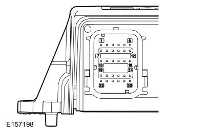
Refer to Wiring Diagrams Cell 46 for schematic and connector information. Normal Operation and Fault Conditions The RCM continuously monitors the driver airbag stage 1 circuits for the following faults:
If a fault is detected, the RCM stores DTC B0001:11, B0001:12, B0001:13 or B0001:1A in memory and sends a message to the IPC to illuminate the airbag warning indicator. The RCM analyzes the deployment loop resistance to determine if a fault exists. The value displayed in the PID is the deployment loop resistance measured by the RCM . If the value displayed is lower or higher than the desired range (refer to diagram below), the RCM can set a DTC . As the deployment loop resistance drifts farther outside the desired range, the chance for a DTC increases. Small variations in resistance can occur due to the effect of road vibrations on terminal fit. Crimps and terminals can be affected by stress and harness movement and can cause an increase in resistance due to wire strain. These variables can result in an intermittent fault. For this reason, the test requires the PID value to be within the desired range before the fault is considered repaired, regardless if the module is reporting an on-demand DTC at the time of diagnosis. Following this direction helps make sure that minor changes in resistance do not create a repeat concern. This test uses process of elimination to diagnose each part of the deployment loop circuit including:

DTC Fault Trigger Conditions
Possible Sources
NOTICE: Use the correct probe adapter(s) when making measurements. Failure to use the correct probe adapter(s) may cause damage to the connector. NOTE: Most faults are due to connector and/or wiring concerns. Carry out a thorough inspection and verification before proceeding with the pinpoint test. NOTE: Only disconnect or reconnect SRS components when instructed to do so within a pinpoint test step. Failure to follow this instruction may result in incorrect diagnosis of the SRS . NOTE: Always make sure the correct SRS component is being installed. Parts released for other vehicles may not be compatible even if they appear physically similar. Check the part number listed in the Ford parts catalog to make sure the correct component is being installed. If an incorrect SRS component is installed, Diagnostic Trouble Codes (DTCs) may set. NOTE: The SRS must be fully operational and free of faults before releasing the vehicle to the customer. |
|||||||||||||||
| A1 RETRIEVE RCM (RESTRAINTS CONTROL MODULE) DIAGNOSTIC TROUBLE CODES (DTCS) | |||||||||||||||
Was DTC B0001:11, B0001:12, B0001:13 or B0001:1A retrieved on-demand during self-test?
|
|||||||||||||||
| A2 CHECK THE DRIVER FRONTAL STAGE 1 DEPLOYMENT CONTROL RESISTANCE (DEPLOY_00_R) PID (PARAMETER IDENTIFICATION) | |||||||||||||||
Does the PID value read between 1.95 and 3.88 ohms?
|
|||||||||||||||
| A3 CHECK THE DRIVER FRONTAL STAGE 1 DEPLOYMENT CONTROL RESISTANCE (DEPLOY_00_R) PID (PARAMETER IDENTIFICATION) WHILE CARRYING OUT THE HARNESS TEST | |||||||||||||||
Does the PID value read between 1.95 and 3.88 ohms while carrying out the harness test?
|
|||||||||||||||
| A4 CHECK THE DRIVER FRONTAL STAGE 1 DEPLOYMENT CONTROL DTC (DIAGNOSTIC TROUBLE CODE) FOR A FAULT STATUS CHANGE (LOW RESISTANCE INDICATED) | |||||||||||||||
|
NOTE: This pinpoint test step attempts to change the fault reported by the RCM by inducing a different fault condition. If the reported fault changes, this indicates the RCM is functioning correctly and is not the source of the fault.
Did the on-demand DTC change from B0001:1A to B0001:13?
|
|||||||||||||||
| A5 CHECK THE DRIVER FRONTAL STAGE 1 DEPLOYMENT CONTROL DTC (DIAGNOSTIC TROUBLE CODE) FOR A FAULT STATUS CHANGE (LOW RESISTANCE INDICATED) (CLOCKSPRING DISCONNECTED) | |||||||||||||||
|
NOTE: This pinpoint test step attempts to change the fault reported by the RCM by inducing a different fault condition. If the reported fault changes, this indicates the RCM is functioning correctly and is not the source of the fault.
Did the on-demand DTC change from B0001:1A to B0001:13?
|
|||||||||||||||
| A6 CHECK FOR A SHORT BETWEEN DRIVER AIRBAG STAGE 1 CIRCUITS | |||||||||||||||
Is the resistance greater than 10,000 ohms?
|
|||||||||||||||
| A7 CHECK THE RCM (RESTRAINTS CONTROL MODULE) FOR LOW RESISTANCE | |||||||||||||||
Is the resistance greater than 10,000 ohms?
|
|||||||||||||||
| A8 CHECK THE DRIVER AIRBAG STAGE 1 CIRCUITS FOR AN OPEN | |||||||||||||||
Are the resistances less than 1 ohm?
|
|||||||||||||||
| A9 CHECK THE DRIVER AIRBAG STAGE 1 CIRCUITS FOR AN OPEN (CLOCKSPRING DISCONNECTED) | |||||||||||||||
Are the resistances less than 0.5 ohm?
|
|||||||||||||||
| A10 CHECK THE DRIVER AIRBAG STAGE 1 DEPLOYMENT CONTROL DTC (DIAGNOSTIC TROUBLE CODE) FOR A FAULT STATUS CHANGE (OPEN INDICATED) | |||||||||||||||
|
NOTE: This pinpoint test step attempts to change the fault reported by the RCM by inducing a different fault condition. If the reported fault changes, this indicates the RCM is functioning correctly and is not the source of the fault.
Was DTC B0001:1A retrieved on-demand during self-test?
|
|||||||||||||||
| A11 CHECK THE DRIVER AIRBAG STAGE 1 DEPLOYMENT CONTROL DTC (DIAGNOSTIC TROUBLE CODE) FOR A FAULT STATUS CHANGE (OPEN INDICATED) | |||||||||||||||
Was DTC B0001:1A retrieved on-demand during self-test?
|
|||||||||||||||
| A12 CHECK THE DRIVER FRONTAL STAGE 1 DEPLOYMENT CONTROL DTC (DIAGNOSTIC TROUBLE CODE) FOR A FAULT STATUS CHANGE (SHORT TO GROUND INDICATED) | |||||||||||||||
|
NOTE: This pinpoint test step attempts to change the fault reported by the RCM by inducing a different fault condition. If the reported fault changes, this indicates the RCM is functioning correctly and is not the source of the fault.
Did the on-demand DTC change from B0001:11 to B0001:13?
|
|||||||||||||||
| A13 CHECK THE DRIVER FRONTAL STAGE 1 DEPLOYMENT CONTROL DTC (DIAGNOSTIC TROUBLE CODE) FOR A FAULT STATUS CHANGE (SHORT TO GROUND INDICATED) (CLOCKSPRING DISCONNECTED) | |||||||||||||||
|
NOTE: This pinpoint test step attempts to change the fault reported by the RCM by inducing a different fault condition. If the reported fault changes, this indicates the RCM is functioning correctly and is not the source of the fault.
Did the on-demand DTC change from B0001:11 to B0001:13?
|
|||||||||||||||
| A14 CHECK THE DRIVER AIRBAG STAGE 1 CIRCUITS FOR A SHORT TO GROUND | |||||||||||||||
Are the resistances greater than 10,000 ohms?
|
|||||||||||||||
| A15 CHECK THE DRIVER FRONTAL STAGE 1 DEPLOYMENT CONTROL DTC (DIAGNOSTIC TROUBLE CODE) FOR A FAULT STATUS CHANGE (SHORT TO BATTERY INDICATED) (CLOCKSPRING DISCONNECTED) | |||||||||||||||
|
NOTE: This pinpoint test step attempts to change the fault reported by the RCM by inducing a different fault condition. If the reported fault changes, this indicates the RCM is functioning correctly and is not the source of the fault.
Did the on-demand DTC change from B0001:12 to B0001:13?
|
|||||||||||||||
| A16 CHECK THE DRIVER AIRBAG STAGE 1 CIRCUITS FOR A SHORT TO VOLTAGE | |||||||||||||||
Is any voltage present?
|
|||||||||||||||
| A17 CONFIRM THE DRIVER AIRBAG FAULT | |||||||||||||||
|
NOTE: Make sure all SRS components and the RCM electrical connectors are connected before carrying out the self-test. If not, Diagnostic Trouble Codes (DTCs) will be recorded.
Was the original DTC retrieved on-demand during self-test?
|
|||||||||||||||
| A18 CONFIRM THE CLOCKSPRING FAULT | |||||||||||||||
|
NOTE: Make sure all SRS components and the RCM electrical connectors are connected before carrying out the self-test. If not, Diagnostic Trouble Codes (DTCs) will be recorded.
Was the original DTC retrieved on-demand during self-test?
|
|||||||||||||||
| A19 CONFIRM THE RCM (RESTRAINTS CONTROL MODULE) FAULT | |||||||||||||||
|
NOTE: Make sure all SRS components and the RCM electrical connectors are connected before carrying out the self-test. If not, Diagnostic Trouble Codes (DTCs) will be recorded.
Was the original DTC retrieved on-demand during self-test?
|
|||||||||||||||
| A20 CHECK THE DRIVER FRONTAL STAGE 1 DEPLOYMENT CONTROL RESISTANCE (DEPLOY_00_R) PID (PARAMETER IDENTIFICATION) FOR AN INTERMITTENT LOW RESISTANCE OR OPEN CIRCUIT FAULT | |||||||||||||||
Does the PID value read between 1.95 and 3.88 ohms?
|
|||||||||||||||
| A21 CHECK THE DRIVER FRONTAL STAGE 1 DEPLOYMENT CONTROL CIRCUITS FOR AN INTERMITTENT SHORT TO GROUND FAULT | |||||||||||||||
Was DTC B0001:11 retrieved on-demand during self-test?
|
|||||||||||||||
| A22 CHECK THE DRIVER FRONTAL STAGE 1 DEPLOYMENT CONTROL CIRCUITS FOR AN INTERMITTENT SHORT TO BATTERY FAULT | |||||||||||||||
Was DTC B0001:12 retrieved on-demand during self-test?
|
|||||||||||||||
| A23 CHECK THE HARNESS AND CONNECTORS | |||||||||||||||
Were any concerns found?
|
|||||||||||||||
| A24 CHECK FOR ADDITIONAL SRS (SUPPLEMENTAL RESTRAINT SYSTEM) DIAGNOSTIC TROUBLE CODES (DTCS) | |||||||||||||||
Are any RCM Diagnostic Trouble Codes (DTCs) retrieved on-demand during self-test?
|
 WARNING:
Incorrect repair techniques or actions can cause an
accidental Supplemental Restraint System (SRS) deployment. Never
compromise or depart from these instructions. Failure to precisely
follow all instructions could result in serious personal injury from an
accidental deployment.
WARNING:
Incorrect repair techniques or actions can cause an
accidental Supplemental Restraint System (SRS) deployment. Never
compromise or depart from these instructions. Failure to precisely
follow all instructions could result in serious personal injury from an
accidental deployment.

 C310A, pin 29, component side


|
Refer to Wiring Diagrams Cell 46 for schematic and connector information. Normal Operation and Fault Conditions The RCM continuously monitors the driver airbag stage 2 circuits for the following faults:
If a fault is detected, the RCM stores DTC B0002:11, B0002:12, B0002:13 or B0002:1A in memory and sends a message to the IPC to illuminate the airbag warning indicator. The RCM analyzes the deployment loop resistance to determine if a fault exists. The value displayed in the PID is the deployment loop resistance measured by the RCM . If the value displayed is lower or higher than the desired range (refer to diagram below), the RCM can set a DTC . As the deployment loop resistance drifts farther outside the desired range, the chance for a DTC increases. Small variations in resistance can occur due to the effect of road vibrations on terminal fit. Crimps and terminals can be affected by stress and harness movement and can cause an increase in resistance due to wire strain. These variables can result in an intermittent fault. For this reason, the test requires the PID value to be within the desired range before the fault is considered repaired, regardless if the module is reporting an on-demand DTC at the time of diagnosis. Following this direction helps make sure that minor changes in resistance do not create a repeat concern. This test uses process of elimination to diagnose each part of the deployment loop circuit including:
DTC Fault Trigger Conditions
Possible Sources
Visual Inspection and Pre-checks
NOTICE: Use the correct probe adapter(s) when making measurements. Failure to use the correct probe adapter(s) may cause damage to the connector. NOTE: Most faults are due to connector and/or wiring concerns. Carry out a thorough inspection and verification before proceeding with the pinpoint test. NOTE: Only disconnect or reconnect SRS components when instructed to do so within a pinpoint test step. Failure to follow this instruction may result in incorrect diagnosis of the SRS . NOTE: Always make sure the correct SRS component is being installed. Parts released for other vehicles may not be compatible even if they appear physically similar. Check the part number listed in the Ford parts catalog to make sure the correct component is being installed. If an incorrect SRS component is installed, Diagnostic Trouble Codes (DTCs) may set. NOTE: The SRS must be fully operational and free of faults before releasing the vehicle to the customer. |
|||||||||||||||
| B1 RETRIEVE RCM (RESTRAINTS CONTROL MODULE) DIAGNOSTIC TROUBLE CODES (DTCS) | |||||||||||||||
Was DTC B0002:11, B0002:12, B0002:13 or B0002:1A retrieved on-demand during self-test?
|
|||||||||||||||
| B2 CHECK THE DRIVER FRONTAL STAGE 2 DEPLOYMENT CONTROL RESISTANCE (DEPLOY_01_R) PID (PARAMETER IDENTIFICATION) | |||||||||||||||
Does the PID value read between 1.95 and 3.88 ohms?
|
|||||||||||||||
| B3 CHECK THE DRIVER FRONTAL STAGE 2 DEPLOYMENT CONTROL RESISTANCE (DEPLOY_01_R) PID (PARAMETER IDENTIFICATION) WHILE CARRYING OUT THE HARNESS TEST | |||||||||||||||
Does the PID value read between 1.95 and 3.88 ohms while carrying out the harness test?
|
|||||||||||||||
| B4 CHECK THE DRIVER FRONTAL STAGE 2 DEPLOYMENT CONTROL DTC (DIAGNOSTIC TROUBLE CODE) FOR A FAULT STATUS CHANGE (LOW RESISTANCE INDICATED) | |||||||||||||||
|
NOTE: This pinpoint test step attempts to change the fault reported by the RCM by inducing a different fault condition. If the reported fault changes, this indicates the RCM is functioning correctly and is not the source of the fault.
Did the on-demand DTC change from B0002:1A to B0002:13?
|
|||||||||||||||
| B5 CHECK THE DRIVER FRONTAL STAGE 2 DEPLOYMENT CONTROL DTC (DIAGNOSTIC TROUBLE CODE) FOR A FAULT STATUS CHANGE (LOW RESISTANCE INDICATED) (CLOCKSPRING DISCONNECTED) | |||||||||||||||
|
NOTE: This pinpoint test step attempts to change the fault reported by the RCM by inducing a different fault condition. If the reported fault changes, this indicates the RCM is functioning correctly and is not the source of the fault.
Did the on-demand DTC change from B0002:1A to B0002:13?
|
|||||||||||||||
| B6 CHECK FOR A SHORT BETWEEN DRIVER AIRBAG STAGE 2 CIRCUITS | |||||||||||||||
Is the resistance greater than 10,000 ohms?
|
|||||||||||||||
| B7 CHECK THE DRIVER AIRBAG STAGE 2 CIRCUITS FOR AN OPEN | |||||||||||||||
Are the resistances less than 1 ohm?
|
|||||||||||||||
| B8 CHECK THE DRIVER AIRBAG STAGE 2 CIRCUITS FOR AN OPEN (CLOCKSPRING DISCONNECTED) | |||||||||||||||
Are the resistances less than 0.5 ohm?
|
|||||||||||||||
| B9 CHECK THE DRIVER AIRBAG STAGE 2 DEPLOYMENT CONTROL DTC (DIAGNOSTIC TROUBLE CODE) FOR A FAULT STATUS CHANGE (OPEN INDICATED) | |||||||||||||||
|
NOTE: This pinpoint test step attempts to change the fault reported by the RCM by inducing a different fault condition. If the reported fault changes, this indicates the RCM is functioning correctly and is not the source of the fault.
Was DTC B0002:1A retrieved on-demand during self-test?
|
|||||||||||||||
| B10 CHECK THE DRIVER AIRBAG STAGE 2 DEPLOYMENT CONTROL DTC (DIAGNOSTIC TROUBLE CODE) FOR A FAULT STATUS CHANGE (OPEN INDICATED) | |||||||||||||||
|
NOTE: This pinpoint test step attempts to change the fault reported by the RCM by inducing a different fault condition. If the reported fault changes, this indicates the RCM is functioning correctly and is not the source of the fault.
Was DTC B0002:1A retrieved on-demand during self-test?
|
|||||||||||||||
| B11 CHECK THE DRIVER FRONTAL STAGE 2 DEPLOYMENT CONTROL DTC (DIAGNOSTIC TROUBLE CODE) FOR A FAULT STATUS CHANGE (SHORT TO GROUND INDICATED) | |||||||||||||||
|
NOTE: This pinpoint test step attempts to change the fault reported by the RCM by inducing a different fault condition. If the reported fault changes, this indicates the RCM is functioning correctly and is not the source of the fault.
Did the on-demand DTC change from B0002:11 to B0002:13?
|
|||||||||||||||
| B12 CHECK THE DRIVER FRONTAL STAGE 2 DEPLOYMENT CONTROL DTC (DIAGNOSTIC TROUBLE CODE) FOR A FAULT STATUS CHANGE (SHORT TO GROUND INDICATED) (CLOCKSPRING DISCONNECTED) | |||||||||||||||
|
NOTE: This pinpoint test step attempts to change the fault reported by the RCM by inducing a different fault condition. If the reported fault changes, this indicates the RCM is functioning correctly and is not the source of the fault.
Did the on-demand DTC change from B0002:11 to B0002:13?
|
|||||||||||||||
| B13 CHECK THE DRIVER AIRBAG STAGE 2 CIRCUITS FOR A SHORT TO GROUND | |||||||||||||||
Are the resistances greater than 10,000 ohms?
|
|||||||||||||||
| B14 CHECK THE DRIVER FRONTAL STAGE 2 DEPLOYMENT CONTROL DTC (DIAGNOSTIC TROUBLE CODE) FOR A FAULT STATUS CHANGE (SHORT TO BATTERY INDICATED) (CLOCKSPRING DISCONNECTED) | |||||||||||||||
|
NOTE: This pinpoint test step attempts to change the fault reported by the RCM by inducing a different fault condition. If the reported fault changes, this indicates the RCM is functioning correctly and is not the source of the fault.
Did the on-demand DTC change from B0002:12 to B0002:13?
|
|||||||||||||||
| B15 CHECK THE DRIVER AIRBAG STAGE 2 CIRCUITS FOR A SHORT TO VOLTAGE | |||||||||||||||
Is any voltage present?
|
|||||||||||||||
| B16 CONFIRM THE DRIVER AIRBAG FAULT | |||||||||||||||
|
NOTE: Make sure all SRS components and the RCM electrical connectors are connected before carrying out the self-test. If not, Diagnostic Trouble Codes (DTCs) will be recorded.
Was the original DTC retrieved on-demand during self-test?
|
|||||||||||||||
| B17 CONFIRM THE CLOCKSPRING FAULT | |||||||||||||||
|
NOTE: Make sure all SRS components and the RCM electrical connectors are connected before carrying out the self-test. If not, Diagnostic Trouble Codes (DTCs) will be recorded.
Was the original DTC retrieved on-demand during self-test?
|
|||||||||||||||
| B18 CONFIRM THE RCM (RESTRAINTS CONTROL MODULE) FAULT | |||||||||||||||
|
NOTE: Make sure all SRS components and the RCM electrical connectors are connected before carrying out the self-test. If not, Diagnostic Trouble Codes (DTCs) will be recorded.
Was the original DTC retrieved on-demand during self-test?
|
|||||||||||||||
| B19 CHECK THE DRIVER FRONTAL STAGE 2 DEPLOYMENT CONTROL RESISTANCE (DEPLOY_01_R) PID (PARAMETER IDENTIFICATION) FOR AN INTERMITTENT LOW RESISTANCE OR OPEN CIRCUIT FAULT | |||||||||||||||
Does the PID value read between 1.95 and 3.88 ohms?
|
|||||||||||||||
| B20 CHECK THE DRIVER FRONTAL STAGE 2 DEPLOYMENT CONTROL CIRCUITS FOR AN INTERMITTENT SHORT TO GROUND FAULT | |||||||||||||||
Was DTC B0002:11 retrieved on-demand during self-test?
|
|||||||||||||||
| B21 CHECK THE DRIVER FRONTAL STAGE 2 DEPLOYMENT CONTROL CIRCUITS FOR AN INTERMITTENT SHORT TO BATTERY FAULT | |||||||||||||||
Was DTC B0002:12 retrieved on-demand during self-test?
|
|||||||||||||||
| B22 CHECK THE HARNESS AND CONNECTORS | |||||||||||||||
Were any concerns found?
|
|||||||||||||||
| B23 CHECK FOR ADDITIONAL SRS (SUPPLEMENTAL RESTRAINT SYSTEM) DIAGNOSTIC TROUBLE CODES (DTCS) | |||||||||||||||
Are any RCM or OCSM Diagnostic Trouble Codes (DTCs) retrieved on-demand during self-test?
|
|
Refer to Wiring Diagrams Cell 46 for schematic and connector information. Normal Operation and Fault Conditions The RCM continuously monitors the driver knee airbag circuits for the following faults:
If a fault is detected, the RCM stores DTC B0004:11, B0004:12, B0004:13 or B0004:1A in memory and sends a message to the IPC to illuminate the airbag warning indicator. The RCM analyzes the deployment loop resistance to determine if a fault exists. The value displayed in the PID is the deployment loop resistance measured by the RCM . If the value displayed is lower or higher than the desired range (refer to diagram below), the RCM can set a DTC . As the deployment loop resistance drifts farther outside the desired range, the chance for a DTC increases. Small variations in resistance can occur due to the effect of road vibrations on terminal fit. Crimps and terminals can be affected by stress and harness movement and can cause an increase in resistance due to wire strain. These variables can result in an intermittent fault. For this reason, the test requires the PID value to be within the desired range before the fault is considered repaired, regardless if the module is reporting an on-demand DTC at the time of diagnosis. Following this direction helps make sure that minor changes in resistance do not create a repeat concern. This test uses process of elimination to diagnose each part of the deployment loop circuit including:
DTC Fault Trigger Conditions
Possible Sources
NOTICE: Use the correct probe adapter(s) when making measurements. Failure to use the correct probe adapter(s) may cause damage to the connector. NOTE: Most faults are due to connector and/or wiring concerns. Carry out a thorough inspection and verification before proceeding with the pinpoint test. NOTE: Only disconnect or reconnect SRS components when instructed to do so within a pinpoint test step. Failure to follow this instruction may result in incorrect diagnosis of the SRS . NOTE: Always make sure the correct SRS component is being installed. Parts released for other vehicles may not be compatible even if they appear physically similar. Check the part number listed in the Ford parts catalog to make sure the correct component is being installed. If an incorrect SRS component is installed, Diagnostic Trouble Codes (DTCs) may set. NOTE: The SRS must be fully operational and free of faults before releasing the vehicle to the customer. |
|||||||||||||||
| C1 RETRIEVE RCM (RESTRAINTS CONTROL MODULE) DIAGNOSTIC TROUBLE CODES (DTCS) | |||||||||||||||
Was DTC B0004:11, B0004:12, B0004:13 and B0004:1A retrieved on-demand during self-test?
|
|||||||||||||||
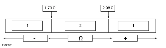
| C2 CHECK THE DRIVER KNEE BOLSTER DEPLOYMENT CONTROL (DEPLOY_02_R) PID (PARAMETER IDENTIFICATION) | |||||||||||||||
Does the PID value read between 1.7 and 2.98 ohms?
|
|||||||||||||||
| C3 CHECK THE DRIVER KNEE BOLSTER DEPLOYMENT CONTROL (DEPLOY_02_R) PID (PARAMETER IDENTIFICATION) WHILE CARRYING OUT THE HARNESS TEST | |||||||||||||||
Does the PID value read between 1.7 and 2.98 ohms while carrying out the harness test?
|
|||||||||||||||
| C4 CHECK THE DRIVER KNEE AIRBAG DEPLOYMENT CONTROL DTC (DIAGNOSTIC TROUBLE CODE) FOR A FAULT STATUS CHANGE (LOW RESISTANCE INDICATED) | |||||||||||||||
|
NOTE: This pinpoint test step attempts to change the fault reported by the RCM by inducing a different fault condition. If the reported fault changes, this indicates the RCM is functioning correctly and is not the source of the fault.
Did the on-demand DTC change from B0004:1A to B0004:13?
|
|||||||||||||||
| C5 CHECK FOR A SHORT BETWEEN THE DRIVER KNEE AIRBAG CIRCUITS | |||||||||||||||
Is the resistance greater than 10,000 ohms?
|
|||||||||||||||
| C6 CHECK THE DRIVER KNEE AIRBAG CIRCUITS FOR AN OPEN | |||||||||||||||
Are the resistances less than 0.5 ohm?
|
|||||||||||||||
| C7 CHECK THE DRIVER KNEE AIRBAG DEPLOYMENT CONTROL DTC (DIAGNOSTIC TROUBLE CODE) FOR A FAULT STATUS CHANGE (OPEN INDICATED) | |||||||||||||||
|
NOTE: This pinpoint test step attempts to change the fault reported by the RCM by inducing a different fault condition. If the reported fault changes, this indicates the RCM is functioning correctly and is not the source of the fault.
Did the on-demand DTC change from B0004:13 to B0004:1A?
|
|||||||||||||||
| C8 CHECK THE DRIVER KNEE AIRBAG DEPLOYMENT CONTROL DTC (DIAGNOSTIC TROUBLE CODE) FOR A FAULT STATUS CHANGE (SHORT TO GROUND INDICATED) | |||||||||||||||
|
NOTE: This pinpoint test step attempts to change the fault reported by the RCM by inducing a different fault condition. If the reported fault changes, this indicates the RCM is functioning correctly and is not the source of the fault.
Did the on-demand DTC change from B0004:11 to B0004:13?
|
|||||||||||||||
| C9 CHECK THE DRIVER KNEE AIRBAG CIRCUITS FOR A SHORT TO GROUND | |||||||||||||||
Are the resistances greater than 10,000 ohms?
|
|||||||||||||||
| C10 CHECK THE DRIVER KNEE AIRBAG CIRCUITS FOR A SHORT TO VOLTAGE | |||||||||||||||
Is any voltage present?
|
|||||||||||||||
| C11 CONFIRM THE DRIVER KNEE AIRBAG FAULT | |||||||||||||||
|
NOTE: Make sure all SRS components and the RCM electrical connectors are connected before carrying out the self-test. If not, Diagnostic Trouble Codes (DTCs) will be recorded.
Was the original DTC retrieved on-demand during self-test?
|
|||||||||||||||
| C12 CONFIRM THE RCM (RESTRAINTS CONTROL MODULE) FAULT | |||||||||||||||
|
NOTE: Make sure all SRS components and the RCM electrical connectors are connected before carrying out the self-test. If not, Diagnostic Trouble Codes (DTCs) will be recorded.
Was the original DTC retrieved on-demand during self-test?
|
|||||||||||||||
| C13 CHECK THE DRIVER KNEE BOLSTER DEPLOYMENT CONTROL (DEPLOY_02_R) PID (PARAMETER IDENTIFICATION) FOR AN INTERMITTENT LOW RESISTANCE OR OPEN CIRCUIT FAULT | |||||||||||||||
Does the PID value read between 1.7 and 2.98 ohms?
|
|||||||||||||||
| C14 CHECK THE DRIVER KNEE AIRBAG DEPLOYMENT CONTROL CIRCUITS FOR AN INTERMITTENT SHORT TO GROUND FAULT | |||||||||||||||
Was DTC B0004:11 retrieved on-demand during self-test?
|
|||||||||||||||
| C15 CHECK THE DRIVER KNEE AIRBAG DEPLOYMENT CONTROL CIRCUITS FOR AN INTERMITTENT SHORT TO BATTERY FAULT | |||||||||||||||
Was DTC B0004:12 retrieved on-demand during self-test?
|
|||||||||||||||
| C16 CHECK THE HARNESS AND CONNECTORS | |||||||||||||||
Were any concerns found?
|
|||||||||||||||
| C17 CHECK FOR ADDITIONAL SRS (SUPPLEMENTAL RESTRAINT SYSTEM) DIAGNOSTIC TROUBLE CODES (DTCS) | |||||||||||||||
Are any RCM or OCSM Diagnostic Trouble Codes (DTCs) retrieved on-demand during self-test?
|
|
Refer to Wiring Diagrams Cell 46 for schematic and connector information. Normal Operation and Fault Conditions The RCM continuously monitors the passenger airbag stage 1 circuits for the following faults:
If a fault is detected, the RCM stores DTC B0010:11, B0010:12, B0010:13 or B0010:1A in memory and sends a message to the IPC to illuminate the airbag warning indicator. The RCM analyzes the deployment loop resistance to determine if a fault exists. The value displayed in the PID is the deployment loop resistance measured by the RCM . If the value displayed is lower or higher than the desired range (refer to diagram below), the RCM can set a DTC . As the deployment loop resistance drifts farther outside the desired range, the chance for a DTC increases. Small variations in resistance can occur due to the effect of road vibrations on terminal fit. Crimps and terminals can be affected by stress and harness movement and can cause an increase in resistance due to wire strain. These variables can result in an intermittent fault. For this reason, the test requires the PID value to be within the desired range before the fault is considered repaired, regardless if the module is reporting an on-demand DTC at the time of diagnosis. Following this direction helps make sure that minor changes in resistance do not create a repeat concern. This test uses process of elimination to diagnose each part of the deployment loop circuit including:
DTC Fault Trigger Conditions
Possible Sources
Visual Inspection and Pre-checks
NOTICE: Use the correct probe adapter(s) when making measurements. Failure to use the correct probe adapter(s) may cause damage to the connector. NOTE: Most faults are due to connector and/or wiring concerns. Carry out a thorough inspection and verification before proceeding with the pinpoint test. NOTE: Only disconnect or reconnect SRS components when instructed to do so within a pinpoint test step. Failure to follow this instruction may result in incorrect diagnosis of the SRS . NOTE: Always make sure the correct SRS component is being installed. Parts released for other vehicles may not be compatible even if they appear physically similar. Check the part number listed in the Ford parts catalog to make sure the correct component is being installed. If an incorrect SRS component is installed, Diagnostic Trouble Codes (DTCs) may set. NOTE: The SRS must be fully operational and free of faults before releasing the vehicle to the customer. |
|||||||||||||||
| D1 RETRIEVE RCM (RESTRAINTS CONTROL MODULE) DIAGNOSTIC TROUBLE CODES (DTCS) | |||||||||||||||
Was DTC B0010:11, B0010:12, B0010:13 or B0010:1A retrieved on-demand during self-test?
|
|||||||||||||||
| D2 CHECK THE PASSENGER FRONTAL STAGE 1 DEPLOYMENT CONTROL RESISTANCE (DEPLOY_05_R) PID (PARAMETER IDENTIFICATION) | |||||||||||||||
Does the PID value read between 1.7 and 2.98 ohms?
|
|||||||||||||||
| D3 CHECK THE PASSENGER FRONTAL STAGE 1 DEPLOYMENT CONTROL RESISTANCE (DEPLOY_05_R) PID (PARAMETER IDENTIFICATION) WHILE CARRYING OUT THE HARNESS TEST | |||||||||||||||
Does the PID value read between 1.7 and 2.98 ohms while carrying out the harness test?
|
|||||||||||||||
| D4 CHECK THE PASSENGER FRONTAL STAGE 1 DEPLOYMENT CONTROL DTC (DIAGNOSTIC TROUBLE CODE) FOR A FAULT STATUS CHANGE (LOW RESISTANCE INDICATED) | |||||||||||||||
|
NOTE: This pinpoint test step attempts to change the fault reported by the RCM by inducing a different fault condition. If the reported fault changes, this indicates the RCM is functioning correctly and is not the source of the fault.
Did the on-demand DTC change from B0010:1A to B0010:13?
|
|||||||||||||||
| D5 CHECK FOR A SHORT BETWEEN PASSENGER AIRBAG STAGE 1 CIRCUITS | |||||||||||||||
Is the resistance greater than 10,000 ohms?
|
|||||||||||||||
| D6 CHECK THE RCM (RESTRAINTS CONTROL MODULE) FOR LOW RESISTANCE | |||||||||||||||
Is the resistance greater than 10,000 ohms?
|
|||||||||||||||
| D7 CHECK THE PASSENGER AIRBAG STAGE 1 CIRCUITS FOR AN OPEN | |||||||||||||||
Are the resistances less than 0.5 ohm?
|
|||||||||||||||
| D8 CHECK THE PASSENGER AIRBAG STAGE 1 DEPLOYMENT CONTROL DTC (DIAGNOSTIC TROUBLE CODE) FOR A FAULT STATUS CHANGE (OPEN INDICATED) | |||||||||||||||
|
NOTE: This pinpoint test step attempts to change the fault reported by the RCM by inducing a different fault condition. If the reported fault changes, this indicates the RCM is functioning correctly and is not the source of the fault.
Did the on-demand DTC change from B0010:13 to B0010:1A?
|
|||||||||||||||
| D9 CHECK THE PASSENGER FRONTAL STAGE 1 DEPLOYMENT CONTROL DTC (DIAGNOSTIC TROUBLE CODE) FOR A FAULT STATUS CHANGE (SHORT TO GROUND INDICATED) | |||||||||||||||
|
NOTE: This pinpoint test step attempts to change the fault reported by the RCM by inducing a different fault condition. If the reported fault changes, this indicates the RCM is functioning correctly and is not the source of the fault.
Did the on-demand DTC change from B0010:11 to B0010:13?
|
|||||||||||||||
| D10 CHECK THE PASSENGER AIRBAG STAGE 1 CIRCUITS FOR A SHORT TO GROUND | |||||||||||||||
Are the resistances greater than 10,000 ohms?
|
|||||||||||||||
| D11 CHECK THE PASSENGER AIRBAG STAGE 1 CIRCUITS FOR A SHORT TO VOLTAGE | |||||||||||||||
Is any voltage present?
|
|||||||||||||||
| D12 CONFIRM THE PASSENGER AIRBAG FAULT | |||||||||||||||
|
NOTE: Make sure all SRS components and the RCM electrical connectors are connected before carrying out the self-test. If not, Diagnostic Trouble Codes (DTCs) will be recorded.
Was the original DTC retrieved on-demand during self-test?
|
|||||||||||||||
| D13 CONFIRM THE RCM (RESTRAINTS CONTROL MODULE) FAULT | |||||||||||||||
|
NOTE: Make sure all SRS components and the RCM electrical connectors are connected before carrying out the self-test. If not, Diagnostic Trouble Codes (DTCs) will be recorded.
Was the original DTC retrieved on-demand during self-test?
|
|||||||||||||||
| D14 CHECK THE PASSENGER FRONTAL STAGE 1 DEPLOYMENT CONTROL RESISTANCE (DEPLOY_05_R) PID (PARAMETER IDENTIFICATION) FOR AN INTERMITTENT LOW RESISTANCE OR OPEN CIRCUIT FAULT | |||||||||||||||
Does the PID value read between 1.7 and 2.98 ohms?
|
|||||||||||||||
| D15 CHECK THE PASSENGER FRONTAL STAGE 1 DEPLOYMENT CONTROL CIRCUITS FOR AN INTERMITTENT SHORT TO GROUND FAULT | |||||||||||||||
Was DTC B0010:11 retrieved on-demand during self-test?
|
|||||||||||||||
| D16 CHECK THE PASSENGER FRONTAL STAGE 1 DEPLOYMENT CONTROL CIRCUITS FOR AN INTERMITTENT SHORT TO BATTERY FAULT | |||||||||||||||
Was DTC B0010:12 retrieved on-demand during self-test?
|
|||||||||||||||
| D17 CHECK THE HARNESS AND CONNECTORS | |||||||||||||||
Were any concerns found?
|
|||||||||||||||
| D18 CHECK FOR ADDITIONAL SRS (SUPPLEMENTAL RESTRAINT SYSTEM) DIAGNOSTIC TROUBLE CODES (DTCS) | |||||||||||||||
Are any RCM or OCSM Diagnostic Trouble Codes (DTCs) retrieved on-demand during self-test?
|
|
Refer to Wiring Diagrams Cell 46 for schematic and connector information. Normal Operation and Fault Conditions The RCM continuously monitors the passenger airbag stage 2 circuits for the following faults:
If a fault is detected, the RCM stores DTC B0011:11, B0011:12, B0011:13 or B0011:1A in memory and sends a message to the IPC to illuminate the airbag warning indicator. The RCM analyzes the deployment loop resistance to determine if a fault exists. The value displayed in the PID is the deployment loop resistance measured by the RCM . If the value displayed is lower or higher than the desired range (refer to diagram below), the RCM can set a DTC . As the deployment loop resistance drifts farther outside the desired range, the chance for a DTC increases. Small variations in resistance can occur due to the effect of road vibrations on terminal fit. Crimps and terminals can be affected by stress and harness movement and can cause an increase in resistance due to wire strain. These variables can result in an intermittent fault. For this reason, the test requires the PID value to be within the desired range before the fault is considered repaired, regardless if the module is reporting an on-demand DTC at the time of diagnosis. Following this direction helps make sure that minor changes in resistance do not create a repeat concern. This test uses process of elimination to diagnose each part of the deployment loop circuit including:
DTC Fault Trigger Conditions
Possible Sources
Visual Inspection and Pre-checks
NOTICE: Use the correct probe adapter(s) when making measurements. Failure to use the correct probe adapter(s) may cause damage to the connector. NOTE: Most faults are due to connector and/or wiring concerns. Carry out a thorough inspection and verification before proceeding with the pinpoint test. NOTE: Only disconnect or reconnect SRS components when instructed to do so within a pinpoint test step. Failure to follow this instruction may result in incorrect diagnosis of the SRS . NOTE: Always make sure the correct SRS component is being installed. Parts released for other vehicles may not be compatible even if they appear physically similar. Check the part number listed in the Ford parts catalog to make sure the correct component is being installed. If an incorrect SRS component is installed, Diagnostic Trouble Codes (DTCs) may set. NOTE: The SRS must be fully operational and free of faults before releasing the vehicle to the customer. |
|||||||||||||||
| E1 RETRIEVE RCM (RESTRAINTS CONTROL MODULE) DIAGNOSTIC TROUBLE CODES (DTCS) | |||||||||||||||
Was DTC B0011:11, B0011:12, B0011:13 and B0011:1A retrieved on-demand during self-test?
|
|||||||||||||||
| E2 CHECK THE PASSENGER FRONTAL STAGE 2 DEPLOYMENT CONTROL RESISTANCE (DEPLOY_06_R) PID (PARAMETER IDENTIFICATION) | |||||||||||||||
Does the PID value read between 1.7 and 2.98 ohms?
|
|||||||||||||||
| E3 CHECK THE PASSENGER FRONTAL STAGE 2 DEPLOYMENT CONTROL RESISTANCE (DEPLOY_06_R) PID (PARAMETER IDENTIFICATION) WHILE CARRYING OUT THE HARNESS TEST | |||||||||||||||
Does the PID value read between 1.7 and 2.98 ohms while carrying out the harness test?
|
|||||||||||||||
| E4 CHECK THE PASSENGER AIRBAG DEPLOYMENT CONTROL DTC (DIAGNOSTIC TROUBLE CODE) FOR A FAULT STATUS CHANGE (LOW RESISTANCE INDICATED) | |||||||||||||||
|
NOTE: This pinpoint test step attempts to change the fault reported by the RCM by inducing a different fault condition. If the reported fault changes, this indicates the RCM is functioning correctly and is not the source of the fault.
Did the on-demand DTC change from B0011:1A to B0011:13?
|
|||||||||||||||
| E5 CHECK FOR A SHORT BETWEEN THE PASSENGER AIRBAG CIRCUITS | |||||||||||||||
Is the resistance greater than 10,000 ohms?
|
|||||||||||||||
| E6 CHECK THE PASSENGER AIRBAG CIRCUITS FOR AN OPEN | |||||||||||||||
Are the resistances less than 0.5 ohm?
|
|||||||||||||||
| E7 CHECK THE PASSENGER AIRBAG DEPLOYMENT CONTROL DTC (DIAGNOSTIC TROUBLE CODE) FOR A FAULT STATUS CHANGE (OPEN INDICATED) | |||||||||||||||
|
NOTE: This pinpoint test step attempts to change the fault reported by the RCM by inducing a different fault condition. If the reported fault changes, this indicates the RCM is functioning correctly and is not the source of the fault.
Did the on-demand DTC change from B0011:13 to B0011:1A?
|
|||||||||||||||
| E8 CHECK THE PASSENGER AIRBAG DEPLOYMENT CONTROL DTC (DIAGNOSTIC TROUBLE CODE) FOR A FAULT STATUS CHANGE (SHORT TO GROUND INDICATED) | |||||||||||||||
|
NOTE: This pinpoint test step attempts to change the fault reported by the RCM by inducing a different fault condition. If the reported fault changes, this indicates the RCM is functioning correctly and is not the source of the fault.
Did the on-demand DTC change from B0011:11 to B0011:13?
|
|||||||||||||||
| E9 CHECK THE PASSENGER AIRBAG CIRCUITS FOR A SHORT TO GROUND | |||||||||||||||
Are the resistances greater than 10,000 ohms?
|
|||||||||||||||
| E10 CHECK THE PASSENGER AIRBAG CIRCUITS FOR A SHORT TO VOLTAGE | |||||||||||||||
Is any voltage present?
|
|||||||||||||||
| E11 CONFIRM THE PASSENGER AIRBAG FAULT | |||||||||||||||
|
NOTE: Make sure all SRS components and the RCM electrical connectors are connected before carrying out the self-test. If not, Diagnostic Trouble Codes (DTCs) will be recorded.
Was the original DTC retrieved on-demand during self-test?
|
|||||||||||||||
| E12 CONFIRM THE RCM (RESTRAINTS CONTROL MODULE) FAULT | |||||||||||||||
|
NOTE: Make sure all SRS components and the RCM electrical connectors are connected before carrying out the self-test. If not, Diagnostic Trouble Codes (DTCs) will be recorded.
Was the original DTC retrieved on-demand during self-test?
|
|||||||||||||||
| E13 CHECK THE PASSENGER FRONTAL STAGE 2 DEPLOYMENT CONTROL RESISTANCE (DEPLOY_06_R) PID (PARAMETER IDENTIFICATION) FOR AN INTERMITTENT LOW RESISTANCE OR OPEN CIRCUIT FAULT | |||||||||||||||
Does the PID value read between 1.7 and 2.98 ohms?
|
|||||||||||||||
| E14 CHECK THE PASSENGER AIRBAG DEPLOYMENT CONTROL CIRCUITS FOR AN INTERMITTENT SHORT TO GROUND FAULT | |||||||||||||||
Was DTC B0011:11 retrieved on-demand during self-test?
|
|||||||||||||||
| E15 CHECK THE PASSENGER AIRBAG DEPLOYMENT CONTROL CIRCUITS FOR AN INTERMITTENT SHORT TO BATTERY FAULT | |||||||||||||||
Was DTC B0011:12 retrieved on-demand during self-test?
|
|||||||||||||||
| E16 CHECK THE HARNESS AND CONNECTORS | |||||||||||||||
Were any concerns found?
|
|||||||||||||||
| E17 CHECK FOR ADDITIONAL SRS (SUPPLEMENTAL RESTRAINT SYSTEM) DIAGNOSTIC TROUBLE CODES (DTCS) | |||||||||||||||
Are any RCM or OCSM Diagnostic Trouble Codes (DTCs) retrieved on-demand during self-test?
|
|
Refer to Wiring Diagrams Cell 46 for schematic and connector information. Normal Operation and Fault Conditions The RCM continuously monitors the passenger knee airbag circuits for the following faults:
If a fault is detected, the RCM stores DTC B0013:11, B0013:12, B0013:13 or B0013:1A in memory and sends a message to the IPC to illuminate the airbag warning indicator. The RCM analyzes the deployment loop resistance to determine if a fault exists. The value displayed in the PID is the deployment loop resistance measured by the RCM . If the value displayed is lower or higher than the desired range (refer to diagram below), the RCM can set a DTC . As the deployment loop resistance drifts farther outside the desired range, the chance for a DTC increases. Small variations in resistance can occur due to the effect of road vibrations on terminal fit. Crimps and terminals can be affected by stress and harness movement and can cause an increase in resistance due to wire strain. These variables can result in an intermittent fault. For this reason, the test requires the PID value to be within the desired range before the fault is considered repaired, regardless if the module is reporting an on-demand DTC at the time of diagnosis. Following this direction helps make sure that minor changes in resistance do not create a repeat concern. This test uses process of elimination to diagnose each part of the deployment loop circuit including:
DTC Fault Trigger Conditions
Possible Sources
Visual Inspection and Pre-checks
NOTICE: Use the correct probe adapter(s) when making measurements. Failure to use the correct probe adapter(s) may cause damage to the connector. NOTE: Most faults are due to connector and/or wiring concerns. Carry out a thorough inspection and verification before proceeding with the pinpoint test. NOTE: Only disconnect or reconnect SRS components when instructed to do so within a pinpoint test step. Failure to follow this instruction may result in incorrect diagnosis of the SRS . NOTE: Always make sure the correct SRS component is being installed. Parts released for other vehicles may not be compatible even if they appear physically similar. Check the part number listed in the Ford parts catalog to make sure the correct component is being installed. If an incorrect SRS component is installed, Diagnostic Trouble Codes (DTCs) may set. NOTE: The SRS must be fully operational and free of faults before releasing the vehicle to the customer. |
|||||||||||||||
| F1 RETRIEVE RCM (RESTRAINTS CONTROL MODULE) DIAGNOSTIC TROUBLE CODES (DTCS) | |||||||||||||||
Was DTC B0013:11, B0013:12, B0013:13 and B0013:1A retrieved on-demand during self-test?
|
|||||||||||||||
| F2 CHECK THE PASSENGER KNEE BOLSTER DEPLOYMENT CONTROL (DEPLOY_07_R) PID (PARAMETER IDENTIFICATION) | |||||||||||||||
Does the PID value read between 1.7 and 2.98 ohms?
|
|||||||||||||||
| F3 CHECK THE PASSENGER KNEE BOLSTER DEPLOYMENT CONTROL (DEPLOY_07_R) PID (PARAMETER IDENTIFICATION) WHILE CARRYING OUT THE HARNESS TEST | |||||||||||||||
Does the PID value read between 1.7 and 2.98 ohms while carrying out the harness test?
|
|||||||||||||||
| F4 CHECK THE PASSENGER KNEE AIRBAG DEPLOYMENT CONTROL DTC (DIAGNOSTIC TROUBLE CODE) FOR A FAULT STATUS CHANGE (LOW RESISTANCE INDICATED) | |||||||||||||||
|
NOTE: This pinpoint test step attempts to change the fault reported by the RCM by inducing a different fault condition. If the reported fault changes, this indicates the RCM is functioning correctly and is not the source of the fault.
Did the on-demand DTC change from B0013:1A to B0013:13?
|
|||||||||||||||
| F5 CHECK FOR A SHORT BETWEEN THE PASSENGER KNEE AIRBAG CIRCUITS | |||||||||||||||
Is the resistance greater than 10,000 ohms?
|
|||||||||||||||
| F6 CHECK THE PASSENGER KNEE AIRBAG CIRCUITS FOR AN OPEN | |||||||||||||||
Are the resistances less than 0.5 ohm?
|
|||||||||||||||
| F7 CHECK THE PASSENGER KNEE AIRBAG DEPLOYMENT CONTROL DTC (DIAGNOSTIC TROUBLE CODE) FOR A FAULT STATUS CHANGE (OPEN INDICATED) | |||||||||||||||
|
NOTE: This pinpoint test step attempts to change the fault reported by the RCM by inducing a different fault condition. If the reported fault changes, this indicates the RCM is functioning correctly and is not the source of the fault.
Did the on-demand DTC change from B0013:13 to B0013:1A?
|
|||||||||||||||
| F8 CHECK THE PASSENGER KNEE AIRBAG DEPLOYMENT CONTROL DTC (DIAGNOSTIC TROUBLE CODE) FOR A FAULT STATUS CHANGE (SHORT TO GROUND INDICATED) | |||||||||||||||
|
NOTE: This pinpoint test step attempts to change the fault reported by the RCM by inducing a different fault condition. If the reported fault changes, this indicates the RCM is functioning correctly and is not the source of the fault.
Did the on-demand DTC change from B0013:11 to B0013:13?
|
|||||||||||||||
| F9 CHECK THE PASSENGER KNEE AIRBAG CIRCUITS FOR A SHORT TO GROUND | |||||||||||||||
Are the resistances greater than 10,000 ohms?
|
|||||||||||||||
| F10 CHECK THE PASSENGER KNEE AIRBAG CIRCUITS FOR A SHORT TO VOLTAGE | |||||||||||||||
Is any voltage present?
|
|||||||||||||||
| F11 CONFIRM THE PASSENGER KNEE AIRBAG FAULT | |||||||||||||||
|
NOTE: Make sure all SRS components and the RCM electrical connectors are connected before carrying out the self-test. If not, Diagnostic Trouble Codes (DTCs) will be recorded.
Was the original DTC retrieved on-demand during self-test?
|
|||||||||||||||
| F12 CONFIRM THE RCM (RESTRAINTS CONTROL MODULE) FAULT | |||||||||||||||
|
NOTE: Make sure all SRS components and the RCM electrical connectors are connected before carrying out the self-test. If not, Diagnostic Trouble Codes (DTCs) will be recorded.
Was the original DTC retrieved on-demand during self-test?
|
|||||||||||||||
| F13 CHECK THE PASSENGER KNEE BOLSTER DEPLOYMENT CONTROL (DEPLOY_07_R) PID (PARAMETER IDENTIFICATION) FOR AN INTERMITTENT LOW RESISTANCE OR OPEN CIRCUIT FAULT | |||||||||||||||
Does the PID value read between 1.7 and 2.98 ohms?
|
|||||||||||||||
| F14 CHECK THE PASSENGER KNEE AIRBAG DEPLOYMENT CONTROL CIRCUITS FOR AN INTERMITTENT SHORT TO GROUND FAULT | |||||||||||||||
Was DTC B0013:11 retrieved on-demand during self-test?
|
|||||||||||||||
| F15 CHECK THE PASSENGER KNEE AIRBAG DEPLOYMENT CONTROL CIRCUITS FOR AN INTERMITTENT SHORT TO BATTERY FAULT | |||||||||||||||
Was DTC B0013:12 retrieved on-demand during self-test?
|
|||||||||||||||
| F16 CHECK THE HARNESS AND CONNECTORS | |||||||||||||||
Were any concerns found?
|
|||||||||||||||
| F17 CHECK FOR ADDITIONAL SRS (SUPPLEMENTAL RESTRAINT SYSTEM) DIAGNOSTIC TROUBLE CODES (DTCS) | |||||||||||||||
Are any RCM or OCSM Diagnostic Trouble Codes (DTCs) retrieved on-demand during self-test?
|
|
Refer to Wiring Diagrams Cell 46 for schematic and connector information. Normal Operation and Fault Conditions The RCM monitors the driver seatbelt buckle switch circuits for the following faults:
If a fault is detected, the RCM stores DTC B0050:11, B0050:12, B0050:13 or B0050:1D in memory and sends a message to the IPC to illuminate the airbag warning indicator. DTC Fault Trigger Conditions
Possible Sources
NOTICE: Use the correct probe adapter(s) when making measurements. Failure to use the correct probe adapter(s) may cause damage to the connector. NOTE: Most faults are due to connector and/or wiring concerns. Carry out a thorough inspection and verification before proceeding with the pinpoint test. NOTE: Only disconnect or reconnect SRS components when instructed to do so within a pinpoint test step. Failure to follow this instruction may result in incorrect diagnosis of the SRS . NOTE: Always make sure the correct SRS component is being installed. Parts released for other vehicles may not be compatible even if they appear physically similar. Check the part number listed in the Ford parts catalog to make sure the correct component is being installed. If an incorrect SRS component is installed, Diagnostic Trouble Codes (DTCs) may set. NOTE: The SRS must be fully operational and free of faults before releasing the vehicle to the customer. |
|||||||||||||||
| G1 RETRIEVE RCM (RESTRAINTS CONTROL MODULE) DIAGNOSTIC TROUBLE CODES (DTCS) | |||||||||||||||
Was DTC B0050:11, B0050:12, B0050:13 or B0050:1D retrieved on-demand during self-test?
|
|||||||||||||||
| G2 CHECK THE DRIVER SEATBELT SENSOR DTC (DIAGNOSTIC TROUBLE CODE) FOR A FAULT STATUS CHANGE (SHORT TO GROUND OR CURRENT OUT OF RANGE INDICATED) | |||||||||||||||
|
NOTE: This pinpoint test step attempts to change the fault reported by the RCM by inducing a different fault condition. If the reported fault changes, this indicates the RCM is functioning correctly and is not the source of the fault.
Did the on-demand DTC change from B0050:11 or B0050:1D to B0050:13?
|
|||||||||||||||
| G3 CHECK THE DRIVER SEATBELT BUCKLE SWITCH CIRCUIT FOR A SHORT TO GROUND | |||||||||||||||
Is the resistance greater than 10,000 ohms?
|
|||||||||||||||
| G4 CHECK THE DRIVER SEATBELT BUCKLE SWITCH CIRCUIT FOR A SHORT TO VOLTAGE | |||||||||||||||
Is any voltage present?
|
|||||||||||||||
| G5 CHECK THE DRIVER SEATBELT SENSOR DTC (DIAGNOSTIC TROUBLE CODE) FOR A FAULT STATUS CHANGE (OPEN INDICATED) | |||||||||||||||
|
NOTE: This pinpoint test step attempts to change the fault reported by the RCM by inducing a different fault condition. If the reported fault changes, this indicates the RCM is functioning correctly and is not the source of the fault.
Did the on-demand DTC change from B0050:13 to B0050:11?
|
|||||||||||||||
| G6 CHECK THE DRIVER SEATBELT BUCKLE SWITCH CIRCUIT FOR AN OPEN | |||||||||||||||
Is the resistance less than 0.5 ohm?
|
|||||||||||||||
| G7 CHECK THE DRIVER SEATBELT BUCKLE SWITCH GROUND CIRCUIT FOR AN OPEN | |||||||||||||||
Is the resistance less than 3 ohms?
|
|||||||||||||||
| G8 CONFIRM THE DRIVER SEATBELT BUCKLE SWITCH FAULT | |||||||||||||||
|
NOTE: Make sure all SRS components and the RCM electrical connectors are connected before carrying out the self-test. If not, Diagnostic Trouble Codes (DTCs) will be recorded.
Was the original DTC retrieved on-demand during self-test?
|
|||||||||||||||
| G9 CONFIRM THE RCM (RESTRAINTS CONTROL MODULE) FAULT | |||||||||||||||
|
NOTE: Make sure all SRS components and the RCM electrical connectors are connected before carrying out the self-test. If not, Diagnostic Trouble Codes (DTCs) will be recorded.
Was the original DTC retrieved on-demand during self-test?
|
|||||||||||||||
| G10 CHECK FOR AN INTERMITTENT FAULT | |||||||||||||||
Was DTC B0050:11, B0050:12, B0050:13 or B0050:1D retrieved on-demand during self-test?
|
|||||||||||||||
| G11 CHECK FOR ADDITIONAL SRS (SUPPLEMENTAL RESTRAINT SYSTEM) DIAGNOSTIC TROUBLE CODES (DTCS) | |||||||||||||||
Are any RCM or OCSM Diagnostic Trouble Codes (DTCs) retrieved on-demand during self-test?
|
|
Refer to Wiring Diagrams Cell 46 for schematic and connector information. Normal Operation and Fault Conditions The RCM monitors the passenger seatbelt buckle switch circuits for the following faults:
If a fault is detected, the RCM stores DTC B0052:11, B0052:12, B0052:13 or B0052:1D in memory and sends a message to the IPC to illuminate the airbag warning indicator. DTC Fault Trigger Conditions
Possible Sources
NOTICE: Use the correct probe adapter(s) when making measurements. Failure to use the correct probe adapter(s) may cause damage to the connector. NOTE: Most faults are due to connector and/or wiring concerns. Carry out a thorough inspection and verification before proceeding with the pinpoint test. NOTE: Only disconnect or reconnect SRS components when instructed to do so within a pinpoint test step. Failure to follow this instruction may result in incorrect diagnosis of the SRS . NOTE: Always make sure the correct SRS component is being installed. Parts released for other vehicles may not be compatible even if they appear physically similar. Check the part number listed in the Ford parts catalog to make sure the correct component is being installed. If an incorrect SRS component is installed, Diagnostic Trouble Codes (DTCs) may set. NOTE: The SRS must be fully operational and free of faults before releasing the vehicle to the customer. |
|||||||||||||||
| H1 RETRIEVE RCM (RESTRAINTS CONTROL MODULE) DIAGNOSTIC TROUBLE CODES (DTCS) | |||||||||||||||
Was DTC B0052:11, B0052:12, B0052:13 or B0052:1D retrieved on-demand during self-test?
|
|||||||||||||||
| H2 CHECK THE PASSENGER SEATBELT SENSOR DTC (DIAGNOSTIC TROUBLE CODE) FOR A FAULT STATUS CHANGE (SHORT TO GROUND OR CURRENT OUT OF RANGE INDICATED) | |||||||||||||||
|
NOTE: This pinpoint test step attempts to change the fault reported by the RCM by inducing a different fault condition. If the reported fault changes, this indicates the RCM is functioning correctly and is not the source of the fault.
Did the on-demand DTC change from B0052:11 or B0052:1D to B0052:13?
|
|||||||||||||||
| H3 CHECK THE PASSENGER SEATBELT BUCKLE SWITCH CIRCUIT FOR A SHORT TO GROUND | |||||||||||||||
Is the resistance greater than 10,000 ohms?
|
|||||||||||||||
| H4 CHECK THE PASSENGER SEATBELT BUCKLE SWITCH CIRCUIT FOR A SHORT TO VOLTAGE | |||||||||||||||
Is any voltage present?
|
|||||||||||||||
| H5 CHECK THE PASSENGER SEATBELT SENSOR DTC (DIAGNOSTIC TROUBLE CODE) FOR A FAULT STATUS CHANGE (OPEN INDICATED) | |||||||||||||||
|
NOTE: This pinpoint test step attempts to change the fault reported by the RCM by inducing a different fault condition. If the reported fault changes, this indicates the RCM is functioning correctly and is not the source of the fault.
Did the on-demand DTC change from B0052:13 to B0052:11?
|
|||||||||||||||
| H6 CHECK THE PASSENGER SEATBELT BUCKLE SWITCH CIRCUIT FOR AN OPEN | |||||||||||||||
Is the resistance less than 0.5 ohm?
|
|||||||||||||||
| H7 CHECK THE PASSENGER SEATBELT BUCKLE SWITCH GROUND CIRCUIT FOR AN OPEN | |||||||||||||||
Is the resistance less than 3 ohms?
|
|||||||||||||||
| H8 CONFIRM THE PASSENGER SEATBELT BUCKLE SWITCH FAULT | |||||||||||||||
|
NOTE: Make sure all SRS components and the RCM electrical connectors are connected before carrying out the self-test. If not, Diagnostic Trouble Codes (DTCs) will be recorded.
Was the original DTC retrieved on-demand during self-test?
|
|||||||||||||||
| H9 CONFIRM THE RCM (RESTRAINTS CONTROL MODULE) FAULT | |||||||||||||||
|
NOTE: Make sure all SRS components and the RCM electrical connectors are connected before carrying out the self-test. If not, Diagnostic Trouble Codes (DTCs) will be recorded.
Was the original DTC retrieved on-demand during self-test?
|
|||||||||||||||
| H10 CHECK FOR AN INTERMITTENT FAULT | |||||||||||||||
Was DTC B0052:11, B0052:12, B0052:13 or B0052:1D retrieved on-demand during self-test?
|
|||||||||||||||
| H11 CHECK FOR ADDITIONAL SRS (SUPPLEMENTAL RESTRAINT SYSTEM) DIAGNOSTIC TROUBLE CODES (DTCS) | |||||||||||||||
Are any RCM or OCSM Diagnostic Trouble Codes (DTCs) retrieved on-demand during self-test?
|
|
Refer to Wiring Diagrams Cell 46 for schematic and connector information. Normal Operation and Fault Conditions The RCM continuously monitors the driver Seatbelt anchor pretensioner circuits for the following faults:
If a fault is detected, the RCM stores DTC B0070:11, B0070:12, B0070:13 or B0070:1A in memory and sends a message to the IPC to illuminate the airbag warning indicator. The RCM analyzes the deployment loop resistance to determine if a fault exists. The value displayed in the PID is the deployment loop resistance measured by the RCM . If the value displayed is lower or higher than the desired range (refer to diagram below), the RCM can set a DTC . As the deployment loop resistance drifts farther outside the desired range, the chance for a DTC increases. Small variations in resistance can occur due to the effect of road vibrations on terminal fit. Crimps and terminals can be affected by stress and harness movement and can cause an increase in resistance due to wire strain. These variables can result in an intermittent fault. For this reason, the test requires the PID value to be within the desired range before the fault is considered repaired, regardless if the module is reporting an on-demand DTC at the time of diagnosis. Following this direction helps make sure that minor changes in resistance do not create a repeat concern. This test uses process of elimination to diagnose each part of the deployment loop circuit including:
DTC Fault Trigger Conditions
Possible Sources
NOTICE: Use the correct probe adapter(s) when making measurements. Failure to use the correct probe adapter(s) may cause damage to the connector. NOTE: Most faults are due to connector and/or wiring concerns. Carry out a thorough inspection and verification before proceeding with the pinpoint test. NOTE: Only disconnect or reconnect SRS components when instructed to do so within a pinpoint test step. Failure to follow this instruction may result in incorrect diagnosis of the SRS . NOTE: Always make sure the correct SRS component is being installed. Parts released for other vehicles may not be compatible even if they appear physically similar. Check the part number listed in the Ford parts catalog to make sure the correct component is being installed. If an incorrect SRS component is installed, Diagnostic Trouble Codes (DTCs) may set. NOTE: The SRS must be fully operational and free of faults before releasing the vehicle to the customer. |
|||||||||||||||
| I1 RETRIEVE RCM (RESTRAINTS CONTROL MODULE) DIAGNOSTIC TROUBLE CODES (DTCS) | |||||||||||||||
Was DTC B0070:11, B0070:12, B0070:13 and B0070:1A retrieved on-demand during self-test?
|
|||||||||||||||
| I2 CHECK THE DRIVER SEATBELT ANCHOR PRETENSIONER DEPLOYMENT CONTROL (DEPLOY_29_RES) PID (PARAMETER IDENTIFICATION) | |||||||||||||||
Does the PID value read between 1.7 and 2.98 ohms?
|
|||||||||||||||
| I3 CHECK THE DRIVER SEATBELT ANCHOR PRETENSIONER DEPLOYMENT CONTROL (DEPLOY_29_R) PID (PARAMETER IDENTIFICATION) WHILE CARRYING OUT THE HARNESS TEST | |||||||||||||||
Does the PID value read between 1.7 and 2.98 ohms while carrying out the harness test?
|
|||||||||||||||
| I4 CHECK THE DRIVER SEATBELT ANCHOR PRETENSIONER DEPLOYMENT CONTROL DTC (DIAGNOSTIC TROUBLE CODE) FOR A FAULT STATUS CHANGE (LOW RESISTANCE INDICATED) | |||||||||||||||
|
NOTE: This pinpoint test step attempts to change the fault reported by the RCM by inducing a different fault condition. If the reported fault changes, this indicates the RCM is functioning correctly and is not the source of the fault.
Did the on-demand DTC change from B0070:1A to B0070:13?
|
|||||||||||||||
| I5 CHECK FOR A SHORT BETWEEN THE DRIVER SEATBELT ANCHOR PRETENSIONER CIRCUITS | |||||||||||||||
Is the resistance greater than 10,000 ohms?
|
|||||||||||||||
| I6 CHECK THE DRIVER SEATBELT ANCHOR PRETENSIONER CIRCUITS FOR AN OPEN | |||||||||||||||
Are the resistances less than 0.5 ohm?
|
|||||||||||||||
| I7 CHECK THE DRIVER SEATBELT ANCHOR PRETENSIONER DEPLOYMENT CONTROL DTC (DIAGNOSTIC TROUBLE CODE) FOR A FAULT STATUS CHANGE (OPEN INDICATED) | |||||||||||||||
|
NOTE: This pinpoint test step attempts to change the fault reported by the RCM by inducing a different fault condition. If the reported fault changes, this indicates the RCM is functioning correctly and is not the source of the fault.
Did the on-demand DTC change from B0070:13 to B0070:1A?
|
|||||||||||||||
| I8 CHECK THE DRIVER SEATBELT ANCHOR PRETENSIONER DEPLOYMENT CONTROL DTC (DIAGNOSTIC TROUBLE CODE) FOR A FAULT STATUS CHANGE (SHORT TO GROUND INDICATED) | |||||||||||||||
|
NOTE: This pinpoint test step attempts to change the fault reported by the RCM by inducing a different fault condition. If the reported fault changes, this indicates the RCM is functioning correctly and is not the source of the fault.
Did the on-demand DTC change from B0070:11 to B0070:13?
|
|||||||||||||||
| I9 CHECK THE DRIVER SEATBELT ANCHOR PRETENSIONER CIRCUITS FOR A SHORT TO GROUND | |||||||||||||||
Are the resistances greater than 10,000 ohms?
|
|||||||||||||||
| I10 CHECK THE DRIVER SEATBELT ANCHOR PRETENSIONER CIRCUITS FOR A SHORT TO VOLTAGE | |||||||||||||||
Is any voltage present?
|
|||||||||||||||
| I11 CONFIRM THE DRIVER SEATBELT ANCHOR PRETENSIONER FAULT | |||||||||||||||
|
NOTE: Make sure all SRS components and the RCM electrical connectors are connected before carrying out the self-test. If not, Diagnostic Trouble Codes (DTCs) will be recorded.
Was the original DTC retrieved on-demand during self-test?
|
|||||||||||||||
| I12 CONFIRM THE RCM (RESTRAINTS CONTROL MODULE) FAULT | |||||||||||||||
|
NOTE: Make sure all SRS components and the RCM electrical connectors are connected before carrying out the self-test. If not, Diagnostic Trouble Codes (DTCs) will be recorded.
Was the original DTC retrieved on-demand during self-test?
|
|||||||||||||||
| I13 CHECK THE DRIVER SEATBELT ANCHOR PRETENSIONER DEPLOYMENT CONTROL (DEPLOY_29_RES) PID (PARAMETER IDENTIFICATION) FOR AN INTERMITTENT LOW RESISTANCE OR OPEN CIRCUIT FAULT | |||||||||||||||
Does the PID value read between 1.7 and 2.98 ohms?
|
|||||||||||||||
| I14 CHECK THE DRIVER SEATBELT ANCHOR PRETENSIONER DEPLOYMENT CONTROL CIRCUITS FOR AN INTERMITTENT SHORT TO GROUND FAULT | |||||||||||||||
Was DTC B0070:11 retrieved on-demand during self-test?
|
|||||||||||||||
| I15 CHECK THE DRIVER SEATBELT ANCHOR PRETENSIONER DEPLOYMENT CONTROL CIRCUITS FOR AN INTERMITTENT SHORT TO BATTERY FAULT | |||||||||||||||
Was DTC B0070:12 retrieved on-demand during self-test?
|
|||||||||||||||
| I16 CHECK THE HARNESS AND CONNECTORS | |||||||||||||||
Were any concerns found?
|
|||||||||||||||
| I17 CHECK FOR ADDITIONAL SRS (SUPPLEMENTAL RESTRAINT SYSTEM) DIAGNOSTIC TROUBLE CODES (DTCS) | |||||||||||||||
Are any RCM or OCSM Diagnostic Trouble Codes (DTCs) retrieved on-demand during self-test?
|
|
Refer to Wiring Diagrams Cell 46 for schematic and connector information. Normal Operation and Fault Conditions The RCM continuously monitors the passenger seatbelt anchor pretensioner circuits for the following faults:
If a fault is detected, the RCM stores DTC B0072:11, B0072:12, B0072:13 or B0072:1A in memory and sends a message to the IPC to illuminate the airbag warning indicator. The RCM analyzes the deployment loop resistance to determine if a fault exists. The value displayed in the PID is the deployment loop resistance measured by the RCM . If the value displayed is lower or higher than the desired range (refer to diagram below), the RCM can set a DTC . As the deployment loop resistance drifts farther outside the desired range, the chance for a DTC increases. Small variations in resistance can occur due to the effect of road vibrations on terminal fit. Crimps and terminals can be affected by stress and harness movement and can cause an increase in resistance due to wire strain. These variables can result in an intermittent fault. For this reason, the test requires the PID value to be within the desired range before the fault is considered repaired, regardless if the module is reporting an on-demand DTC at the time of diagnosis. Following this direction helps make sure that minor changes in resistance do not create a repeat concern. This test uses process of elimination to diagnose each part of the deployment loop circuit including:
DTC Fault Trigger Conditions
Possible Sources
NOTICE: Use the correct probe adapter(s) when making measurements. Failure to use the correct probe adapter(s) may cause damage to the connector. NOTE: Most faults are due to connector and/or wiring concerns. Carry out a thorough inspection and verification before proceeding with the pinpoint test. NOTE: Only disconnect or reconnect SRS components when instructed to do so within a pinpoint test step. Failure to follow this instruction may result in incorrect diagnosis of the SRS . NOTE: Always make sure the correct SRS component is being installed. Parts released for other vehicles may not be compatible even if they appear physically similar. Check the part number listed in the Ford parts catalog to make sure the correct component is being installed. If an incorrect SRS component is installed, Diagnostic Trouble Codes (DTCs) may set. NOTE: The SRS must be fully operational and free of faults before releasing the vehicle to the customer. |
|||||||||||||||
| J1 RETRIEVE RCM (RESTRAINTS CONTROL MODULE) DIAGNOSTIC TROUBLE CODES (DTCS) | |||||||||||||||
Was DTC B0072:11, B0072:12, B0072:13 and B0072:1A retrieved on-demand during self-test?
|
|||||||||||||||
| J2 CHECK THE PASSENGER SEATBELT ANCHOR PRETENSIONER DEPLOYMENT CONTROL (DEPLOY_30_RES) PID (PARAMETER IDENTIFICATION) | |||||||||||||||
Does the PID value read between 1.7 and 2.98 ohms?
|
|||||||||||||||
| J3 CHECK THE PASSENGER SEATBELT ANCHOR PRETENSIONER DEPLOYMENT CONTROL (DEPLOY_30_RES) PID (PARAMETER IDENTIFICATION) WHILE CARRYING OUT THE HARNESS TEST | |||||||||||||||
Does the PID value read between 1.7 and 2.98 ohms while carrying out the harness test?
|
|||||||||||||||
| J4 CHECK THE PASSENGER SEATBELT ANCHOR PRETENSIONER DEPLOYMENT CONTROL DTC (DIAGNOSTIC TROUBLE CODE) FOR A FAULT STATUS CHANGE (LOW RESISTANCE INDICATED) | |||||||||||||||
|
NOTE: This pinpoint test step attempts to change the fault reported by the RCM by inducing a different fault condition. If the reported fault changes, this indicates the RCM is functioning correctly and is not the source of the fault.
Did the on-demand DTC change from B0072:1A to B0072:13?
|
|||||||||||||||
| J5 CHECK FOR A SHORT BETWEEN THE PASSENGER SEATBELT ANCHOR PRETENSIONER CIRCUITS | |||||||||||||||
Is the resistance greater than 10,000 ohms?
|
|||||||||||||||
| J6 CHECK THE PASSENGER SEATBELT ANCHOR PRETENSIONER CIRCUITS FOR AN OPEN | |||||||||||||||
Are the resistances less than 0.5 ohm?
|
|||||||||||||||
| J7 CHECK THE PASSENGER SEATBELT ANCHOR PRETENSIONER DEPLOYMENT CONTROL DTC (DIAGNOSTIC TROUBLE CODE) FOR A FAULT STATUS CHANGE (OPEN INDICATED) | |||||||||||||||
|
NOTE: This pinpoint test step attempts to change the fault reported by the RCM by inducing a different fault condition. If the reported fault changes, this indicates the RCM is functioning correctly and is not the source of the fault.
Did the on-demand DTC change from B0072:13 to B0072:1A?
|
|||||||||||||||
| J8 CHECK THE PASSENGER SEATBELT ANCHOR PRETENSIONER DEPLOYMENT CONTROL DTC (DIAGNOSTIC TROUBLE CODE) FOR A FAULT STATUS CHANGE (SHORT TO GROUND INDICATED) | |||||||||||||||
|
NOTE: This pinpoint test step attempts to change the fault reported by the RCM by inducing a different fault condition. If the reported fault changes, this indicates the RCM is functioning correctly and is not the source of the fault.
Did the on-demand DTC change from B0072:11 to B0072:13?
|
|||||||||||||||
| J9 CHECK THE PASSENGER SEATBELT ANCHOR PRETENSIONER CIRCUITS FOR A SHORT TO GROUND | |||||||||||||||
Are the resistances greater than 10,000 ohms?
|
|||||||||||||||
| J10 CHECK THE PASSENGER SEATBELT ANCHOR PRETENSIONER CIRCUITS FOR A SHORT TO VOLTAGE | |||||||||||||||
Is any voltage present?
|
|||||||||||||||
| J11 CONFIRM THE PASSENGER SEATBELT ANCHOR PRETENSIONER FAULT | |||||||||||||||
|
NOTE: Make sure all SRS components and the RCM electrical connectors are connected before carrying out the self-test. If not, Diagnostic Trouble Codes (DTCs) will be recorded.
Was the original DTC retrieved on-demand during self-test?
|
|||||||||||||||
| J12 CONFIRM THE RCM (RESTRAINTS CONTROL MODULE) FAULT | |||||||||||||||
|
NOTE: Make sure all SRS components and the RCM electrical connectors are connected before carrying out the self-test. If not, Diagnostic Trouble Codes (DTCs) will be recorded.
Was the original DTC retrieved on-demand during self-test?
|
|||||||||||||||
| J13 CHECK THE PASSENGER SEATBELT ANCHOR PRETENSIONER DEPLOYMENT CONTROL (DEPLOY_30_RES) PID (PARAMETER IDENTIFICATION) FOR AN INTERMITTENT LOW RESISTANCE OR OPEN CIRCUIT FAULT | |||||||||||||||
Does the PID value read between 1.7 and 2.98 ohms?
|
|||||||||||||||
| J14 CHECK THE PASSENGER SEATBELT ANCHOR PRETENSIONER DEPLOYMENT CONTROL CIRCUITS FOR AN INTERMITTENT SHORT TO GROUND FAULT | |||||||||||||||
Was DTC B0072:11 retrieved on-demand during self-test?
|
|||||||||||||||
| J15 CHECK THE PASSENGER SEATBELT ANCHOR PRETENSIONER DEPLOYMENT CONTROL CIRCUITS FOR AN INTERMITTENT SHORT TO BATTERY FAULT | |||||||||||||||
Was DTC B0072:12 retrieved on-demand during self-test?
|
|||||||||||||||
| J16 CHECK THE HARNESS AND CONNECTORS | |||||||||||||||
Were any concerns found?
|
|||||||||||||||
| J17 CHECK FOR ADDITIONAL SRS (SUPPLEMENTAL RESTRAINT SYSTEM) DIAGNOSTIC TROUBLE CODES (DTCS) | |||||||||||||||
Are any RCM or OCSM Diagnostic Trouble Codes (DTCs) retrieved on-demand during self-test?
|
|
Refer to Wiring Diagrams Cell 46 for schematic and connector information. Normal Operation and Fault Conditions The RCM continuously monitors the driver seatbelt retractor pretensioner circuits for the following faults:
If a fault is detected, the RCM stores DTC B007E:11, B007E:12, B007E:13 or B007E:1A in memory and sends a message to the IPC to illuminate the airbag warning indicator. The RCM analyzes the deployment loop resistance to determine if a fault exists. The value displayed in the PID is the deployment loop resistance measured by the RCM . If the value displayed is lower or higher than the desired range (refer to diagram below), the RCM can set a DTC . As the deployment loop resistance drifts farther outside the desired range, the chance for a DTC increases. Small variations in resistance can occur due to the effect of road vibrations on terminal fit. Crimps and terminals can be affected by stress and harness movement and can cause an increase in resistance due to wire strain. These variables can result in an intermittent fault. For this reason, the test requires the PID value to be within the desired range before the fault is considered repaired, regardless if the module is reporting an on-demand DTC at the time of diagnosis. Following this direction helps make sure that minor changes in resistance do not create a repeat concern. This test uses process of elimination to diagnose each part of the deployment loop circuit including:
DTC Fault Trigger Conditions
Possible Sources
NOTICE: Use the correct probe adapter(s) when making measurements. Failure to use the correct probe adapter(s) may cause damage to the connector. NOTE: Most faults are due to connector and/or wiring concerns. Carry out a thorough inspection and verification before proceeding with the pinpoint test. NOTE: Only disconnect or reconnect SRS components when instructed to do so within a pinpoint test step. Failure to follow this instruction may result in incorrect diagnosis of the SRS . NOTE: Install new components only when directed to do so in the pinpoint test. NOTE: Always make sure the correct SRS component is being installed. Parts released for other vehicles may not be compatible even if they appear physically similar. Check the part number listed in the Ford parts catalog to make sure the correct component is being installed. If an incorrect SRS component is installed, Diagnostic Trouble Codes (DTCs) may set. NOTE: The SRS must be fully operational and free of faults before releasing the vehicle to the customer. |
|||||||||||||||
| K1 RETRIEVE RCM (RESTRAINTS CONTROL MODULE) DIAGNOSTIC TROUBLE CODES (DTCS) | |||||||||||||||
Was DTC B007E:11, B007E:12, B007E:13 or B007E:1A retrieved on-demand during self-test?
|
|||||||||||||||
| K2 CHECK THE DRIVER SEATBELT RETRACTOR PRETENSIONER DEPLOYMENT CONTROL RESISTANCE (DEPLOY_23_R) PID (PARAMETER IDENTIFICATION) | |||||||||||||||
Does the PID value read between 1.7 and 2.98 ohms?
|
|||||||||||||||
| K3 CHECK THE DRIVER SEATBELT RETRACTOR PRETENSIONER DEPLOYMENT CONTROL RESISTANCE (DEPLOY_23_R) PID (PARAMETER IDENTIFICATION) WHILE CARRYING OUT THE HARNESS TEST | |||||||||||||||
Does the PID value read between 1.7 and 2.98 ohms while carrying out the harness test?
|
|||||||||||||||
| K4 CHECK THE DRIVER SEATBELT RETRACTOR PRETENSIONER DEPLOYMENT CONTROL DTC (DIAGNOSTIC TROUBLE CODE) FOR A FAULT STATUS CHANGE (LOW RESISTANCE INDICATED) | |||||||||||||||
|
NOTE: This pinpoint test step attempts to change the fault reported by the RCM by inducing a different fault condition. If the reported fault changes, this indicates the RCM is functioning correctly and is not the source of the fault.
Did the on-demand DTC change from B007E:1A to B007E:13?
|
|||||||||||||||
| K5 CHECK FOR A SHORT BETWEEN DRIVER SEATBELT RETRACTOR PRETENSIONER CIRCUITS | |||||||||||||||
Is the resistance greater than 10,000 ohms?
|
|||||||||||||||
| K6 CHECK THE DRIVER SEATBELT RETRACTOR PRETENSIONER CIRCUITS FOR AN OPEN | |||||||||||||||
Are the resistances less than 0.5 ohm?
|
|||||||||||||||
| K7 CHECK THE DRIVER SEATBELT RETRACTOR PRETENSIONER DEPLOYMENT CONTROL DTC (DIAGNOSTIC TROUBLE CODE) FOR A FAULT STATUS CHANGE (OPEN INDICATED) | |||||||||||||||
|
NOTE: This pinpoint test step attempts to change the fault reported by the RCM by inducing a different fault condition. If the reported fault changes, this indicates the RCM is functioning correctly and is not the source of the fault.
Did the on-demand DTC change from B007E:13 to B007E:1A?
|
|||||||||||||||
| K8 CHECK THE DRIVER SEATBELT RETRACTOR PRETENSIONER DEPLOYMENT CONTROL DTC (DIAGNOSTIC TROUBLE CODE) FOR A FAULT STATUS CHANGE (SHORT TO GROUND INDICATED) | |||||||||||||||
|
NOTE: This pinpoint test step attempts to change the fault reported by the RCM by inducing a different fault condition. If the reported fault changes, this indicates the RCM is functioning correctly and is not the source of the fault.
Did the on-demand DTC change from B007E:11 to B007E:13?
|
|||||||||||||||
| K9 CHECK THE DRIVER SEATBELT RETRACTOR PRETENSIONER CIRCUITS FOR A SHORT TO GROUND | |||||||||||||||
Are the resistances greater than 10,000 ohms?
|
|||||||||||||||
| K10 CHECK THE DRIVER SEATBELT RETRACTOR PRETENSIONER CIRCUITS FOR A SHORT TO VOLTAGE | |||||||||||||||
Is any voltage present?
|
|||||||||||||||
| K11 CONFIRM THE DRIVER SEATBELT RETRACTOR PRETENSIONER FAULT | |||||||||||||||
|
NOTE: Make sure all SRS components and the RCM electrical connectors are connected before carrying out the self-test. If not, Diagnostic Trouble Codes (DTCs) will be recorded.
Was the original DTC retrieved on-demand during self-test?
|
|||||||||||||||
| K12 CONFIRM THE RCM (RESTRAINTS CONTROL MODULE) FAULT | |||||||||||||||
|
NOTE: Make sure all SRS components and the RCM electrical connectors are connected before carrying out the self-test. If not, Diagnostic Trouble Codes (DTCs) will be recorded.
Was the original DTC retrieved on-demand during self-test?
|
|||||||||||||||
| K13 CHECK THE DRIVER SEATBELT RETRACTOR PRETENSIONER DEPLOYMENT CONTROL RESISTANCE (DEPLOY_23_R) PID (PARAMETER IDENTIFICATION) FOR AN INTERMITTENT LOW RESISTANCE OR OPEN CIRCUIT FAULT | |||||||||||||||
Does the PID value read between 1.7 and 2.98 ohms?
|
|||||||||||||||
| K14 CHECK THE DRIVER SEATBELT RETRACTOR PRETENSIONER DEPLOYMENT CONTROL CIRCUITS FOR AN INTERMITTENT SHORT TO GROUND FAULT | |||||||||||||||
Was DTC B007E:11 retrieved on-demand during self-test?
|
|||||||||||||||
| K15 CHECK THE DRIVER SEATBELT RETRACTOR PRETENSIONER DEPLOYMENT CONTROL CIRCUITS FOR AN INTERMITTENT SHORT TO VOLTAGE FAULT | |||||||||||||||
Was DTC B007E:12 retrieved on-demand during self-test?
|
|||||||||||||||
| K16 CHECK THE HARNESS AND CONNECTORS | |||||||||||||||
Were any concerns found?
|
|||||||||||||||
| K17 CHECK FOR ADDITIONAL SRS (SUPPLEMENTAL RESTRAINT SYSTEM) DIAGNOSTIC TROUBLE CODES (DTCS) | |||||||||||||||
Are any RCM or OCSM Diagnostic Trouble Codes (DTCs) retrieved on-demand during self-test?
|
|
Refer to Wiring Diagrams Cell 46 for schematic and connector information. Normal Operation and Fault Conditions The RCM continuously monitors the passenger seatbelt retractor pretensioner circuits for the following faults:
If a fault is detected, the RCM stores DTC B007F:11, B007F:12, B007F:13 or B007F:1A in memory and sends a message to the IPC to illuminate the airbag warning indicator. The RCM analyzes the deployment loop resistance to determine if a fault exists. The value displayed in the PID is the deployment loop resistance measured by the RCM . If the value displayed is lower or higher than the desired range (refer to diagram below), the RCM can set a DTC . As the deployment loop resistance drifts farther outside the desired range, the chance for a DTC increases. Small variations in resistance can occur due to the effect of road vibrations on terminal fit. Crimps and terminals can be affected by stress and harness movement and can cause an increase in resistance due to wire strain. These variables can result in an intermittent fault. For this reason, the test requires the PID value to be within the desired range before the fault is considered repaired, regardless if the module is reporting an on-demand DTC at the time of diagnosis. Following this direction helps make sure that minor changes in resistance do not create a repeat concern. This test uses process of elimination to diagnose each part of the deployment loop circuit including:
DTC Fault Trigger Conditions
Possible Sources
NOTICE: Use the correct probe adapter(s) when making measurements. Failure to use the correct probe adapter(s) may cause damage to the connector. NOTE: Most faults are due to connector and/or wiring concerns. Carry out a thorough inspection and verification before proceeding with the pinpoint test. NOTE: Only disconnect or reconnect SRS components when instructed to do so within a pinpoint test step. Failure to follow this instruction may result in incorrect diagnosis of the SRS . NOTE: Install new components only when directed to do so in the pinpoint test. NOTE: Always make sure the correct SRS component is being installed. Parts released for other vehicles may not be compatible even if they appear physically similar. Check the part number listed in the Ford parts catalog to make sure the correct component is being installed. If an incorrect SRS component is installed, Diagnostic Trouble Codes (DTCs) may set. NOTE: The SRS must be fully operational and free of faults before releasing the vehicle to the customer. |
|||||||||||||||
| L1 RETRIEVE RCM (RESTRAINTS CONTROL MODULE) DIAGNOSTIC TROUBLE CODES (DTCS) | |||||||||||||||
Was DTC B007F:11, B007F:12, B007F:13 or B007F:1A retrieved on-demand during self-test?
|
|||||||||||||||
| L2 CHECK THE PASSENGER SEATBELT RETRACTOR PRETENSIONER DEPLOYMENT CONTROL (DEPLOY_24_R) PID (PARAMETER IDENTIFICATION) | |||||||||||||||
Does the PID value read between 1.7 and 2.98 ohms?
|
|||||||||||||||
| L3 CHECK THE PASSENGER SEATBELT RETRACTOR PRETENSIONER DEPLOYMENT CONTROL (DEPLOY_24_R) PID (PARAMETER IDENTIFICATION) WHILE CARRYING OUT THE HARNESS TEST | |||||||||||||||
Does the PID value read between 1.7 and 2.98 ohms while carrying out the harness test?
|
|||||||||||||||
| L4 CHECK THE PASSENGER SEATBELT RETRACTOR PRETENSIONER DEPLOYMENT CONTROL DTC (DIAGNOSTIC TROUBLE CODE) FOR A FAULT STATUS CHANGE (LOW RESISTANCE INDICATED) | |||||||||||||||
|
NOTE: This pinpoint test step attempts to change the fault reported by the RCM by inducing a different fault condition. If the reported fault changes, this indicates the RCM is functioning correctly and is not the source of the fault.
Did the on-demand DTC change from B007F:1A to B007F:13?
|
|||||||||||||||
| L5 CHECK FOR A SHORT BETWEEN PASSENGER SEATBELT RETRACTOR PRETENSIONER CIRCUITS | |||||||||||||||
Is the resistance greater than 10,000 ohms?
|
|||||||||||||||
| L6 CHECK THE PASSENGER SEATBELT RETRACTOR PRETENSIONER CIRCUITS FOR AN OPEN | |||||||||||||||
Are the resistances less than 0.5 ohm?
|
|||||||||||||||
| L7 CHECK THE PASSENGER SEATBELT RETRACTOR PRETENSIONER DEPLOYMENT CONTROL DTC (DIAGNOSTIC TROUBLE CODE) FOR A FAULT STATUS CHANGE (OPEN INDICATED) | |||||||||||||||
|
NOTE: This pinpoint test step attempts to change the fault reported by the RCM by inducing a different fault condition. If the reported fault changes, this indicates the RCM is functioning correctly and is not the source of the fault.
Did the on-demand DTC change from B007F:13 to B007F:1A?
|
|||||||||||||||
| L8 CHECK THE PASSENGER SEATBELT RETRACTOR PRETENSIONER DEPLOYMENT CONTROL DTC (DIAGNOSTIC TROUBLE CODE) FOR A FAULT STATUS CHANGE (SHORT TO GROUND INDICATED) | |||||||||||||||
|
NOTE: This pinpoint test step attempts to change the fault reported by the RCM by inducing a different fault condition. If the reported fault changes, this indicates the RCM is functioning correctly and is not the source of the fault.
Did the on-demand DTC change from B007F:11 to B007F:13?
|
|||||||||||||||
| L9 CHECK THE PASSENGER SEATBELT RETRACTOR PRETENSIONER CIRCUITS FOR A SHORT TO GROUND | |||||||||||||||
Are the resistances greater than 10,000 ohms?
|
|||||||||||||||
| L10 CHECK THE PASSENGER SEATBELT RETRACTOR PRETENSIONER CIRCUITS FOR A SHORT TO VOLTAGE | |||||||||||||||
Is any voltage present?
|
|||||||||||||||
| L11 CONFIRM THE PASSENGER SEATBELT RETRACTOR PRETENSIONER FAULT | |||||||||||||||
|
NOTE: Make sure all SRS components and the RCM electrical connectors are connected before carrying out the self-test. If not, Diagnostic Trouble Codes (DTCs) will be recorded.
Was the original DTC retrieved on-demand during self-test?
|
|||||||||||||||
| L12 CONFIRM THE RCM (RESTRAINTS CONTROL MODULE) FAULT | |||||||||||||||
|
NOTE: Make sure all SRS components and the RCM electrical connectors are connected before carrying out the self-test. If not, Diagnostic Trouble Codes (DTCs) will be recorded.
Was the original DTC retrieved on-demand during self-test?
|
|||||||||||||||
| L13 CHECK THE PASSENGER SEATBELT RETRACTOR PRETENSIONER DEPLOYMENT CONTROL (DEPLOY_24_R) PID (PARAMETER IDENTIFICATION) FOR AN INTERMITTENT LOW RESISTANCE OR OPEN CIRCUIT FAULT | |||||||||||||||
Does the PID value read between 1.7 and 2.98 ohms?
|
|||||||||||||||
| L14 CHECK THE PASSENGER SEATBELT RETRACTOR PRETENSIONER DEPLOYMENT CONTROL CIRCUITS FOR AN INTERMITTENT SHORT TO GROUND FAULT | |||||||||||||||
Was DTC B007F:11 retrieved on-demand during self-test?
|
|||||||||||||||
| L15 CHECK THE PASSENGER SEATBELT RETRACTOR PRETENSIONER DEPLOYMENT CONTROL CIRCUITS FOR AN INTERMITTENT SHORT TO VOLTAGE FAULT | |||||||||||||||
Was DTC B007F:12 retrieved on-demand during self-test?
|
|||||||||||||||
| L16 CHECK THE HARNESS AND CONNECTORS | |||||||||||||||
Were any concerns found?
|
|||||||||||||||
| L17 CHECK FOR ADDITIONAL SRS (SUPPLEMENTAL RESTRAINT SYSTEM) DIAGNOSTIC TROUBLE CODES (DTCS) | |||||||||||||||
|
Are any RCM or OCSM Diagnostic Trouble Codes (DTCs) retrieved on-demand during self-test?
|
|
Refer to Wiring Diagrams Cell 46 for schematic and connector information. Normal Operation and Fault Conditions The RCM continuously monitors the passenger seatbelt load limiter circuits for the following faults:
If a fault is detected, the RCM stores DTC B0082:11, B0082:12, B0082:13 or B0082:1A in memory and sends a message to the IPC to illuminate the airbag warning indicator. The RCM analyzes the deployment loop resistance to determine if a fault exists. The value displayed in the PID is the deployment loop resistance measured by the RCM . If the value displayed is lower or higher than the desired range (refer to diagram below), the RCM can set a DTC . As the deployment loop resistance drifts farther outside the desired range, the chance for a DTC increases. Small variations in resistance can occur due to the effect of road vibrations on terminal fit. Crimps and terminals can be affected by stress and harness movement and can cause an increase in resistance due to wire strain. These variables can result in an intermittent fault. For this reason, the test requires the PID value to be within the desired range before the fault is considered repaired, regardless if the module is reporting an on-demand DTC at the time of diagnosis. Following this direction helps make sure that minor changes in resistance do not create a repeat concern. This test uses process of elimination to diagnose each part of the deployment loop circuit including:
DTC Fault Trigger Conditions
Possible Sources
Visual Inspection and Pre-checks
NOTICE: Use the correct probe adapter(s) when making measurements. Failure to use the correct probe adapter(s) may cause damage to the connector. NOTE: Most faults are due to connector and/or wiring concerns. Carry out a thorough inspection and verification before proceeding with the pinpoint test. NOTE: Only disconnect or reconnect SRS components when instructed to do so within a pinpoint test step. Failure to follow this instruction may result in incorrect diagnosis of the SRS . NOTE: Install new components only when directed to do so in the pinpoint test. NOTE: Always make sure the correct SRS component is being installed. Parts released for other vehicles may not be compatible even if they appear physically similar. Check the part number listed in the Ford parts catalog to make sure the correct component is being installed. If an incorrect SRS component is installed, Diagnostic Trouble Codes (DTCs) may set. NOTE: The SRS must be fully operational and free of faults before releasing the vehicle to the customer. |
|||||||||||||||
| M1 RETRIEVE RCM (RESTRAINTS CONTROL MODULE) DIAGNOSTIC TROUBLE CODES (DTCS) | |||||||||||||||
Was DTC B0082:11, B0082:12, B0082:13 and B0082:1A retrieved on-demand during self-test?
|
|||||||||||||||
| M2 CHECK THE PASSENGER SEATBELT LOAD LIMITER DEPLOYMENT CONTROL (DEPLOY_26_R) PID (PARAMETER IDENTIFICATION) | |||||||||||||||
Does the PID value read between 1.7 and 2.98 ohms?
|
|||||||||||||||
| M3 CHECK THE PASSENGER SEATBELT LOAD LIMITER DEPLOYMENT CONTROL (DEPLOY_26_R) PID (PARAMETER IDENTIFICATION) WHILE CARRYING OUT THE HARNESS TEST | |||||||||||||||
Does the PID value read between 1.7 and 2.98 ohms while carrying out the harness test?
|
|||||||||||||||
| M4 CHECK THE PASSENGER SEATBELT LOAD LIMITER DEPLOYMENT CONTROL DTC (DIAGNOSTIC TROUBLE CODE) FOR A FAULT STATUS CHANGE (LOW RESISTANCE INDICATED) | |||||||||||||||
|
NOTE: This pinpoint test step attempts to change the fault reported by the RCM by inducing a different fault condition. If the reported fault changes, this indicates the RCM is functioning correctly and is not the source of the fault.
Did the on-demand DTC change from B0082:1A to B0082:13?
|
|||||||||||||||
| M5 CHECK FOR A SHORT BETWEEN THE PASSENGER SEATBELT LOAD LIMITER CIRCUITS | |||||||||||||||
Is the resistance greater than 10,000 ohms?
|
|||||||||||||||
| M6 CHECK THE PASSENGER SEATBELT LOAD LIMITER CIRCUITS FOR AN OPEN | |||||||||||||||
Are the resistances less than 0.5 ohm?
|
|||||||||||||||
| M7 CHECK THE PASSENGER SEATBELT LOAD LIMITER DEPLOYMENT CONTROL DTC (DIAGNOSTIC TROUBLE CODE) FOR A FAULT STATUS CHANGE (OPEN INDICATED) | |||||||||||||||
|
NOTE: This pinpoint test step attempts to change the fault reported by the RCM by inducing a different fault condition. If the reported fault changes, this indicates the RCM is functioning correctly and is not the source of the fault.
Did the on-demand DTC change from B0082:13 to B0082:1A?
|
|||||||||||||||
| M8 CHECK THE PASSENGER SEATBELT LOAD LIMITER DEPLOYMENT CONTROL DTC (DIAGNOSTIC TROUBLE CODE) FOR A FAULT STATUS CHANGE (SHORT TO GROUND INDICATED) | |||||||||||||||
|
NOTE: This pinpoint test step attempts to change the fault reported by the RCM by inducing a different fault condition. If the reported fault changes, this indicates the RCM is functioning correctly and is not the source of the fault.
Did the on-demand DTC change from B0082:11 to B0082:13?
|
|||||||||||||||
| M9 CHECK THE PASSENGER SEATBELT LOAD LIMITER CIRCUITS FOR A SHORT TO GROUND | |||||||||||||||
Are the resistances greater than 10,000 ohms?
|
|||||||||||||||
| M10 CHECK THE PASSENGER SEATBELT LOAD LIMITER CIRCUITS FOR A SHORT TO VOLTAGE | |||||||||||||||
Is any voltage present?
|
|||||||||||||||
| M11 CONFIRM THE PASSENGER SEATBELT LOAD LIMITER FAULT | |||||||||||||||
|
NOTE: Make sure all SRS components and the RCM electrical connectors are connected before carrying out the self-test. If not, Diagnostic Trouble Codes (DTCs) are recorded.
Was the original DTC retrieved on-demand during self-test?
|
|||||||||||||||
| M12 CONFIRM THE RCM (RESTRAINTS CONTROL MODULE) FAULT | |||||||||||||||
|
NOTE: Make sure all SRS components and the RCM electrical connectors are connected before carrying out the self-test. If not, Diagnostic Trouble Codes (DTCs) are recorded.
Was the original DTC retrieved on-demand during self-test?
|
|||||||||||||||
| M13 CHECK THE PASSENGER SEATBELT LOAD LIMITER DEPLOYMENT CONTROL (DEPLOY_26_R) PID (PARAMETER IDENTIFICATION) FOR AN INTERMITTENT LOW RESISTANCE OR OPEN CIRCUIT FAULT | |||||||||||||||
Does the PID value read between 1.7 and 2.98 ohms?
|
|||||||||||||||
| M14 CHECK THE PASSENGER SEATBELT LOAD LIMITER DEPLOYMENT CONTROL CIRCUITS FOR AN INTERMITTENT SHORT TO GROUND FAULT | |||||||||||||||
Was DTC B0082:11 retrieved on-demand during self-test?
|
|||||||||||||||
| M15 CHECK THE PASSENGER SEATBELT LOAD LIMITER DEPLOYMENT CONTROL CIRCUITS FOR AN INTERMITTENT SHORT TO BATTERY FAULT | |||||||||||||||
Was DTC B0082:12 retrieved on-demand during self-test?
|
|||||||||||||||
| M16 CHECK THE HARNESS AND CONNECTORS | |||||||||||||||
Were any concerns found?
|
|||||||||||||||
| M17 CHECK FOR ADDITIONAL SRS (SUPPLEMENTAL RESTRAINT SYSTEM) DIAGNOSTIC TROUBLE CODES (DTCS) | |||||||||||||||
Are any RCM or OCSM Diagnostic Trouble Codes (DTCs) retrieved on-demand during self-test?
|
|
Refer to Wiring Diagrams Cell 46 for schematic and connector information. Normal Operation and Fault Conditions The RCM is in constant communication with various control modules on the HS-CAN . One of those modules is the OCSM . The RCM continuously monitors the HS-CAN for fault messages reported by the OCSM . The RCM also checks for the correct identification of the OCSM . If the RCM receives fault message(s) from the OCSM , it stores DTC B00A0:09, B00A0:4A, B00A0:63, B00A0:64 or B00A0:68 in memory and sends a message to the IPC to illuminate the airbag warning indicator. DTC Fault Trigger Conditions
Possible Sources
NOTICE: Use the correct probe adapter(s) when making measurements. Failure to use the correct probe adapter(s) may cause damage to the connector. NOTE: Most faults are due to connector and/or wiring concerns. Carry out a thorough inspection and verification before proceeding with the pinpoint test. NOTE: Only disconnect or reconnect SRS components when instructed to do so within a pinpoint test step. Failure to follow this instruction may result in incorrect diagnosis of the SRS . NOTE: Install new components only when directed to do so in the pinpoint test. NOTE: Always make sure the correct SRS component is being installed. Parts released for other vehicles may not be compatible even if they appear physically similar. Check the part number listed in the Ford parts catalog to make sure the correct component is being installed. If an incorrect SRS component is installed, Diagnostic Trouble Codes (DTCs) may set. NOTE: The SRS must be fully operational and free of faults before releasing the vehicle to the customer. |
|||||||||||||||
| N1 RETRIEVE RCM (RESTRAINTS CONTROL MODULE) DIAGNOSTIC TROUBLE CODES (DTCS) | |||||||||||||||
Was DTC B00A0:09, B00A0:4A, B00A0:63, B00A0:64 or B00A0:68 retrieved on-demand during self-test?
|
|||||||||||||||
| N2 VERIFY THE OCSM (OCCUPANT CLASSIFICATION SYSTEM MODULE) PART NUMBER | |||||||||||||||
Is the correct OCSM installed?
|
|||||||||||||||
| N3 VERIFY THE RCM (RESTRAINTS CONTROL MODULE) PART NUMBER | |||||||||||||||
Is the correct RCM installed?
|
|||||||||||||||
| N4 VERIFY THE RCM (RESTRAINTS CONTROL MODULE) CONFIGURATION | |||||||||||||||
Was DTC B00A0:4A retrieved on-demand during self-test?
|
|||||||||||||||
| N5 CHECK FOR ADDITIONAL SRS (SUPPLEMENTAL RESTRAINT SYSTEM) DIAGNOSTIC TROUBLE CODES (DTCS) | |||||||||||||||
Are any RCM or OCSM Diagnostic Trouble Codes (DTCs) retrieved on-demand during self-test?
|
|
Refer to Wiring Diagrams Cell 46 for schematic and connector information. Normal Operation and Fault Conditions The RCM continuously monitors the driver seat position sensor circuits for the following faults:
If a fault is detected, the RCM stores DTC B00B5:11, B00B5:12, B00B5:13 or B00B5:1D in memory and sends a message to the IPC to illuminate the airbag warning indicator. DTC Fault Trigger Conditions
Possible Sources
Visual Inspection and Pre-checks
NOTICE: Use the correct probe adapter(s) when making measurements. Failure to use the correct probe adapter(s) may cause damage to the connector. NOTE: Most faults are due to connector and/or wiring concerns. Carry out a thorough inspection and verification before proceeding with the pinpoint test. NOTE: Only disconnect or reconnect SRS components when instructed to do so within a pinpoint test step. Failure to follow this instruction may result in incorrect diagnosis of the SRS . NOTE: Install new components only when directed to do so in the pinpoint test. NOTE: Always make sure the correct SRS component is being installed. Parts released for other vehicles may not be compatible even if they appear physically similar. Check the part number listed in the Ford parts catalog to make sure the correct component is being installed. If an incorrect SRS component is installed, Diagnostic Trouble Codes (DTCs) may set. NOTE: The SRS must be fully operational and free of faults before releasing the vehicle to the customer. |
|||||||||||||||
| O1 RETRIEVE RCM (RESTRAINTS CONTROL MODULE) DIAGNOSTIC TROUBLE CODES (DTCS) | |||||||||||||||
Was DTC B00B5:11, B00B5:12, B00B5:13 and B00B5:1D retrieved on-demand during self-test?
|
|||||||||||||||
| O2 CHECK THE DRIVER SEAT POSITION SENSOR DTC (DIAGNOSTIC TROUBLE CODE) FOR A FAULT STATUS CHANGE (SHORT TO GROUND OR CURRENT OUT OF RANGE INDICATED) | |||||||||||||||
|
NOTE: This pinpoint test step attempts to change the fault reported by the RCM by inducing a different fault condition. If the reported fault changes, this indicates the RCM is functioning correctly and is not the source of the fault.
Did the on-demand DTC change from B00B5:11 or B00B5:1D to B00B5:13?
|
|||||||||||||||
| O3 CHECK THE DRIVER SEAT POSITION SENSOR CIRCUIT FOR A SHORT TO GROUND | |||||||||||||||
Is the resistance greater than 10,000 ohms?
|
|||||||||||||||
| O4 CHECK THE DRIVER SEAT POSITION SENSOR CIRCUIT FOR A SHORT TO VOLTAGE | |||||||||||||||
Is any voltage present?
|
|||||||||||||||
| O5 CHECK THE DRIVER SEAT POSITION SENSOR DTC (DIAGNOSTIC TROUBLE CODE) FOR A FAULT STATUS CHANGE (OPEN INDICATED) | |||||||||||||||
|
NOTE: This pinpoint test step attempts to change the fault reported by the RCM by inducing a different fault condition. If the reported fault changes, this indicates the RCM is functioning correctly and is not the source of the fault.
Did the on-demand DTC change from B00B5:13 to B00B5:11?
|
|||||||||||||||
| O6 CHECK THE DRIVER SEAT POSITION SENSOR CIRCUIT FOR AN OPEN | |||||||||||||||
Is the resistance less than 0.5 ohm?
|
|||||||||||||||
| O7 CHECK THE DRIVER SEAT POSITION SENSOR GROUND CIRCUIT FOR AN OPEN | |||||||||||||||
Is the resistance less than 3 ohms?
|
|||||||||||||||
| O8 CONFIRM THE DRIVER SEAT POSITION SENSOR FAULT | |||||||||||||||
|
NOTE: Make sure all SRS components and the RCM electrical connectors are connected before carrying out the self-test. If not, Diagnostic Trouble Codes (DTCs) will be recorded.
Was the original DTC retrieved on-demand during self-test?
|
|||||||||||||||
| O9 CONFIRM THE RCM (RESTRAINTS CONTROL MODULE) FAULT | |||||||||||||||
|
NOTE: Make sure all SRS components and the RCM electrical connectors are connected before carrying out the self-test. If not, Diagnostic Trouble Codes (DTCs) will be recorded.
Was the original DTC retrieved on-demand during self-test?
|
|||||||||||||||
| O10 CHECK FOR AN INTERMITTENT FAULT | |||||||||||||||
Was DTC B00B5:11, B00B5:12, B00B5:13 and B00B5:1D retrieved on-demand during self-test?
|
|||||||||||||||
| O11 CHECK FOR ADDITIONAL SRS (SUPPLEMENTAL RESTRAINT SYSTEM) DIAGNOSTIC TROUBLE CODES (DTCS) | |||||||||||||||
Are any RCM or OCSM Diagnostic Trouble Codes (DTCs) retrieved on-demand during self-test?
|
|
Refer to Wiring Diagrams Cell 46 for schematic and connector information. Normal Operation and Fault Conditions The RCM continuously monitors the passenger seat position sensor circuits for the following faults:
If a fault is detected, the RCM stores DTC B00C5:11, B00C5:12, B00C5:13 or B00C5:1D in memory and sends a message to the IPC to illuminate the airbag warning indicator. DTC Fault Trigger Conditions
Possible Sources
Visual Inspection and Pre-checks
NOTICE: Use the correct probe adapter(s) when making measurements. Failure to use the correct probe adapter(s) may cause damage to the connector. NOTE: Most faults are due to connector and/or wiring concerns. Carry out a thorough inspection and verification before proceeding with the pinpoint test. NOTE: Only disconnect or reconnect SRS components when instructed to do so within a pinpoint test step. Failure to follow this instruction may result in incorrect diagnosis of the SRS . NOTE: Install new components only when directed to do so in the pinpoint test. NOTE: Always make sure the correct SRS component is being installed. Parts released for other vehicles may not be compatible even if they appear physically similar. Check the part number listed in the Ford parts catalog to make sure the correct component is being installed. If an incorrect SRS component is installed, Diagnostic Trouble Codes (DTCs) may set. NOTE: The SRS must be fully operational and free of faults before releasing the vehicle to the customer. |
|||||||||||||||
| P1 RETRIEVE RCM (RESTRAINTS CONTROL MODULE) DIAGNOSTIC TROUBLE CODES (DTCS) | |||||||||||||||
Was DTC B00C5:11, B00C5:12, B00C5:13 and B00C5:1D retrieved on-demand during self-test?
|
|||||||||||||||
| P2 CHECK THE PASSENGER SEAT POSITION SENSOR DTC (DIAGNOSTIC TROUBLE CODE) FOR A FAULT STATUS CHANGE (SHORT TO GROUND OR CURRENT OUT OF RANGE INDICATED) | |||||||||||||||
|
NOTE: This pinpoint test step attempts to change the fault reported by the RCM by inducing a different fault condition. If the reported fault changes, this indicates the RCM is functioning correctly and is not the source of the fault.
Did the on-demand DTC change from B00C5:11 or B00C5:1D to B00C5:13?
|
|||||||||||||||
| P3 CHECK THE PASSENGER SEAT POSITION SENSOR CIRCUIT FOR A SHORT TO GROUND | |||||||||||||||
Is the resistance greater than 10,000 ohms?
|
|||||||||||||||
| P4 CHECK THE PASSENGER SEAT POSITION SENSOR CIRCUIT FOR A SHORT TO VOLTAGE | |||||||||||||||
Is any voltage present?
|
|||||||||||||||
| P5 CHECK THE PASSENGER SEAT POSITION SENSOR DTC (DIAGNOSTIC TROUBLE CODE) FOR A FAULT STATUS CHANGE (OPEN INDICATED) | |||||||||||||||
|
NOTE: This pinpoint test step attempts to change the fault reported by the RCM by inducing a different fault condition. If the reported fault changes, this indicates the RCM is functioning correctly and is not the source of the fault.
Did the on-demand DTC change from B00C5:13 to B00C5:11?
|
|||||||||||||||
| P6 CHECK THE PASSENGER SEAT POSITION SENSOR CIRCUIT FOR AN OPEN | |||||||||||||||
Is the resistance less than 0.5 ohm?
|
|||||||||||||||
| P7 CHECK THE PASSENGER SEAT POSITION SENSOR GROUND CIRCUIT FOR AN OPEN | |||||||||||||||
Is the resistance less than 3 ohms?
|
|||||||||||||||
| P8 CONFIRM THE PASSENGER SEAT POSITION SENSOR FAULT | |||||||||||||||
|
NOTE: Make sure all SRS components and the RCM electrical connectors are connected before carrying out the self-test. If not, Diagnostic Trouble Codes (DTCs) will be recorded.
Was the original DTC retrieved on-demand during self-test?
|
|||||||||||||||
| P9 CONFIRM THE RCM (RESTRAINTS CONTROL MODULE) FAULT | |||||||||||||||
|
NOTE: Make sure all SRS components and the RCM electrical connectors are connected before carrying out the self-test. If not, Diagnostic Trouble Codes (DTCs) will be recorded.
Was the original DTC retrieved on-demand during self-test?
|
|||||||||||||||
| P10 CHECK FOR AN INTERMITTENT FAULT | |||||||||||||||
Was DTC B00C5:11, B00C5:12, B00C5:13 and B00C5:1D retrieved on-demand during self-test?
|
|||||||||||||||
| P11 CHECK FOR ADDITIONAL SRS (SUPPLEMENTAL RESTRAINT SYSTEM) DIAGNOSTIC TROUBLE CODES (DTCS) | |||||||||||||||
Are any RCM or OCSM Diagnostic Trouble Codes (DTCs) retrieved on-demand during self-test?
|
|
Normal Operation and Fault Conditions The RCM controls the PAD indicator via a message sent on the HS-CAN
to the HVAC module. More more information, REFER to: Airbag and Seatbelt
Pretensioner Supplemental Restraint System (SRS) - System Operation and
Component Description (501-20B Supplemental Restraint System,
Description and Operation). The HVAC module briefly activates each PAD indicator LED to prove-out and verify correct functional operation of the PAD indicator to the occupants. The HVAC module continuously monitors the PAD indicator circuits for the following faults:
If a fault is detected, the HVAC module stores DTC B00D5:01 in memory and sends a message to the RCM . The RCM stores DTC B00D5:01 in memory and sends a message to the IPC to illuminate the airbag warning indicator. If the PAD indicator power or ground circuit is open, B00D5:01 and B1202:01 will set. DTC Fault Trigger Conditions
Possible Sources
NOTICE: Use the correct probe adapter(s) when making measurements. Failure to use the correct probe adapter(s) may cause damage to the connector. NOTE: Most faults are due to connector and/or wiring concerns. Carry out a thorough inspection and verification before proceeding with the pinpoint test. NOTE: Only disconnect or reconnect SRS components when instructed to do so within a pinpoint test step. Failure to follow this instruction may result in incorrect diagnosis of the SRS . NOTE: Always make sure the correct SRS component is being installed. Parts released for other vehicles may not be compatible even if they appear physically similar. Check the part number listed in the Ford parts catalog to make sure the correct component is being installed. If an incorrect SRS component is installed, Diagnostic Trouble Codes (DTCs) may set. NOTE: The SRS must be fully operational and free of faults before releasing the vehicle to the customer. |
||||||||||
| Q1 RETRIEVE RCM (RESTRAINTS CONTROL MODULE) DIAGNOSTIC TROUBLE CODES (DTCS) | ||||||||||
Was DTC B00D5:01 retrieved on-demand during self-test?
|
||||||||||
| Q2 CHECK THE PAD (PASSENGER AIRBAG DEACTIVATION) INDICATOR "OFF" LED (LIGHT EMITTING DIODE) CONTROL CIRCUIT FOR A SHORT TO VOLTAGE | ||||||||||
Is any voltage present?
|
||||||||||
| Q3 CHECK THE PAD (PASSENGER AIRBAG DEACTIVATION) INDICATOR "OFF" LED (LIGHT EMITTING DIODE) CIRCUIT FOR A SHORT TO GROUND | ||||||||||
|
Is the resistance greater than 10,000 ohms?
|
||||||||||
| Q4 CHECK THE PAD (PASSENGER AIRBAG DEACTIVATION) INDICATOR "OFF" LED (LIGHT EMITTING DIODE) CIRCUIT FOR AN OPEN | ||||||||||
Is the resistance less than 0.5 ohm?
|
||||||||||
| Q5 CHECK THE IGNITION CIRCUIT AT THE PAD (PASSENGER AIRBAG DEACTIVATION) INDICATOR | ||||||||||
Is the voltage greater than 10 volts?
|
||||||||||
| Q6 CHECK THE GROUND CIRCUIT AT THE PAD (PASSENGER AIRBAG DEACTIVATION) INDICATOR | ||||||||||
Is the voltage greater than 10 volts?
|
||||||||||
| Q7 CHECK THE PAD (PASSENGER AIRBAG DEACTIVATION) INDICATOR | ||||||||||
Does the PAD "OFF" indicator illuminate?
|
||||||||||
| Q8 CONFIRM THE HVAC (HEATING, VENTILATION AND AIR CONDITIONING) MODULE FAULT | ||||||||||
|
NOTE: Make sure all restraint system components electrical connectors are connected before carrying out the self-test. If not, Diagnostic Trouble Codes (DTCs) will be recorded.
Was the original DTC retrieved on-demand during self-test?
|
||||||||||
| Q9 CHECK FOR ADDITIONAL HVAC (HEATING, VENTILATION AND AIR CONDITIONING) MODULE DIAGNOSTIC TROUBLE CODES (DTCS) | ||||||||||
|
Are any other HVAC module Diagnostic Trouble Codes (DTCs) retrieved on-demand during self-test?
|
||||||||||
| Q10 CHECK FOR ADDITIONAL SRS (SUPPLEMENTAL RESTRAINT SYSTEM) DIAGNOSTIC TROUBLE CODES (DTCS) | ||||||||||
|
Are any RCM or OCSM Diagnostic Trouble Codes (DTCs) retrieved on-demand during self-test?
|
|
Normal Operation and Fault Conditions The RCM controls the PAD indicator via a message sent on the HS-CAN
to the HVAC module. More more information, REFER to: Airbag and Seatbelt
Pretensioner Supplemental Restraint System (SRS) - System Operation and
Component Description (501-20B Supplemental Restraint System,
Description and Operation). The HVAC module briefly activates each PAD indicator LED to prove-out and verify correct functional operation of the PAD indicator to the occupants. The HVAC module continuously monitors the PAD indicator circuits for the following faults:
If a fault is detected, the HVAC module stores DTC B00D5:01 in memory and sends a message to the RCM . The RCM stores DTC B1202:01 in memory and sends a message to the IPC to illuminate the airbag warning indicator. If the PAD indicator power or ground circuit is open, B00D5:01 and B1202:01 will set. DTC Fault Trigger Conditions
Possible Sources
NOTICE: Use the correct probe adapter(s) when making measurements. Failure to use the correct probe adapter(s) may cause damage to the connector. NOTE: Most faults are due to connector and/or wiring concerns. Carry out a thorough inspection and verification before proceeding with the pinpoint test. NOTE: Only disconnect or reconnect SRS components when instructed to do so within a pinpoint test step. Failure to follow this instruction may result in incorrect diagnosis of the SRS . NOTE: Always make sure the correct SRS component is being installed. Parts released for other vehicles may not be compatible even if they appear physically similar. Check the part number listed in the Ford parts catalog to make sure the correct component is being installed. If an incorrect SRS component is installed, Diagnostic Trouble Codes (DTCs) may set. NOTE: The SRS must be fully operational and free of faults before releasing the vehicle to the customer. |
||||||||||
| R1 RETRIEVE RCM (RESTRAINTS CONTROL MODULE) DIAGNOSTIC TROUBLE CODES (DTCS) | ||||||||||
Was DTC B1202:01 retrieved on-demand during self-test?
|
||||||||||
| R2 CHECK THE PAD (PASSENGER AIRBAG DEACTIVATION) INDICATOR "ON" LED (LIGHT EMITTING DIODE) CONTROL CIRCUIT FOR A SHORT TO VOLTAGE | ||||||||||
Is any voltage present?
|
||||||||||
| R3 CHECK THE PAD (PASSENGER AIRBAG DEACTIVATION) INDICATOR "ON" LED (LIGHT EMITTING DIODE) CIRCUIT FOR A SHORT TO GROUND | ||||||||||
|
Is the resistance greater than 10,000 ohms?
|
||||||||||
| R4 CHECK THE PAD (PASSENGER AIRBAG DEACTIVATION) INDICATOR "ON" LED (LIGHT EMITTING DIODE) CIRCUIT FOR AN OPEN | ||||||||||
Is the resistance less than 0.5 ohm?
|
||||||||||
| R5 CHECK THE IGNITION CIRCUIT AT THE PAD (PASSENGER AIRBAG DEACTIVATION) INDICATOR | ||||||||||
Is the voltage greater than 10 volts?
|
||||||||||
| R6 CHECK THE GROUND CIRCUIT AT THE PAD (PASSENGER AIRBAG DEACTIVATION) INDICATOR | ||||||||||
Is the voltage greater than 10 volts?
|
||||||||||
| R7 CHECK THE PAD (PASSENGER AIRBAG DEACTIVATION) INDICATOR | ||||||||||
Does the PAD "ON" indicator illuminate?
|
||||||||||
| R8 CONFIRM THE HVAC (HEATING, VENTILATION AND AIR CONDITIONING) MODULE FAULT | ||||||||||
|
NOTE: Make sure all restraint system components electrical connectors are connected before carrying out the self-test. If not, Diagnostic Trouble Codes (DTCs) will be recorded.
Was the original DTC retrieved on-demand during self-test?
|
||||||||||
| R9 CHECK FOR ADDITIONAL HVAC (HEATING, VENTILATION AND AIR CONDITIONING) MODULE DIAGNOSTIC TROUBLE CODES (DTCS) | ||||||||||
|
Are any other HVAC module Diagnostic Trouble Codes (DTCs) retrieved on-demand during self-test?
|
||||||||||
| R10 CHECK FOR ADDITIONAL SRS (SUPPLEMENTAL RESTRAINT SYSTEM) DIAGNOSTIC TROUBLE CODES (DTCS) | ||||||||||
|
Are any RCM or OCSM Diagnostic Trouble Codes (DTCs) retrieved on-demand during self-test?
|
|
Normal Operation and Fault Conditions
REFER to: Airbag and Seatbelt Pretensioner Supplemental Restraint
System (SRS) - System Operation and Component Description (501-20B
Supplemental Restraint System, Description and Operation). DTC Fault Trigger Conditions
Possible Sources
|
||||||
| S1 CHECK FOR DIAGNOSTIC TROUBLE CODES (DTCS) | ||||||
Did the DTC return?
|
|
Refer to Wiring Diagrams Cell 46 for schematic and connector information. Normal Operation and Fault Conditions The RCM continuously monitors the passenger airbag adaptive canister vent circuits for the following faults:
If a fault is detected, the RCM stores DTC B11CF:11, B11CF:12, B11CF:13 or B11CF:1A in memory and sends a message to the IPC to illuminate the airbag warning indicator. The RCM analyzes the deployment loop resistance to determine if a fault exists. The value displayed in the PID is the deployment loop resistance measured by the RCM . If the value displayed is lower or higher than the desired range (refer to diagram below), the RCM can set a DTC . As the deployment loop resistance drifts farther outside the desired range, the chance for a DTC increases. Small variations in resistance can occur due to the effect of road vibrations on terminal fit. Crimps and terminals can be affected by stress and harness movement and can cause an increase in resistance due to wire strain. These variables can result in an intermittent fault. For this reason, the test requires the PID value to be within the desired range before the fault is considered repaired, regardless if the module is reporting an on-demand DTC at the time of diagnosis. Following this direction helps make sure that minor changes in resistance do not create a repeat concern. This test uses process of elimination to diagnose each part of the deployment loop circuit including:
DTC Fault Trigger Conditions
Possible Sources
Visual Inspection and Pre-checks
NOTICE: Use the correct probe adapter(s) when making measurements. Failure to use the correct probe adapter(s) may cause damage to the connector. NOTE: Most faults are due to connector and/or wiring concerns. Carry out a thorough inspection and verification before proceeding with the pinpoint test. NOTE: Only disconnect or reconnect SRS components when instructed to do so within a pinpoint test step. Failure to follow this instruction may result in incorrect diagnosis of the SRS . NOTE: Always make sure the correct SRS component is being installed. Parts released for other vehicles may not be compatible even if they appear physically similar. Check the part number listed in the Ford parts catalog to make sure the correct component is being installed. If an incorrect SRS component is installed, Diagnostic Trouble Codes (DTCs) may set. NOTE: The SRS must be fully operational and free of faults before releasing the vehicle to the customer. |
|||||||||||||||
| T1 RETRIEVE RCM (RESTRAINTS CONTROL MODULE) DIAGNOSTIC TROUBLE CODES (DTCS) | |||||||||||||||
Was DTC B11CF:11, B11CF:12, B11CF:13 and B11CF:1A retrieved on-demand during self-test?
|
|||||||||||||||
| T2 CHECK THE PASSENGER FRONTAL AIRBAG CAN VENT CONTROL (DEPLOY_08_R) PID (PARAMETER IDENTIFICATION) | |||||||||||||||
Does the PID value read between 1.7 and 2.98 ohms?
|
|||||||||||||||
| T3 CHECK THE PASSENGER FRONTAL AIRBAG CAN VENT CONTROL (DEPLOY_08_R) PID (PARAMETER IDENTIFICATION) WHILE CARRYING OUT THE HARNESS TEST | |||||||||||||||
Does the PID value read between 1.7 and 2.98 ohms while carrying out the harness test?
|
|||||||||||||||
| T4 CHECK THE PASSENGER AIRBAG ADAPTIVE CANISTER VENT DEPLOYMENT CONTROL DTC (DIAGNOSTIC TROUBLE CODE) FOR A FAULT STATUS CHANGE (LOW RESISTANCE INDICATED) | |||||||||||||||
|
NOTE: This pinpoint test step attempts to change the fault reported by the RCM by inducing a different fault condition. If the reported fault changes, this indicates the RCM is functioning correctly and is not the source of the fault.
Did the on-demand DTC change from B11CF:1A to B11CF:13?
|
|||||||||||||||
| T5 CHECK FOR A SHORT BETWEEN THE PASSENGER AIRBAG ADAPTIVE CANISTER VENT CIRCUITS | |||||||||||||||
Is the resistance greater than 10,000 ohms?
|
|||||||||||||||
| T6 CHECK THE PASSENGER AIRBAG ADAPTIVE CANISTER VENT CIRCUITS FOR AN OPEN | |||||||||||||||
Are the resistances less than 0.5 ohm?
|
|||||||||||||||
| T7 CHECK THE PASSENGER AIRBAG ADAPTIVE CANISTER VENT DEPLOYMENT CONTROL DTC (DIAGNOSTIC TROUBLE CODE) FOR A FAULT STATUS CHANGE (OPEN INDICATED) | |||||||||||||||
|
NOTE: This pinpoint test step attempts to change the fault reported by the RCM by inducing a different fault condition. If the reported fault changes, this indicates the RCM is functioning correctly and is not the source of the fault.
Did the on-demand DTC change from B11CF:13 to B11CF:1A?
|
|||||||||||||||
| T8 CHECK THE PASSENGER AIRBAG ADAPTIVE CANISTER VENT DEPLOYMENT CONTROL DTC (DIAGNOSTIC TROUBLE CODE) FOR A FAULT STATUS CHANGE (SHORT TO GROUND INDICATED) | |||||||||||||||
|
NOTE: This pinpoint test step attempts to change the fault reported by the RCM by inducing a different fault condition. If the reported fault changes, this indicates the RCM is functioning correctly and is not the source of the fault.
Did the on-demand DTC change from B11CF:11 to B11CF:13?
|
|||||||||||||||
| T9 CHECK THE PASSENGER AIRBAG ADAPTIVE CANISTER VENT CIRCUITS FOR A SHORT TO GROUND | |||||||||||||||
Are the resistances greater than 10,000 ohms?
|
|||||||||||||||
| T10 CHECK THE PASSENGER AIRBAG ADAPTIVE CANISTER VENT CIRCUITS FOR A SHORT TO VOLTAGE | |||||||||||||||
Is any voltage present?
|
|||||||||||||||
| T11 CONFIRM THE PASSENGER AIRBAG ADAPTIVE CANISTER VENT FAULT | |||||||||||||||
|
NOTE: Make sure all SRS components and the RCM electrical connectors are connected before carrying out the self-test. If not, Diagnostic Trouble Codes (DTCs) will be recorded.
Was the original DTC retrieved on-demand during self-test?
|
|||||||||||||||
| T12 CONFIRM THE RCM (RESTRAINTS CONTROL MODULE) FAULT | |||||||||||||||
|
NOTE: Make sure all SRS components and the RCM electrical connectors are connected before carrying out the self-test. If not, Diagnostic Trouble Codes (DTCs) will be recorded.
Was the original DTC retrieved on-demand during self-test?
|
|||||||||||||||
| T13 CHECK THE PASSENGER FRONTAL AIRBAG CAN VENT CONTROL (DEPLOY_08_R) PID (PARAMETER IDENTIFICATION) FOR AN INTERMITTENT LOW RESISTANCE OR OPEN CIRCUIT FAULT | |||||||||||||||
Does the PID value read between 1.7 and 2.98 ohms?
|
|||||||||||||||
| T14 CHECK THE PASSENGER AIRBAG ADAPTIVE CANISTER VENT DEPLOYMENT CONTROL CIRCUITS FOR AN INTERMITTENT SHORT TO GROUND FAULT | |||||||||||||||
Was DTC B11CF:11 retrieved on-demand during self-test?
|
|||||||||||||||
| T15 CHECK THE PASSENGER AIRBAG ADAPTIVE CANISTER VENT DEPLOYMENT CONTROL CIRCUITS FOR AN INTERMITTENT SHORT TO BATTERY FAULT | |||||||||||||||
Was DTC B11CF:12 retrieved on-demand during self-test?
|
|||||||||||||||
| T16 CHECK THE HARNESS AND CONNECTORS | |||||||||||||||
Were any concerns found?
|
|||||||||||||||
| T17 CHECK FOR ADDITIONAL SRS (SUPPLEMENTAL RESTRAINT SYSTEM) DIAGNOSTIC TROUBLE CODES (DTCS) | |||||||||||||||
Are any RCM or OCSM Diagnostic Trouble Codes (DTCs) retrieved on-demand during self-test?
|
|
Refer to Wiring Diagrams Cell 46 for schematic and connector information. Normal Operation and Fault Conditions The RCM transmits an event notification signal which communicates crash status and SRS deployment status to the BCM . When the BCM receives an event notification signal which indicates a crash, it initiates fuel cut-off. The RCM monitors the event notification signal circuit for the following faults:
If a fault is detected, the RCM stores DTC B11D8:12 or B11D8:14 in memory. The airbag warning indicator does not illuminate if B11D8:12 or B11D8:14 is set. DTC Fault Trigger Conditions
Possible Sources
NOTICE: Use the correct probe adapter(s) when making measurements. Failure to use the correct probe adapter(s) may cause damage to the connector. NOTE: Most faults are due to connector and/or wiring concerns. Carry out a thorough inspection and verification before proceeding with the pinpoint test. NOTE: Only disconnect or reconnect SRS components when instructed to do so within a pinpoint test step. Failure to follow this instruction may result in incorrect diagnosis of the SRS . NOTE: Install new components only when directed to do so in the pinpoint test. NOTE: Always make sure the correct SRS component is being installed. Parts released for other vehicles may not be compatible even if they appear physically similar. Check the part number listed in the Ford parts catalog to make sure the correct component is being installed. If an incorrect SRS component is installed, Diagnostic Trouble Codes (DTCs) may set. NOTE: The SRS must be fully operational and free of faults before releasing the vehicle to the customer. |
||||||||||||||||||||||
| U1 RETRIEVE RCM (RESTRAINTS CONTROL MODULE) DIAGNOSTIC TROUBLE CODES (DTCS) | ||||||||||||||||||||||
|
Was DTC B11D8:12 or B11D8:14 retrieved on-demand during self-test?
|
||||||||||||||||||||||
| U2 CHECK THE PCM (POWERTRAIN CONTROL MODULE) FOR A FAULT STATUS CHANGE | ||||||||||||||||||||||
Was the original DTC retrieved on-demand during self-test?
|
||||||||||||||||||||||
| U3 CHECK THE BCM (BODY CONTROL MODULE) FOR A FAULT STATUS CHANGE | ||||||||||||||||||||||
Was the original DTC retrieved on-demand during self-test?
|
||||||||||||||||||||||
| U4 CHECK THE EVENT NOTIFICATION SIGNAL CIRCUIT FOR AN OPEN | ||||||||||||||||||||||
Is the resistance less than 3 ohms?
|
||||||||||||||||||||||
| U5 CHECK THE EVENT NOTIFICATION SIGNAL CIRCUIT FOR A SHORT TO GROUND | ||||||||||||||||||||||
Is the resistance greater than 10,000 ohms?
|
||||||||||||||||||||||
| U6 CONFIRM THE BCM (BODY CONTROL MODULE) OR RCM (RESTRAINTS CONTROL MODULE) FAULT | ||||||||||||||||||||||
|
NOTE: Make sure all SRS electrical connectors and the BCM electrical connector are connected before carrying out the self-test. If not, Diagnostic Trouble Codes (DTCs) will be recorded.
Was DTC B11D8:14 retrieved on-demand during self-test?
|
||||||||||||||||||||||
| U7 CHECK THE EVENT NOTIFICATION SIGNAL CIRCUIT FOR A SHORT TO VOLTAGE | ||||||||||||||||||||||
Is any voltage present?
|
||||||||||||||||||||||
| U8 CONFIRM THE RCM (RESTRAINTS CONTROL MODULE) FAULT | ||||||||||||||||||||||
|
NOTE: Make sure all SRS electrical connectors and the BCM electrical connector are connected before carrying out the self-test. If not, Diagnostic Trouble Codes (DTCs) will be recorded.
Was the original DTC retrieved on-demand during self-test?
|
||||||||||||||||||||||
| U9 CHECK FOR AN INTERMITTENT FAULT | ||||||||||||||||||||||
Was DTC B11D8:12 or B11D8:14 retrieved on-demand during self-test?
|
||||||||||||||||||||||
| U10 CHECK FOR ADDITIONAL SRS (SUPPLEMENTAL RESTRAINT SYSTEM) DIAGNOSTIC TROUBLE CODES (DTCS) | ||||||||||||||||||||||
Are any RCM or OCSM Diagnostic Trouble Codes (DTCs) retrieved on-demand during self-test?
|
|
Refer to Wiring Diagrams Cell 46 for schematic and connector information. Normal Operation and Fault Conditions The RCM continuously monitors the driver side airbag circuits for the following faults:
If a fault is detected, the RCM stores DTC B1404:11, B1404:12, B1404:13 or B1404:1A in memory and sends a message to the IPC to illuminate the airbag warning indicator. The RCM analyzes the deployment loop resistance to determine if a fault exists. The value displayed in the PID is the deployment loop resistance measured by the RCM . If the value displayed is lower or higher than the desired range (refer to diagram below), the RCM can set a DTC . As the deployment loop resistance drifts farther outside the desired range, the chance for a DTC increases. Small variations in resistance can occur due to the effect of road vibrations on terminal fit. Crimps and terminals can be affected by stress and harness movement and can cause an increase in resistance due to wire strain. These variables can result in an intermittent fault. For this reason, the test requires the PID value to be within the desired range before the fault is considered repaired, regardless if the module is reporting an on-demand DTC at the time of diagnosis. Following this direction helps make sure that minor changes in resistance do not create a repeat concern. This test uses process of elimination to diagnose each part of the deployment loop circuit including:
DTC Fault Trigger Conditions
Possible Sources
NOTICE: Use the correct probe adapter(s) when making measurements. Failure to use the correct probe adapter(s) may cause damage to the connector. NOTE: Most faults are due to connector and/or wiring concerns. Carry out a thorough inspection and verification before proceeding with the pinpoint test. NOTE: Only disconnect or reconnect SRS components when instructed to do so within a pinpoint test step. Failure to follow this instruction may result in incorrect diagnosis of the SRS . NOTE: Always make sure the correct SRS component is being installed. Parts released for other vehicles may not be compatible even if they appear physically similar. Check the part number listed in the Ford parts catalog to make sure the correct component is being installed. If an incorrect SRS component is installed, Diagnostic Trouble Codes (DTCs) may set. NOTE: The SRS must be fully operational and free of faults before releasing the vehicle to the customer. |
|||||||||||||||
| V1 RETRIEVE RCM (RESTRAINTS CONTROL MODULE) DIAGNOSTIC TROUBLE CODES (DTCS) | |||||||||||||||
Was DTC B1404:11, B1404:12, B1404:13 and B1404:1A retrieved on-demand during self-test?
|
|||||||||||||||
| V2 CHECK THE LEFT SIDE AIRBAG DEPLOYMENT CONTROL RESISTANCE (DEPLOY_10_R) PID (PARAMETER IDENTIFICATION) | |||||||||||||||
Does the PID value read between 1.7 and 2.98 ohms?
|
|||||||||||||||
| V3 CHECK THE LEFT SIDE AIRBAG DEPLOYMENT CONTROL RESISTANCE (DEPLOY_10_R) PID (PARAMETER IDENTIFICATION) WHILE CARRYING OUT THE HARNESS TEST | |||||||||||||||
Does the PID value read between 1.7 and 2.98 ohms while carrying out the harness test?
|
|||||||||||||||
| V4 CHECK THE DRIVER SIDE AIRBAG DEPLOYMENT CONTROL DTC (DIAGNOSTIC TROUBLE CODE) FOR A FAULT STATUS CHANGE (LOW RESISTANCE INDICATED) | |||||||||||||||
|
NOTE: This pinpoint test step attempts to change the fault reported by the RCM by inducing a different fault condition. If the reported fault changes, this indicates the RCM is functioning correctly and is not the source of the fault.
Did the on-demand DTC change from B1404:1A to B1404:13?
|
|||||||||||||||
| V5 CHECK FOR A SHORT BETWEEN THE DRIVER SIDE AIRBAG CIRCUITS | |||||||||||||||
Is the resistance greater than 10,000 ohms?
|
|||||||||||||||
| V6 CHECK THE DRIVER SIDE AIRBAG CIRCUITS FOR AN OPEN | |||||||||||||||
Are the resistances less than 0.5 ohm?
|
|||||||||||||||
| V7 CHECK THE DRIVER SIDE AIRBAG DEPLOYMENT CONTROL DTC (DIAGNOSTIC TROUBLE CODE) FOR A FAULT STATUS CHANGE (OPEN INDICATED) | |||||||||||||||
|
NOTE: This pinpoint test step attempts to change the fault reported by the RCM by inducing a different fault condition. If the reported fault changes, this indicates the RCM is functioning correctly and is not the source of the fault.
Did the on-demand DTC change from B1404:13 to B1404:1A?
|
|||||||||||||||
| V8 CHECK THE DRIVER SIDE AIRBAG DEPLOYMENT CONTROL DTC (DIAGNOSTIC TROUBLE CODE) FOR A FAULT STATUS CHANGE (SHORT TO GROUND INDICATED) | |||||||||||||||
|
NOTE: This pinpoint test step attempts to change the fault reported by the RCM by inducing a different fault condition. If the reported fault changes, this indicates the RCM is functioning correctly and is not the source of the fault.
Did the on-demand DTC change from B1404:11 to B1404:13?
|
|||||||||||||||
| V9 CHECK THE DRIVER SIDE AIRBAG CIRCUITS FOR A SHORT TO GROUND | |||||||||||||||
Are the resistances greater than 10,000 ohms?
|
|||||||||||||||
| V10 CHECK THE DRIVER SIDE AIRBAG CIRCUITS FOR A SHORT TO VOLTAGE | |||||||||||||||
Is any voltage present?
|
|||||||||||||||
| V11 CONFIRM THE DRIVER SIDE AIRBAG FAULT | |||||||||||||||
|
NOTE: Make sure all SRS components and the RCM electrical connectors are connected before carrying out the self-test. If not, Diagnostic Trouble Codes (DTCs) will be recorded.
Was the original DTC retrieved on-demand during self-test?
|
|||||||||||||||
| V12 CONFIRM THE RCM (RESTRAINTS CONTROL MODULE) FAULT | |||||||||||||||
|
NOTE: Make sure all SRS components and the RCM electrical connectors are connected before carrying out the self-test. If not, Diagnostic Trouble Codes (DTCs) will be recorded.
Was the original DTC retrieved on-demand during self-test?
|
|||||||||||||||
| V13 CHECK THE DRIVER SIDE AIRBAG DEPLOYMENT CONTROL RESISTANCE (DEPLOY_10_R) PID (PARAMETER IDENTIFICATION) FOR AN INTERMITTENT LOW RESISTANCE OR OPEN CIRCUIT FAULT | |||||||||||||||
Does the PID value read between 1.7 and 2.98 ohms?
|
|||||||||||||||
| V14 CHECK THE DRIVER SIDE AIRBAG DEPLOYMENT CONTROL CIRCUITS FOR AN INTERMITTENT SHORT TO GROUND FAULT | |||||||||||||||
Was DTC B1404:11 retrieved on-demand during self-test?
|
|||||||||||||||
| V15 CHECK THE DRIVER SIDE AIRBAG DEPLOYMENT CONTROL CIRCUITS FOR AN INTERMITTENT SHORT TO BATTERY FAULT | |||||||||||||||
Was DTC B1404:12 retrieved on-demand during self-test?
|
|||||||||||||||
| V16 CHECK THE HARNESS AND CONNECTORS | |||||||||||||||
Were any concerns found?
|
|||||||||||||||
| V17 CHECK FOR ADDITIONAL SRS (SUPPLEMENTAL RESTRAINT SYSTEM) DIAGNOSTIC TROUBLE CODES (DTCS) | |||||||||||||||
Are any RCM or OCSM Diagnostic Trouble Codes (DTCs) retrieved on-demand during self-test?
|
|
Refer to Wiring Diagrams Cell 46 for schematic and connector information. Normal Operation and Fault Conditions The RCM continuously monitors the driver side air curtain circuits for the following faults:
If a fault is detected, the RCM stores DTC B1405:11, B1405:12, B1405:13 or B1405:1A in memory and sends a message to the IPC to illuminate the airbag warning indicator. The RCM analyzes the deployment loop resistance to determine if a fault exists. The value displayed in the PID is the deployment loop resistance measured by the RCM . If the value displayed is lower or higher than the desired range (refer to diagram below), the RCM can set a DTC . As the deployment loop resistance drifts farther outside the desired range, the chance for a DTC increases. Small variations in resistance can occur due to the effect of road vibrations on terminal fit. Crimps and terminals can be affected by stress and harness movement and can cause an increase in resistance due to wire strain. These variables can result in an intermittent fault. For this reason, the test requires the PID value to be within the desired range before the fault is considered repaired, regardless if the module is reporting an on-demand DTC at the time of diagnosis. Following this direction helps make sure that minor changes in resistance do not create a repeat concern. This test uses process of elimination to diagnose each part of the deployment loop circuit including:
DTC Fault Trigger Conditions
Possible Sources
NOTICE: Use the correct probe adapter(s) when making measurements. Failure to use the correct probe adapter(s) may cause damage to the connector. NOTE: Most faults are due to connector and/or wiring concerns. Carry out a thorough inspection and verification before proceeding with the pinpoint test. NOTE: Only disconnect or reconnect SRS components when instructed to do so within a pinpoint test step. Failure to follow this instruction may result in incorrect diagnosis of the SRS . NOTE: Always make sure the correct SRS component is being installed. Parts released for other vehicles may not be compatible even if they appear physically similar. Check the part number listed in the Ford parts catalog to make sure the correct component is being installed. If an incorrect SRS component is installed, Diagnostic Trouble Codes (DTCs) may set. NOTE: The SRS must be fully operational and free of faults before releasing the vehicle to the customer. |
|||||||||||||||
| W1 RETRIEVE RCM (RESTRAINTS CONTROL MODULE) DIAGNOSTIC TROUBLE CODES (DTCS) | |||||||||||||||
Was DTC B1405:11, B1405:12, B1405:13 and B1405:1A retrieved on-demand during self-test?
|
|||||||||||||||
| W2 CHECK THE DRIVER SIDE CURTAIN DEPLOYMENT CONTROL 1 RESISTANCE (DEPLOY_11_R) PID (PARAMETER IDENTIFICATION) | |||||||||||||||
Does the PID value read between 1.7 and 2.98 ohms?
|
|||||||||||||||
| W3 CHECK THE DRIVER SIDE CURTAIN DEPLOYMENT CONTROL 1 RESISTANCE (DEPLOY_11_R) PID (PARAMETER IDENTIFICATION) WHILE CARRYING OUT THE HARNESS TEST | |||||||||||||||
Does the PID value read between 1.7 and 2.98 ohms while carrying out the harness test?
|
|||||||||||||||
| W4 CHECK THE DRIVER SIDE AIR CURTAIN DEPLOYMENT CONTROL DTC (DIAGNOSTIC TROUBLE CODE) FOR A FAULT STATUS CHANGE (LOW RESISTANCE INDICATED) | |||||||||||||||
|
NOTE: This pinpoint test step attempts to change the fault reported by the RCM by inducing a different fault condition. If the reported fault changes, this indicates the RCM is functioning correctly and is not the source of the fault.
Did the on-demand DTC change from B1405:1A to B1405:13?
|
|||||||||||||||
| W5 CHECK FOR A SHORT BETWEEN THE DRIVER SIDE AIR CURTAIN CIRCUITS | |||||||||||||||
Is the resistance greater than 10,000 ohms?
|
|||||||||||||||
| W6 CHECK THE DRIVER SIDE AIR CURTAIN CIRCUITS FOR AN OPEN | |||||||||||||||
Are the resistances less than 0.5 ohm?
|
|||||||||||||||
| W7 CHECK THE DRIVER SIDE AIR CURTAIN DEPLOYMENT CONTROL DTC (DIAGNOSTIC TROUBLE CODE) FOR A FAULT STATUS CHANGE (OPEN INDICATED) | |||||||||||||||
|
NOTE: This pinpoint test step attempts to change the fault reported by the RCM by inducing a different fault condition. If the reported fault changes, this indicates the RCM is functioning correctly and is not the source of the fault.
Did the on-demand DTC change from B1405:13 to B1405:1A?
|
|||||||||||||||
| W8 CHECK THE DRIVER SIDE AIR CURTAIN DEPLOYMENT CONTROL DTC (DIAGNOSTIC TROUBLE CODE) FOR A FAULT STATUS CHANGE (SHORT TO GROUND INDICATED) | |||||||||||||||
|
NOTE: This pinpoint test step attempts to change the fault reported by the RCM by inducing a different fault condition. If the reported fault changes, this indicates the RCM is functioning correctly and is not the source of the fault.
Did the on-demand DTC change from B1405:11 to B1405:13?
|
|||||||||||||||
| W9 CHECK THE DRIVER SIDE AIR CURTAIN CIRCUITS FOR A SHORT TO GROUND | |||||||||||||||
Are the resistances greater than 10,000 ohms?
|
|||||||||||||||
| W10 CHECK THE DRIVER SIDE AIR CURTAIN CIRCUITS FOR A SHORT TO VOLTAGE | |||||||||||||||
Is any voltage present?
|
|||||||||||||||
| W11 CONFIRM THE DRIVER SIDE AIR CURTAIN FAULT | |||||||||||||||
|
NOTE: Make sure all SRS components and the RCM electrical connectors are connected before carrying out the self-test. If not, Diagnostic Trouble Codes (DTCs) will be recorded.
Was the original DTC retrieved on-demand during self-test?
|
|||||||||||||||
| W12 CONFIRM THE RCM (RESTRAINTS CONTROL MODULE) FAULT | |||||||||||||||
|
NOTE: Make sure all SRS components and the RCM electrical connectors are connected before carrying out the self-test. If not, Diagnostic Trouble Codes (DTCs) will be recorded.
Was the original DTC retrieved on-demand during self-test?
|
|||||||||||||||
| W13 CHECK THE DRIVER CURTAIN DEPLOYMENT CONTROL 1 RESISTANCE (DEPLOY_11_R) PID (PARAMETER IDENTIFICATION) FOR AN INTERMITTENT LOW RESISTANCE OR OPEN CIRCUIT FAULT | |||||||||||||||
Does the PID value read between 1.7 and 2.98 ohms?
|
|||||||||||||||
| W14 CHECK THE DRIVER SIDE AIR CURTAIN DEPLOYMENT CONTROL CIRCUITS FOR AN INTERMITTENT SHORT TO GROUND FAULT | |||||||||||||||
Was DTC B1405:11 retrieved on-demand during self-test?
|
|||||||||||||||
| W15 CHECK THE DRIVER SIDE AIR CURTAIN DEPLOYMENT CONTROL CIRCUITS FOR AN INTERMITTENT SHORT TO BATTERY FAULT | |||||||||||||||
Was DTC B1405:12 retrieved on-demand during self-test?
|
|||||||||||||||
| W16 CHECK THE HARNESS AND CONNECTORS | |||||||||||||||
Were any concerns found?
|
|||||||||||||||
| W17 CHECK FOR ADDITIONAL SRS (SUPPLEMENTAL RESTRAINT SYSTEM) DIAGNOSTIC TROUBLE CODES (DTCS) | |||||||||||||||
Are any RCM or OCSM Diagnostic Trouble Codes (DTCs) retrieved on-demand during self-test?
|
|
Refer to Wiring Diagrams Cell 46 for schematic and connector information. Normal Operation and Fault Conditions The RCM continuously monitors the passenger side airbag circuits for the following faults:
If a fault is detected, the RCM stores DTC B1407:11, B1407:12, B1407:13 or B1407:1A in memory and sends a message to the IPC to illuminate the airbag warning indicator. The RCM analyzes the deployment loop resistance to determine if a fault exists. The value displayed in the PID is the deployment loop resistance measured by the RCM . If the value displayed is lower or higher than the desired range (refer to diagram below), the RCM can set a DTC . As the deployment loop resistance drifts farther outside the desired range, the chance for a DTC increases. Small variations in resistance can occur due to the effect of road vibrations on terminal fit. Crimps and terminals can be affected by stress and harness movement and can cause an increase in resistance due to wire strain. These variables can result in an intermittent fault. For this reason, the test requires the PID value to be within the desired range before the fault is considered repaired, regardless if the module is reporting an on-demand DTC at the time of diagnosis. Following this direction helps make sure that minor changes in resistance do not create a repeat concern. This test uses process of elimination to diagnose each part of the deployment loop circuit including:
DTC Fault Trigger Conditions
Possible Sources
NOTICE: Use the correct probe adapter(s) when making measurements. Failure to use the correct probe adapter(s) may cause damage to the connector. NOTE: Most faults are due to connector and/or wiring concerns. Carry out a thorough inspection and verification before proceeding with the pinpoint test. NOTE: Only disconnect or reconnect SRS components when instructed to do so within a pinpoint test step. Failure to follow this instruction may result in incorrect diagnosis of the SRS . NOTE: Always make sure the correct SRS component is being installed. Parts released for other vehicles may not be compatible even if they appear physically similar. Check the part number listed in the Ford parts catalog to make sure the correct component is being installed. If an incorrect SRS component is installed, Diagnostic Trouble Codes (DTCs) may set. NOTE: The SRS must be fully operational and free of faults before releasing the vehicle to the customer. |
|||||||||||||||
| X1 RETRIEVE RCM (RESTRAINTS CONTROL MODULE) DIAGNOSTIC TROUBLE CODES (DTCS) | |||||||||||||||
Was DTC B1407:11, B1407:12, B1407:13 and B1407:1A retrieved on-demand during self-test?
|
|||||||||||||||
| X2 CHECK THE PASSENGER SIDE AIRBAG DEPLOYMENT CONTROL RESISTANCE (DEPLOY_13_R) PID (PARAMETER IDENTIFICATION) | |||||||||||||||
Does the PID value read between 1.7 and 2.98 ohms?
|
|||||||||||||||
| X3 CHECK THE PASSENGER SIDE AIRBAG DEPLOYMENT CONTROL RESISTANCE (DEPLOY_13_R) PID (PARAMETER IDENTIFICATION) WHILE CARRYING OUT THE HARNESS TEST | |||||||||||||||
Does the PID value read between 1.7 and 2.98 ohms while carrying out the harness test?
|
|||||||||||||||
| X4 CHECK THE PASSENGER SIDE AIRBAG DEPLOYMENT CONTROL DTC (DIAGNOSTIC TROUBLE CODE) FOR A FAULT STATUS CHANGE (LOW RESISTANCE INDICATED) | |||||||||||||||
|
NOTE: This pinpoint test step attempts to change the fault reported by the RCM by inducing a different fault condition. If the reported fault changes, this indicates the RCM is functioning correctly and is not the source of the fault.
Did the on-demand DTC change from B1407:1A to B1407:13?
|
|||||||||||||||
| X5 CHECK FOR A SHORT BETWEEN THE PASSENGER SIDE AIRBAG CIRCUITS | |||||||||||||||
Is the resistance greater than 10,000 ohms?
|
|||||||||||||||
| X6 CHECK THE PASSENGER SIDE AIRBAG CIRCUITS FOR AN OPEN | |||||||||||||||
Are the resistances less than 0.5 ohm?
|
|||||||||||||||
| X7 CHECK THE PASSENGER SIDE AIRBAG DEPLOYMENT CONTROL DTC (DIAGNOSTIC TROUBLE CODE) FOR A FAULT STATUS CHANGE (OPEN INDICATED) | |||||||||||||||
|
NOTE: This pinpoint test step attempts to change the fault reported by the RCM by inducing a different fault condition. If the reported fault changes, this indicates the RCM is functioning correctly and is not the source of the fault.
Did the on-demand DTC change from B1407:13 to B1407:1A?
|
|||||||||||||||
| X8 CHECK THE PASSENGER SIDE AIRBAG DEPLOYMENT CONTROL DTC (DIAGNOSTIC TROUBLE CODE) FOR A FAULT STATUS CHANGE (SHORT TO GROUND INDICATED) | |||||||||||||||
|
NOTE: This pinpoint test step attempts to change the fault reported by the RCM by inducing a different fault condition. If the reported fault changes, this indicates the RCM is functioning correctly and is not the source of the fault.
Did the on-demand DTC change from B1407:11 to B1407:13?
|
|||||||||||||||
| X9 CHECK THE PASSENGER SIDE AIRBAG CIRCUITS FOR A SHORT TO GROUND | |||||||||||||||
Are the resistances greater than 10,000 ohms?
|
|||||||||||||||
| X10 CHECK THE PASSENGER SIDE AIRBAG CIRCUITS FOR A SHORT TO VOLTAGE | |||||||||||||||
Is any voltage present?
|
|||||||||||||||
| X11 CONFIRM THE PASSENGER SIDE AIRBAG FAULT | |||||||||||||||
|
NOTE: Make sure all SRS components and the RCM electrical connectors are connected before carrying out the self-test. If not, Diagnostic Trouble Codes (DTCs) will be recorded.
Was the original DTC retrieved on-demand during self-test?
|
|||||||||||||||
| X12 CONFIRM THE RCM (RESTRAINTS CONTROL MODULE) FAULT | |||||||||||||||
|
NOTE: Make sure all SRS components and the RCM electrical connectors are connected before carrying out the self-test. If not, Diagnostic Trouble Codes (DTCs) will be recorded.
Was the original DTC retrieved on-demand during self-test?
|
|||||||||||||||
| X13 CHECK THE PASSENGER SIDE AIRBAG DEPLOYMENT CONTROL RESISTANCE (DEPLOY_13_R) PID (PARAMETER IDENTIFICATION) FOR AN INTERMITTENT LOW RESISTANCE OR OPEN CIRCUIT FAULT | |||||||||||||||
Does the PID value read between 1.7 and 2.98 ohms?
|
|||||||||||||||
| X14 CHECK THE PASSENGER SIDE AIRBAG DEPLOYMENT CONTROL CIRCUITS FOR AN INTERMITTENT SHORT TO GROUND FAULT | |||||||||||||||
Was DTC B1407:11 retrieved on-demand during self-test?
|
|||||||||||||||
| X15 CHECK THE PASSENGER SIDE AIRBAG DEPLOYMENT CONTROL CIRCUITS FOR AN INTERMITTENT SHORT TO BATTERY FAULT | |||||||||||||||
Was DTC B1407:12 retrieved on-demand during self-test?
|
|||||||||||||||
| X16 CHECK THE HARNESS AND CONNECTORS | |||||||||||||||
Were any concerns found?
|
|||||||||||||||
| X17 CHECK FOR ADDITIONAL SRS (SUPPLEMENTAL RESTRAINT SYSTEM) DIAGNOSTIC TROUBLE CODES (DTCS) | |||||||||||||||
Are any RCM or OCSM Diagnostic Trouble Codes (DTCs) retrieved on-demand during self-test?
|
|
Refer to Wiring Diagrams Cell 46 for schematic and connector information. Normal Operation and Fault Conditions The RCM continuously monitors the passenger side air curtain circuits for the following faults:
If a fault is detected, the RCM stores DTC B1408:11, B1408:12, B1408:13 or B1408:1A in memory and sends a message to the IPC to illuminate the airbag warning indicator. The RCM analyzes the deployment loop resistance to determine if a fault exists. The value displayed in the PID is the deployment loop resistance measured by the RCM . If the value displayed is lower or higher than the desired range (refer to diagram below), the RCM can set a DTC . As the deployment loop resistance drifts farther outside the desired range, the chance for a DTC increases. Small variations in resistance can occur due to the effect of road vibrations on terminal fit. Crimps and terminals can be affected by stress and harness movement and can cause an increase in resistance due to wire strain. These variables can result in an intermittent fault. For this reason, the test requires the PID value to be within the desired range before the fault is considered repaired, regardless if the module is reporting an on-demand DTC at the time of diagnosis. Following this direction helps make sure that minor changes in resistance do not create a repeat concern. This test uses process of elimination to diagnose each part of the deployment loop circuit including:
DTC Fault Trigger Conditions
Possible Sources
NOTICE: Use the correct probe adapter(s) when making measurements. Failure to use the correct probe adapter(s) may cause damage to the connector. NOTE: Most faults are due to connector and/or wiring concerns. Carry out a thorough inspection and verification before proceeding with the pinpoint test. NOTE: Only disconnect or reconnect SRS components when instructed to do so within a pinpoint test step. Failure to follow this instruction may result in incorrect diagnosis of the SRS . NOTE: Always make sure the correct SRS component is being installed. Parts released for other vehicles may not be compatible even if they appear physically similar. Check the part number listed in the Ford parts catalog to make sure the correct component is being installed. If an incorrect SRS component is installed, Diagnostic Trouble Codes (DTCs) may set. NOTE: The SRS must be fully operational and free of faults before releasing the vehicle to the customer. |
|||||||||||||||
| Y1 RETRIEVE RCM (RESTRAINTS CONTROL MODULE) DIAGNOSTIC TROUBLE CODES (DTCS) | |||||||||||||||
Was DTC B1408:11, B1408:12, B1408:13 and B1408:1A retrieved on-demand during self-test?
|
|||||||||||||||
| Y2 CHECK THE PASSENGER SIDE CURTAIN DEPLOYMENT CONTROL 1 RESISTANCE (DEPLOY_14_R) PID (PARAMETER IDENTIFICATION) | |||||||||||||||
Does the PID value read between 1.7 and 2.98 ohms?
|
|||||||||||||||
| Y3 CHECK THE PASSENGER SIDE CURTAIN DEPLOYMENT CONTROL 1 RESISTANCE (DEPLOY_14_R) PID (PARAMETER IDENTIFICATION) WHILE CARRYING OUT THE HARNESS TEST | |||||||||||||||
Does the PID value read between 1.7 and 2.98 ohms while carrying out the harness test?
|
|||||||||||||||
| Y4 CHECK THE PASSENGER SIDE AIR CURTAIN DEPLOYMENT CONTROL DTC (DIAGNOSTIC TROUBLE CODE) FOR A FAULT STATUS CHANGE (LOW RESISTANCE INDICATED) | |||||||||||||||
|
NOTE: This pinpoint test step attempts to change the fault reported by the RCM by inducing a different fault condition. If the reported fault changes, this indicates the RCM is functioning correctly and is not the source of the fault.
Did the on-demand DTC change from B1408:1A to B1408:13?
|
|||||||||||||||
| Y5 CHECK FOR A SHORT BETWEEN THE PASSENGER SIDE AIR CURTAIN CIRCUITS | |||||||||||||||
Is the resistance greater than 10,000 ohms?
|
|||||||||||||||
| Y6 CHECK THE PASSENGER SIDE AIR CURTAIN CIRCUITS FOR AN OPEN | |||||||||||||||
Are the resistances less than 0.5 ohm?
|
|||||||||||||||
| Y7 CHECK THE PASSENGER SIDE AIR CURTAIN DEPLOYMENT CONTROL DTC (DIAGNOSTIC TROUBLE CODE) FOR A FAULT STATUS CHANGE (OPEN INDICATED) | |||||||||||||||
|
NOTE: This pinpoint test step attempts to change the fault reported by the RCM by inducing a different fault condition. If the reported fault changes, this indicates the RCM is functioning correctly and is not the source of the fault.
Did the on-demand DTC change from B1408:13 to B1408:1A?
|
|||||||||||||||
| Y8 CHECK THE PASSENGER SIDE AIR CURTAIN DEPLOYMENT CONTROL DTC (DIAGNOSTIC TROUBLE CODE) FOR A FAULT STATUS CHANGE (SHORT TO GROUND INDICATED) | |||||||||||||||
|
NOTE: This pinpoint test step attempts to change the fault reported by the RCM by inducing a different fault condition. If the reported fault changes, this indicates the RCM is functioning correctly and is not the source of the fault.
Did the on-demand DTC change from B1408:11 to B1408:13?
|
|||||||||||||||
| Y9 CHECK THE PASSENGER SIDE AIR CURTAIN CIRCUITS FOR A SHORT TO GROUND | |||||||||||||||
Are the resistances greater than 10,000 ohms?
|
|||||||||||||||
| Y10 CHECK THE PASSENGER SIDE AIR CURTAIN CIRCUITS FOR A SHORT TO VOLTAGE | |||||||||||||||
Is any voltage present?
|
|||||||||||||||
| Y11 CONFIRM THE PASSENGER SIDE AIR CURTAIN FAULT | |||||||||||||||
|
NOTE: Make sure all SRS components and the RCM electrical connectors are connected before carrying out the self-test. If not, Diagnostic Trouble Codes (DTCs) will be recorded.
Was the original DTC retrieved on-demand during self-test?
|
|||||||||||||||
| Y12 CONFIRM THE RCM (RESTRAINTS CONTROL MODULE) FAULT | |||||||||||||||
|
NOTE: Make sure all SRS components and the RCM electrical connectors are connected before carrying out the self-test. If not, Diagnostic Trouble Codes (DTCs) will be recorded.
Was the original DTC retrieved on-demand during self-test?
|
|||||||||||||||
| Y13 CHECK THE PASSENGER SIDE CURTAIN DEPLOYMENT CONTROL 1 RESISTANCE (DEPLOY_14_R) PID (PARAMETER IDENTIFICATION) FOR AN INTERMITTENT LOW RESISTANCE OR OPEN CIRCUIT FAULT | |||||||||||||||
Does the PID value read between 1.7 and 2.98 ohms?
|
|||||||||||||||
| Y14 CHECK THE PASSENGER SIDE AIR CURTAIN DEPLOYMENT CONTROL CIRCUITS FOR AN INTERMITTENT SHORT TO GROUND FAULT | |||||||||||||||
Was DTC B1408:11 retrieved on-demand during self-test?
|
|||||||||||||||
| Y15 CHECK THE PASSENGER SIDE AIR CURTAIN DEPLOYMENT CONTROL CIRCUITS FOR AN INTERMITTENT SHORT TO BATTERY FAULT | |||||||||||||||
Was DTC B1408:12 retrieved on-demand during self-test?
|
|||||||||||||||
| Y16 CHECK THE HARNESS AND CONNECTORS | |||||||||||||||
Were any concerns found?
|
|||||||||||||||
| Y17 CHECK FOR ADDITIONAL SRS (SUPPLEMENTAL RESTRAINT SYSTEM) DIAGNOSTIC TROUBLE CODES (DTCS) | |||||||||||||||
Are any RCM or OCSM Diagnostic Trouble Codes (DTCs) retrieved on-demand during self-test?
|
|
Refer to Wiring Diagrams Cell 46 for schematic and connector information. Normal Operation and Fault Conditions The RCM continuously monitors the second row driver seatbelt buckle sensor circuits for the following faults:
If a fault is detected, the RCM stores DTC B140C:11, B140C:12, B140C:13 or B140C:1D in memory and sends a message to the IPC to illuminate the airbag warning indicator. DTC Fault Trigger Conditions
Possible Sources
Visual Inspection and Pre-checks
NOTICE: Use the correct probe adapter(s) when making measurements. Failure to use the correct probe adapter(s) may cause damage to the connector. NOTE: Most faults are due to connector and/or wiring concerns. Carry out a thorough inspection and verification before proceeding with the pinpoint test. NOTE: SRS components should only be disconnected or reconnected when instructed to do so within a pinpoint test step. Failure to follow this instruction may result in incorrect diagnosis of the SRS . NOTE: Always make sure the correct SRS component is being installed. Parts released for other vehicles may not be compatible even if they appear physically similar. Check the part number listed in the Ford parts catalog to make sure the correct component is being installed. If an incorrect SRS component is installed, Diagnostic Trouble Codes (DTCs) may set. NOTE: The SRS must be fully operational and free of faults before releasing the vehicle to the customer. |
|||||||||||||||
| Z1 RETRIEVE RCM (RESTRAINTS CONTROL MODULE) DIAGNOSTIC TROUBLE CODES (DTCS) | |||||||||||||||
Was DTC B140C:11, B140C:12, B140C:13 and B140C:1D retrieved on-demand during self-test?
|
|||||||||||||||
| Z2 CHECK THE SECOND ROW DRIVER SIDE SEATBELT BUCKLE SENSOR DTC (DIAGNOSTIC TROUBLE CODE) FOR A FAULT STATUS CHANGE (SHORT TO GROUND OR CURRENT OUT OF RANGE INDICATED) | |||||||||||||||
|
NOTE: This pinpoint test step attempts to change the fault reported by the RCM by inducing a different fault condition. If the reported fault changes, this indicates the RCM is functioning correctly and is not the source of the fault.
Did the on-demand DTC change from B140C:11 or B140C:1D to B140C:13?
|
|||||||||||||||
| Z3 CHECK THE SECOND ROW DRIVER SIDE SEATBELT BUCKLE SENSOR CIRCUIT FOR A SHORT TO GROUND | |||||||||||||||
Is the resistance greater than 10,000 ohms?
|
|||||||||||||||
| Z4 CHECK THE SECOND ROW DRIVER SIDE SEATBELT BUCKLE SENSOR CIRCUIT FOR A SHORT TO VOLTAGE | |||||||||||||||
Is any voltage present?
|
|||||||||||||||
| Z5 CHECK THE SECOND ROW DRIVER SIDE SEATBELT BUCKLE SENSOR DTC (DIAGNOSTIC TROUBLE CODE) FOR A FAULT STATUS CHANGE (OPEN INDICATED) | |||||||||||||||
|
NOTE: This pinpoint test step attempts to change the fault reported by the RCM by inducing a different fault condition. If the reported fault changes, this indicates the RCM is functioning correctly and is not the source of the fault.
Did the on-demand DTC change from B140C:13 to B140C:11?
|
|||||||||||||||
| Z6 CHECK THE SECOND ROW DRIVER SIDE SEATBELT BUCKLE SENSOR CIRCUIT FOR AN OPEN | |||||||||||||||
Is the resistance less than 0.5 ohm?
|
|||||||||||||||
| Z7 CHECK THE SECOND ROW DRIVER SIDE SEATBELT BUCKLE SENSOR GROUND CIRCUIT FOR AN OPEN | |||||||||||||||
Is the resistance less than 3 ohms?
|
|||||||||||||||
| Z8 CONFIRM THE SECOND ROW DRIVER SIDE SEATBELT BUCKLE SENSOR FAULT | |||||||||||||||
|
NOTE: Make sure all SRS components and the RCM electrical connectors are connected before carrying out the self-test. If not, Diagnostic Trouble Codes (DTCs) are recorded.
Was the original DTC retrieved on-demand during self-test?
|
|||||||||||||||
| Z9 CONFIRM THE RCM (RESTRAINTS CONTROL MODULE) FAULT | |||||||||||||||
|
NOTE: Make sure all SRS components and the RCM electrical connectors are connected before carrying out the self-test. If not, Diagnostic Trouble Codes (DTCs) are recorded.
Was the original DTC retrieved on-demand during self-test?
|
|||||||||||||||
| Z10 CHECK FOR AN INTERMITTENT FAULT | |||||||||||||||
Was DTC B140C:11, B140C:12, B140C:13 and B140C:1D retrieved on-demand during self-test?
|
|||||||||||||||
| Z11 CHECK FOR ADDITIONAL SRS (SUPPLEMENTAL RESTRAINT SYSTEM) DIAGNOSTIC TROUBLE CODES (DTCS) | |||||||||||||||
Are any RCM or OCSM Diagnostic Trouble Codes (DTCs) retrieved on-demand during self-test?
|
|
Refer to Wiring Diagrams Cell 46 for schematic and connector information. Normal Operation and Fault Conditions The RCM continuously monitors the second row passenger side seatbelt buckle sensor circuits for the following faults:
If a fault is detected, the RCM stores DTC B140D:11, B140D:12, B140D:13 or B140D:1D in memory and sends a message to the IPC to illuminate the airbag warning indicator. DTC Fault Trigger Conditions
Possible Sources
Visual Inspection and Pre-checks
NOTICE: Use the correct probe adapter(s) when making measurements. Failure to use the correct probe adapter(s) may cause damage to the connector. NOTE: Most faults are due to connector and/or wiring concerns. Carry out a thorough inspection and verification before proceeding with the pinpoint test. NOTE: SRS components should only be disconnected or reconnected when instructed to do so within a pinpoint test step. Failure to follow this instruction may result in incorrect diagnosis of the SRS . NOTE: Always make sure the correct SRS component is being installed. Parts released for other vehicles may not be compatible even if they appear physically similar. Check the part number listed in the Ford parts catalog to make sure the correct component is being installed. If an incorrect SRS component is installed, Diagnostic Trouble Codes (DTCs) may set. NOTE: The SRS must be fully operational and free of faults before releasing the vehicle to the customer. NOTE: Do not probe any impact sensor. The impact sensor cannot be tested using a multi-meter. |
|||||||||||||||
| AA1 RETRIEVE RCM (RESTRAINTS CONTROL MODULE) DIAGNOSTIC TROUBLE CODES (DTCS) | |||||||||||||||
Was DTC B140D:11, B140D:12, B140D:13 and B140D:1D retrieved on-demand during self-test?
|
|||||||||||||||
| AA2 CHECK THE SECOND ROW PASSENGER SIDE SEATBELT BUCKLE SWITCH DTC (DIAGNOSTIC TROUBLE CODE) FOR A FAULT STATUS CHANGE (SHORT TO GROUND OR CURRENT OUT OF RANGE INDICATED) | |||||||||||||||
|
NOTE: This pinpoint test step attempts to change the fault reported by the RCM by inducing a different fault condition. If the reported fault changes, this indicates the RCM is functioning correctly and is not the source of the fault.
Did the on-demand DTC change from B140D:11 or B140D:1D to B140D:13?
|
|||||||||||||||
| AA3 CHECK THE SECOND ROW PASSENGER SIDE SEATBELT BUCKLE SENSOR CIRCUIT FOR A SHORT TO GROUND | |||||||||||||||
Is the resistance greater than 10,000 ohms?
|
|||||||||||||||
| AA4 CHECK THE SECOND ROW PASSENGER SIDE SEATBELT BUCKLE SENSOR CIRCUIT FOR A SHORT TO VOLTAGE | |||||||||||||||
Is any voltage present?
|
|||||||||||||||
| AA5 CHECK THE SECOND ROW PASSENGER SIDE SEATBELT BUCKLE SWITCH DTC (DIAGNOSTIC TROUBLE CODE) FOR A FAULT STATUS CHANGE (OPEN INDICATED) | |||||||||||||||
|
NOTE: This pinpoint test step attempts to change the fault reported by the RCM by inducing a different fault condition. If the reported fault changes, this indicates the RCM is functioning correctly and is not the source of the fault.
Did the on-demand DTC change from B140D:13 to B140D:11?
|
|||||||||||||||
| AA6 CHECK THE SECOND ROW PASSENGER SIDE SEATBELT BUCKLE SENSOR CIRCUIT FOR AN OPEN | |||||||||||||||
Is the resistance less than 0.5 ohm?
|
|||||||||||||||
| AA7 CHECK THE SECOND ROW PASSENGER SIDE SEATBELT BUCKLE SENSOR GROUND CIRCUIT FOR AN OPEN | |||||||||||||||
Is the resistance less than 3 ohms?
|
|||||||||||||||
| AA8 CONFIRM THE SECOND ROW PASSENGER SIDE SEATBELT BUCKLE SENSOR FAULT | |||||||||||||||
|
NOTE: Make sure all SRS components and the RCM electrical connectors are connected before carrying out the self-test. If not, Diagnostic Trouble Codes (DTCs) will be recorded.
Was the original DTC retrieved on-demand during self-test?
|
|||||||||||||||
| AA9 CONFIRM THE RCM (RESTRAINTS CONTROL MODULE) FAULT | |||||||||||||||
|
NOTE: Make sure all SRS components and the RCM electrical connectors are connected before carrying out the self-test. If not, Diagnostic Trouble Codes (DTCs) will be recorded.
Was the original DTC retrieved on-demand during self-test?
|
|||||||||||||||
| AA10 CHECK FOR AN INTERMITTENT FAULT | |||||||||||||||
Was DTC B140D:11, B140D:12, B140D:13 and B140D:1D retrieved on-demand during self-test?
|
|||||||||||||||
| AA11 CHECK FOR ADDITIONAL SRS (SUPPLEMENTAL RESTRAINT SYSTEM) DIAGNOSTIC TROUBLE CODES (DTCS) | |||||||||||||||
Are any RCM or OCSM Diagnostic Trouble Codes (DTCs) retrieved on-demand during self-test?
|
|
Refer to Wiring Diagrams Cell 46 for schematic and connector information. Normal Operation and Fault Conditions The RCM continuously monitors the second row driver side rear seatbelt retractor pretensioner circuits for the following faults:
If a fault is detected, the RCM stores DTC B1410:11, B1410:12, B1410:13 or B1410:1A in memory and sends a message to the IPC to illuminate the airbag warning indicator. The RCM analyzes the deployment loop resistance to determine if a fault exists. The value displayed in the PID is the deployment loop resistance measured by the RCM . If the value displayed is lower or higher than the desired range (refer to diagram below), the RCM can set a DTC . As the deployment loop resistance drifts farther outside the desired range, the chance for a DTC increases. Small variations in resistance can occur due to the effect of road vibrations on terminal fit. Crimps and terminals can be affected by stress and harness movement and can cause an increase in resistance due to wire strain. These variables can result in an intermittent fault. For this reason, the test requires the PID value to be within the desired range before the fault is considered repaired, regardless if the module is reporting an on-demand DTC at the time of diagnosis. Following this direction helps make sure that minor changes in resistance do not create a repeat concern. This test uses process of elimination to diagnose each part of the deployment loop circuit including:
DTC Fault Trigger Conditions
Possible Sources
NOTICE: Use the correct probe adapter(s) when making measurements. Failure to use the correct probe adapter(s) may cause damage to the connector. NOTE: Most faults are due to connector and/or wiring concerns. Carry out a thorough inspection and verification before proceeding with the pinpoint test. NOTE: Only disconnect or reconnect SRS components when instructed to do so within a pinpoint test step. Failure to follow this instruction may result in incorrect diagnosis of the SRS . NOTE: Always make sure the correct SRS component is being installed. Parts released for other vehicles may not be compatible even if they appear physically similar. Check the part number listed in the Ford parts catalog to make sure the correct component is being installed. If an incorrect SRS component is installed, Diagnostic Trouble Codes (DTCs) may set. NOTE: The SRS must be fully operational and free of faults before releasing the vehicle to the customer. |
|||||||||||||||
| AB1 RETRIEVE RCM (RESTRAINTS CONTROL MODULE) DIAGNOSTIC TROUBLE CODES (DTCS) | |||||||||||||||
Was DTC B1410:11, B1410:12, B1410:13 and B1410:1A retrieved on-demand during self-test?
|
|||||||||||||||
| AB2 CHECK THE SECOND ROW DRIVER SEATBELT RETRACTOR PRETENSIONER DEPLOYMENT CONTROL (DEPLOY_20_R) PID (PARAMETER IDENTIFICATION) | |||||||||||||||
Does the PID value read between 1.7 and 2.98 ohms?
|
|||||||||||||||
| AB3 CHECK THE SECOND ROW DRIVER SEATBELT RETRACTOR PRETENSIONER DEPLOYMENT CONTROL (DEPLOY_20_R) PID (PARAMETER IDENTIFICATION) WHILE CARRYING OUT THE HARNESS TEST | |||||||||||||||
Does the PID value read between 1.7 and 2.98 ohms while carrying out the harness test?
|
|||||||||||||||
| AB4 CHECK THE SECOND ROW DRIVER SIDE REAR SEATBELT RETRACTOR PRETENSIONER DEPLOYMENT CONTROL DTC (DIAGNOSTIC TROUBLE CODE) FOR A FAULT STATUS CHANGE (LOW RESISTANCE INDICATED) | |||||||||||||||
|
NOTE: This pinpoint test step attempts to change the fault reported by the RCM by inducing a different fault condition. If the reported fault changes, this indicates the RCM is functioning correctly and is not the source of the fault.
Did the on-demand DTC change from B1410:1A to B1410:13?
|
|||||||||||||||
| AB5 CHECK FOR A SHORT BETWEEN THE SECOND ROW DRIVER SIDE REAR SEATBELT RETRACTOR PRETENSIONER CIRCUITS | |||||||||||||||
Is the resistance greater than 10,000 ohms?
|
|||||||||||||||
| AB6 CHECK THE SECOND ROW DRIVER SIDE REAR SEATBELT RETRACTOR PRETENSIONER CIRCUITS FOR AN OPEN | |||||||||||||||
Are the resistances less than 0.5 ohm?
|
|||||||||||||||
| AB7 CHECK THE SECOND ROW DRIVER SIDE REAR SEATBELT RETRACTOR PRETENSIONER DEPLOYMENT CONTROL DTC (DIAGNOSTIC TROUBLE CODE) FOR A FAULT STATUS CHANGE (OPEN INDICATED) | |||||||||||||||
|
NOTE: This pinpoint test step attempts to change the fault reported by the RCM by inducing a different fault condition. If the reported fault changes, this indicates the RCM is functioning correctly and is not the source of the fault.
Did the on-demand DTC change from B1410:13 to B1410:1A?
|
|||||||||||||||
| AB8 CHECK THE SECOND ROW DRIVER SIDE REAR SEATBELT RETRACTOR PRETENSIONER DEPLOYMENT CONTROL DTC (DIAGNOSTIC TROUBLE CODE) FOR A FAULT STATUS CHANGE (SHORT TO GROUND INDICATED) | |||||||||||||||
|
NOTE: This pinpoint test step attempts to change the fault reported by the RCM by inducing a different fault condition. If the reported fault changes, this indicates the RCM is functioning correctly and is not the source of the fault.
Did the on-demand DTC change from B1410:11 to B1410:13?
|
|||||||||||||||
| AB9 CHECK THE SECOND ROW DRIVER SIDE REAR SEATBELT RETRACTOR PRETENSIONER CIRCUITS FOR A SHORT TO GROUND | |||||||||||||||
Are the resistances greater than 10,000 ohms?
|
|||||||||||||||
| AB10 CHECK THE SECOND ROW DRIVER SIDE REAR SEATBELT RETRACTOR PRETENSIONER CIRCUITS FOR A SHORT TO VOLTAGE | |||||||||||||||
Is any voltage present?
|
|||||||||||||||
| AB11 CONFIRM THE SECOND ROW DRIVER SIDE REAR SEATBELT RETRACTOR PRETENSIONER FAULT | |||||||||||||||
|
NOTE: Make sure all SRS components and the RCM electrical connectors are connected before carrying out the self-test. If not, Diagnostic Trouble Codes (DTCs) will be recorded.
Was the original DTC retrieved on-demand during self-test?
|
|||||||||||||||
| AB12 CONFIRM THE RCM (RESTRAINTS CONTROL MODULE) FAULT | |||||||||||||||
|
NOTE: Make sure all SRS components and the RCM electrical connectors are connected before carrying out the self-test. If not, Diagnostic Trouble Codes (DTCs) will be recorded.
Was the original DTC retrieved on-demand during self-test?
|
|||||||||||||||
| AB13 CHECK THE SECOND ROW DRIVER SEATBELT RETRACTOR PRETENSIONER DEPLOYMENT CONTROL (DEPLOY_20_R) PID (PARAMETER IDENTIFICATION) FOR AN INTERMITTENT LOW RESISTANCE OR OPEN CIRCUIT FAULT | |||||||||||||||
Does the PID value read between 1.7 and 2.98 ohms?
|
|||||||||||||||
| AB14 CHECK THE SECOND ROW DRIVER SIDE REAR SEATBELT RETRACTOR PRETENSIONER DEPLOYMENT CONTROL CIRCUITS FOR AN INTERMITTENT SHORT TO GROUND FAULT | |||||||||||||||
Was DTC B1410:11 retrieved on-demand during self-test?
|
|||||||||||||||
| AB15 CHECK THE SECOND ROW DRIVER SIDE REAR SEATBELT RETRACTOR PRETENSIONER DEPLOYMENT CONTROL CIRCUITS FOR AN INTERMITTENT SHORT TO BATTERY FAULT | |||||||||||||||
Was DTC B1410:12 retrieved on-demand during self-test?
|
|||||||||||||||
| AB16 CHECK THE HARNESS AND CONNECTORS | |||||||||||||||
Were any concerns found?
|
|||||||||||||||
| AB17 CHECK FOR ADDITIONAL SRS (SUPPLEMENTAL RESTRAINT SYSTEM) DIAGNOSTIC TROUBLE CODES (DTCS) | |||||||||||||||
Are any RCM or OCSM Diagnostic Trouble Codes (DTCs) retrieved on-demand during self-test?
|
|
Refer to Wiring Diagrams Cell 46 for schematic and connector information. Normal Operation and Fault Conditions The RCM continuously monitors the second row passenger side rear seatbelt retractor pretensioner circuits for the following faults:
If a fault is detected, the RCM stores DTC B1412:11, B1412:12, B1412:13 or B1412:1A in memory and sends a message to the IPC to illuminate the airbag warning indicator. The RCM analyzes the deployment loop resistance to determine if a fault exists. The value displayed in the PID is the deployment loop resistance measured by the RCM . If the value displayed is lower or higher than the desired range (refer to diagram below), the RCM can set a DTC . As the deployment loop resistance drifts farther outside the desired range, the chance for a DTC increases. Small variations in resistance can occur due to the effect of road vibrations on terminal fit. Crimps and terminals can be affected by stress and harness movement and can cause an increase in resistance due to wire strain. These variables can result in an intermittent fault. For this reason, the test requires the PID value to be within the desired range before the fault is considered repaired, regardless if the module is reporting an on-demand DTC at the time of diagnosis. Following this direction helps make sure that minor changes in resistance do not create a repeat concern. This test uses process of elimination to diagnose each part of the deployment loop circuit including:
DTC Fault Trigger Conditions
Possible Sources
NOTICE: Use the correct probe adapter(s) when making measurements. Failure to use the correct probe adapter(s) may cause damage to the connector. NOTE: Most faults are due to connector and/or wiring concerns. Carry out a thorough inspection and verification before proceeding with the pinpoint test. NOTE: Only disconnect or reconnect SRS components when instructed to do so within a pinpoint test step. Failure to follow this instruction may result in incorrect diagnosis of the SRS . NOTE: Always make sure the correct SRS component is being installed. Parts released for other vehicles may not be compatible even if they appear physically similar. Check the part number listed in the Ford parts catalog to make sure the correct component is being installed. If an incorrect SRS component is installed, Diagnostic Trouble Codes (DTCs) may set. NOTE: The SRS must be fully operational and free of faults before releasing the vehicle to the customer. |
|||||||||||||||
| AC1 RETRIEVE RCM (RESTRAINTS CONTROL MODULE) DIAGNOSTIC TROUBLE CODES (DTCS) | |||||||||||||||
Was DTC B1412:11, B1412:12, B1412:13 and B1412:1A retrieved on-demand during self-test?
|
|||||||||||||||
| AC2 CHECK THE SECOND ROW PASSENGER SIDE REAR SEATBELT RETRACTOR PRETENSIONER DEPLOYMENT CONTROL (DEPLOY_22_R) PID (PARAMETER IDENTIFICATION) | |||||||||||||||
Does the PID value read between 1.7 and 2.98 ohms?
|
|||||||||||||||
| AC3 CHECK THE SECOND ROW PASSENGER SIDE REAR SEATBELT RETRACTOR PRETENSIONER DEPLOYMENT CONTROL (DEPLOY_22_R) PID (PARAMETER IDENTIFICATION) WHILE CARRYING OUT THE HARNESS TEST | |||||||||||||||
Does the PID value read between 1.7 and 2.98 ohms while carrying out the harness test?
|
|||||||||||||||
| AC4 CHECK THE SECOND ROW PASSENGER SIDE REAR SEATBELT RETRACTOR PRETENSIONER DEPLOYMENT CONTROL DTC (DIAGNOSTIC TROUBLE CODE) FOR A FAULT STATUS CHANGE (LOW RESISTANCE INDICATED) | |||||||||||||||
|
NOTE: This pinpoint test step attempts to change the fault reported by the RCM by inducing a different fault condition. If the reported fault changes, this indicates the RCM is functioning correctly and is not the source of the fault.
Did the on-demand DTC change from B1412:1A to B1412:13?
|
|||||||||||||||
| AC5 CHECK FOR A SHORT BETWEEN THE SECOND ROW PASSENGER SIDE REAR SEATBELT RETRACTOR PRETENSIONER CIRCUITS | |||||||||||||||
Is the resistance greater than 10,000 ohms?
|
|||||||||||||||
| AC6 CHECK THE SECOND ROW PASSENGER SIDE REAR SEATBELT RETRACTOR PRETENSIONER CIRCUITS FOR AN OPEN | |||||||||||||||
Are the resistances less than 0.5 ohm?
|
|||||||||||||||
| AC7 CHECK THE SECOND ROW PASSENGER SIDE REAR SEATBELT RETRACTOR PRETENSIONER DEPLOYMENT CONTROL DTC (DIAGNOSTIC TROUBLE CODE) FOR A FAULT STATUS CHANGE (OPEN INDICATED) | |||||||||||||||
|
NOTE: This pinpoint test step attempts to change the fault reported by the RCM by inducing a different fault condition. If the reported fault changes, this indicates the RCM is functioning correctly and is not the source of the fault.
Did the on-demand DTC change from B1412:13 to B1412:1A?
|
|||||||||||||||
| AC8 CHECK THE SECOND ROW PASSENGER SIDE REAR SEATBELT RETRACTOR PRETENSIONER DEPLOYMENT CONTROL DTC (DIAGNOSTIC TROUBLE CODE) FOR A FAULT STATUS CHANGE (SHORT TO GROUND INDICATED) | |||||||||||||||
|
NOTE: This pinpoint test step attempts to change the fault reported by the RCM by inducing a different fault condition. If the reported fault changes, this indicates the RCM is functioning correctly and is not the source of the fault.
Did the on-demand DTC change from B1412:11 to B1412:13?
|
|||||||||||||||
| AC9 CHECK THE SECOND ROW PASSENGER SIDE REAR SEATBELT RETRACTOR PRETENSIONER CIRCUITS FOR A SHORT TO GROUND | |||||||||||||||
Are the resistances greater than 10,000 ohms?
|
|||||||||||||||
| AC10 CHECK THE SECOND ROW PASSENGER SIDE REAR SEATBELT RETRACTOR PRETENSIONER CIRCUITS FOR A SHORT TO VOLTAGE | |||||||||||||||
Is any voltage present?
|
|||||||||||||||
| AC11 CONFIRM THE SECOND ROW PASSENGER SIDE REAR SEATBELT RETRACTOR PRETENSIONER FAULT | |||||||||||||||
|
NOTE: Make sure all SRS components and the RCM electrical connectors are connected before carrying out the self-test. If not, Diagnostic Trouble Codes (DTCs) will be recorded.
Was the original DTC retrieved on-demand during self-test?
|
|||||||||||||||
| AC12 CONFIRM THE RCM (RESTRAINTS CONTROL MODULE) FAULT | |||||||||||||||
|
NOTE: Make sure all SRS components and the RCM electrical connectors are connected before carrying out the self-test. If not, Diagnostic Trouble Codes (DTCs) will be recorded.
Was the original DTC retrieved on-demand during self-test?
|
|||||||||||||||
| AC13 CHECK THE SECOND ROW PASSENGER SEATBELT RETRACTOR PRETENSIONER DEPLOYMENT CONTROL (DEPLOY_22_R) PID (PARAMETER IDENTIFICATION) FOR AN INTERMITTENT LOW RESISTANCE OR OPEN CIRCUIT FAULT | |||||||||||||||
Does the PID value read between 1.7 and 2.98 ohms?
|
|||||||||||||||
| AC14 CHECK THE SECOND ROW PASSENGER SIDE REAR SEATBELT RETRACTOR PRETENSIONER DEPLOYMENT CONTROL CIRCUITS FOR AN INTERMITTENT SHORT TO GROUND FAULT | |||||||||||||||
Was DTC B1412:11 retrieved on-demand during self-test?
|
|||||||||||||||
| AC15 CHECK THE SECOND ROW PASSENGER SIDE REAR SEATBELT RETRACTOR PRETENSIONER DEPLOYMENT CONTROL CIRCUITS FOR AN INTERMITTENT SHORT TO BATTERY FAULT | |||||||||||||||
Was DTC B1412:12 retrieved on-demand during self-test?
|
|||||||||||||||
| AC16 CHECK THE HARNESS AND CONNECTORS | |||||||||||||||
Were any concerns found?
|
|||||||||||||||
| AC17 CHECK FOR ADDITIONAL SRS (SUPPLEMENTAL RESTRAINT SYSTEM) DIAGNOSTIC TROUBLE CODES (DTCS) | |||||||||||||||
Are any RCM or OCSM Diagnostic Trouble Codes (DTCs) retrieved on-demand during self-test?
|
|
Refer to Wiring Diagrams Cell 46 for schematic and connector information. Normal Operation and Fault Conditions The RCM monitors the driver front impact severity sensor circuits for the following faults:
If a fault is detected, the RCM stores DTC B1413:11, B1413:12 or B1413:13 in memory and sends a message to the IPC to illuminate the airbag warning indicator. DTC Fault Trigger Conditions
Possible Sources
Visual Inspection and Pre-checks
NOTE: Most faults are due to connector and/or wiring concerns. Carry out a thorough inspection and verification before proceeding with the pinpoint test. NOTE: Only disconnect or reconnect SRS components when instructed to do so within a pinpoint test step. Failure to follow this instruction may result in incorrect diagnosis of the SRS . NOTE: Always make sure the correct SRS component is being installed. Parts released for other vehicles may not be compatible even if they appear physically similar. Check the part number listed in the Ford parts catalog to make sure the correct component is being installed. If an incorrect SRS component is installed, Diagnostic Trouble Codes (DTCs) may set. NOTE: Do not probe any impact sensor. The impact sensor cannot be tested using a multi-meter NOTE: The SRS must be fully operational and free of faults before releasing the vehicle to the customer. |
|||||||||||||
| AD1 RETRIEVE RCM (RESTRAINTS CONTROL MODULE) DIAGNOSTIC TROUBLE CODES (DTCS) | |||||||||||||
Was DTC B1413:11, B1413:12 or B1413:13 retrieved on-demand during self-test?
|
|||||||||||||
| AD2 CHECK THE LEFT FRONTAL RESTRAINTS SENSOR DTC (DIAGNOSTIC TROUBLE CODE) FOR A FAULT STATUS CHANGE (SHORT TO GROUND INDICATED) | |||||||||||||
|
NOTE: This pinpoint test step attempts to change the fault reported by the RCM by inducing a different fault condition. If the reported fault changes, this indicates the RCM is functioning correctly and is not the source of the fault.
Did the on-demand DTC change from B1413:11 to B1413:13?
|
|||||||||||||
| AD3 CHECK THE DRIVER FRONT IMPACT SEVERITY SENSOR FEED CIRCUIT FOR A SHORT TO GROUND | |||||||||||||
Is the resistance greater than 10,000 ohms?
|
|||||||||||||
| AD4 CHECK FOR A SHORT BETWEEN DRIVER FRONT IMPACT SEVERITY SENSOR CIRCUITS | |||||||||||||
Is the resistance greater than 10,000 ohms?
|
|||||||||||||
| AD5 CHECK THE DRIVER FRONT IMPACT SEVERITY SENSOR AND RCM (RESTRAINTS CONTROL MODULE) CONNECTIONS (CIRCUIT SHORT TO BATTERY OR CIRCUIT OPEN INDICATED) | |||||||||||||
Was DTC B1413:12 or B1413:13 retrieved on-demand during self-test?
|
|||||||||||||
| AD6 CHECK THE DRIVER FRONT IMPACT SEVERITY SENSOR FEED CIRCUIT FOR A SHORT TO VOLTAGE (CIRCUIT SHORT TO BATTERY INDICATED) | |||||||||||||
Is any voltage present?
|
|||||||||||||
| AD7 CHECK THE DRIVER FRONT IMPACT SEVERITY SENSOR CIRCUITS FOR AN OPEN | |||||||||||||
Are the resistances less than 0.5 ohm?
|
|||||||||||||
| AD8 CHECK THE LEFT FRONTAL RESTRAINTS SENSOR DTC (DIAGNOSTIC TROUBLE CODE) FOR A FAULT STATUS CHANGE (CIRCUIT SHORT TO BATTERY OR CIRCUIT OPEN INDICATED) | |||||||||||||
|
NOTE: This pinpoint test step attempts to change the fault reported by the RCM by inducing a different fault condition. If the reported fault changes, this indicates the RCM is functioning correctly and is not the source of the fault.
Did the on-demand DTC change from B1413:12 or B1413:13 to B1413:11?
|
|||||||||||||
| AD9 CONFIRM THE RCM (RESTRAINTS CONTROL MODULE) FAULT | |||||||||||||
|
NOTE: Make sure all SRS components and the RCM electrical connectors are connected before carrying out the self-test. If not, Diagnostic Trouble Codes (DTCs) will be recorded.
Was the original DTC retrieved on-demand during self-test?
|
|||||||||||||
| AD10 CHECK FOR AN INTERMITTENT FAULT | |||||||||||||
Was DTC B1413:11, B1413:12 or B1413:13 retrieved on-demand during the self-test?
|
|||||||||||||
| AD11 CHECK FOR ADDITIONAL SRS (SUPPLEMENTAL RESTRAINT SYSTEM) DIAGNOSTIC TROUBLE CODES (DTCS) | |||||||||||||
Are any RCM or OCSM Diagnostic Trouble Codes (DTCs) retrieved on-demand during self-test?
|
|
Normal Operation and Fault Conditions
REFER to: Airbag and Seatbelt Pretensioner Supplemental Restraint
System (SRS) - System Operation and Component Description (501-20B
Supplemental Restraint System, Description and Operation). DTC Fault Trigger Conditions
Possible Sources
NOTE: Always make sure the correct SRS component is being installed. Parts released for other vehicles may not be compatible even if they appear physically similar. Check the part number listed in the Ford parts catalog to make sure the correct component is being installed. If an incorrect SRS component is installed, Diagnostic Trouble Codes (DTCs) may set. NOTE: The SRS must be fully operational and free of faults before releasing the vehicle to the customer. |
|||||||||||||||||||||||||||||||||||||||
| AE1 CHECK FOR DIAGNOSTIC TROUBLE CODES (DTCS) | |||||||||||||||||||||||||||||||||||||||
Did the DTC return?
|
|
Refer to Wiring Diagrams Cell 46 for schematic and connector information. Normal Operation and Fault Conditions The RCM monitors the driver front door and passenger C-pillar side impact sensors and circuits for the following faults:
If a fault is detected, the RCM stores DTC B1414:11, B1414:12, B1414:13, B1419:11, B1419:12 or B1419:13 in memory and sends a message to the IPC to illuminate the airbag warning indicator.
DTC Fault Trigger Conditions
Possible Sources
Visual Inspection and Pre-checks
NOTICE: Use the correct probe adapter(s) when making measurements. Failure to use the correct probe adapter(s) may cause damage to the connector. NOTE: Most faults are due to connector and/or wiring concerns. Carry out a thorough inspection and verification before proceeding with the pinpoint test. NOTE: SRS components should only be disconnected or reconnected when instructed to do so within a pinpoint test step. Failure to follow this instruction may result in incorrect diagnosis of the SRS . NOTE: Always make sure the correct SRS component is being installed. Parts released for other vehicles may not be compatible even if they appear physically similar. Check the part number listed in the Ford parts catalog to make sure the correct component is being installed. If an incorrect SRS component is installed, Diagnostic Trouble Codes (DTCs) may set. NOTE: The SRS must be fully operational and free of faults before releasing the vehicle to the customer. NOTE: Do not probe any impact sensor. The impact sensor cannot be tested using a multi-meter. |
|||||||||||||||||||||
| AF1 RETRIEVE RCM (RESTRAINTS CONTROL MODULE) DIAGNOSTIC TROUBLE CODES (DTCS) | |||||||||||||||||||||
Were any Diagnostic Trouble Codes (DTCs) retrieved on-demand during self-test?
|
|||||||||||||||||||||
| AF2 CHECK THE DRIVER SIDE RESTRAINTS SENSOR 1 DTC (DIAGNOSTIC TROUBLE CODE) FOR A FAULT STATUS CHANGE (SHORT TO GROUND INDICATED) | |||||||||||||||||||||
|
NOTE: This pinpoint test step attempts to change the fault reported by the RCM by inducing a different fault condition. If the fault reported changes, this indicates the RCM is functioning correctly and is not the source of the fault.
Did the on-demand Diagnostic Trouble Codes (DTCs) change from B1414:11 to B1414:13?
|
|||||||||||||||||||||
| AF3 CHECK THE PASSENGER SIDE RESTRAINTS SENSOR 2 DTC (DIAGNOSTIC TROUBLE CODE) FOR A FAULT STATUS CHANGE (SHORT TO GROUND INDICATED) | |||||||||||||||||||||
|
NOTE: This pinpoint test step attempts to change the fault reported by the RCM by inducing a different fault condition. If the fault reported changes, this indicates the RCM is functioning correctly and is not the source of the fault.
Did the on-demand DTC change from B1419:11 to B1419:13?
|
|||||||||||||||||||||
| AF4 CHECK THE DRIVER FRONT DOOR SIDE IMPACT SENSOR FEED CIRCUIT FOR A SHORT TO GROUND AND SHORT BETWEEN SENSOR CIRCUITS | |||||||||||||||||||||
Are the resistances greater than 10,000 ohms?
|
|||||||||||||||||||||
| AF5 CHECK THE PASSENGER C-PILLAR SIDE IMPACT SENSOR FEED CIRCUIT FOR A SHORT TO GROUND AND SHORT BETWEEN SENSOR CIRCUITS | |||||||||||||||||||||
Are the resistances greater than 10,000 ohms?
|
|||||||||||||||||||||
| AF6 CHECK THE DRIVER DOOR SIDE IMPACT SENSOR CIRCUITS FOR A SHORT TO VOLTAGE (CIRCUIT SHORT TO BATTERY INDICATED) | |||||||||||||||||||||
Is any voltage present?
|
|||||||||||||||||||||
| AF7 CHECK THE PASSENGER C-PILLAR SIDE IMPACT SENSOR CIRCUITS FOR A SHORT TO VOLTAGE (CIRCUIT SHORT TO BATTERY INDICATED) | |||||||||||||||||||||
Is any voltage present?
|
|||||||||||||||||||||
| AF8 CHECK THE DRIVER DOOR SIDE IMPACT SENSOR AND RCM (RESTRAINTS CONTROL MODULE) CONNECTIONS (CIRCUIT OPEN) | |||||||||||||||||||||
Was DTC B1414:13 retrieved on-demand during self-test?
|
|||||||||||||||||||||
| AF9 CHECK THE DRIVER DOOR SIDE IMPACT SENSOR CIRCUITS FOR AN OPEN (CIRCUIT OPEN) | |||||||||||||||||||||
Are the resistances less than 0.5 ohm?
|
|||||||||||||||||||||
| AF10 CHECK THE DRIVER SIDE RESTRAINTS SENSOR 1 DTC (DIAGNOSTIC TROUBLE CODE) FOR A FAULT STATUS CHANGE (CIRCUIT OPEN) | |||||||||||||||||||||
|
NOTE: This pinpoint test step attempts to change the fault reported by the RCM by inducing a different fault condition. If the fault reported changes, this indicates the RCM is functioning correctly and is not the source of the fault.
Did the DTC change from B1414:13 to B1414:11?
|
|||||||||||||||||||||
| AF11 CHECK THE PASSENGER C-PILLAR SIDE IMPACT SENSOR AND RCM (RESTRAINTS CONTROL MODULE) CONNECTIONS (CIRCUIT OPEN) | |||||||||||||||||||||
Was DTC B1419:13 retrieved on-demand during self-test?
|
|||||||||||||||||||||
| AF12 CHECK THE PASSENGER C-PILLAR SIDE IMPACT SENSOR CIRCUITS FOR AN OPEN (CIRCUIT OPEN) | |||||||||||||||||||||
Are the resistances less than 0.5 ohm?
|
|||||||||||||||||||||
| AF13 CHECK THE PASSENGER SIDE RESTRAINTS SENSOR 2 DTC (DIAGNOSTIC TROUBLE CODE) FOR A FAULT STATUS CHANGE (CIRCUIT OPEN) | |||||||||||||||||||||
|
NOTE: This pinpoint test step attempts to change the fault reported by the RCM by inducing a different fault condition. If the fault reported changes, this indicates the RCM is functioning correctly and is not the source of the fault.
Did the DTC change from B1419:13 to B1414:11?
|
|||||||||||||||||||||
| AF14 CONFIRM THE RCM (RESTRAINTS CONTROL MODULE) FAULT | |||||||||||||||||||||
|
NOTE: Make sure all SRS components and the RCM electrical connectors are connected before carrying out the self-test. If not, Diagnostic Trouble Codes (DTCs) will be recorded.
Was the original DTC retrieved on-demand during self-test?
|
|||||||||||||||||||||
| AF15 CHECK FOR AN INTERMITTENT FAULT | |||||||||||||||||||||
Were any Diagnostic Trouble Codes (DTCs) retrieved on-demand during self-test?
|
|||||||||||||||||||||
| AF16 CHECK FOR ADDITIONAL SRS (SUPPLEMENTAL RESTRAINT SYSTEM) DIAGNOSTIC TROUBLE CODES (DTCS) | |||||||||||||||||||||
Are any RCM or OCSM Diagnostic Trouble Codes (DTCs) retrieved on-demand during self-test?
|
|
Refer to Wiring Diagrams Cell 46 for schematic and connector information. Normal Operation and Fault Conditions The RCM monitors the passenger front door and driver C-pillar side impact sensors and circuits for the following faults:
If a fault is detected, the RCM stores DTC B1415:11, B1415:12, B1415:13, B1418:11, B1418:12 or B1418:13 in memory and sends a message to the IPC to illuminate the airbag warning indicator.
DTC Fault Trigger Conditions
Possible Sources
Visual Inspection and Pre-checks
NOTICE: Use the correct probe adapter(s) when making measurements. Failure to use the correct probe adapter(s) may cause damage to the connector. NOTE: Most faults are due to connector and/or wiring concerns. Carry out a thorough inspection and verification before proceeding with the pinpoint test. NOTE: SRS components should only be disconnected or reconnected when instructed to do so within a pinpoint test step. Failure to follow this instruction may result in incorrect diagnosis of the SRS . NOTE: Always make sure the correct SRS component is being installed. Parts released for other vehicles may not be compatible even if they appear physically similar. Check the part number listed in the Ford parts catalog to make sure the correct component is being installed. If an incorrect SRS component is installed, Diagnostic Trouble Codes (DTCs) may set. NOTE: The SRS must be fully operational and free of faults before releasing the vehicle to the customer. NOTE: Do not probe any impact sensor. The impact sensor cannot be tested using a multi-meter. |
|||||||||||||||||||||
| AG1 RETRIEVE RCM (RESTRAINTS CONTROL MODULE) DIAGNOSTIC TROUBLE CODES (DTCS) | |||||||||||||||||||||
Were any Diagnostic Trouble Codes (DTCs) retrieved on-demand during self-test?
|
|||||||||||||||||||||
| AG2 CHECK THE DRIVER SIDE RESTRAINTS SENSOR 2 DTC (DIAGNOSTIC TROUBLE CODE) FOR A FAULT STATUS CHANGE (SHORT TO GROUND INDICATED) | |||||||||||||||||||||
|
NOTE: This pinpoint test step attempts to change the fault reported by the RCM by inducing a different fault condition. If the fault reported changes, this indicates the RCM is functioning correctly and is not the source of the fault.
Did the on-demand Diagnostic Trouble Codes (DTCs) change from B1418:11 to B1418:13?
|
|||||||||||||||||||||
| AG3 CHECK THE PASSENGER SIDE RESTRAINTS SENSOR 1 DTC (DIAGNOSTIC TROUBLE CODE) FOR A FAULT STATUS CHANGE (SHORT TO GROUND INDICATED) | |||||||||||||||||||||
|
NOTE: This pinpoint test step attempts to change the fault reported by the RCM by inducing a different fault condition. If the fault reported changes, this indicates the RCM is functioning correctly and is not the source of the fault.
Did the on-demand DTC change from B1418:11 to B1418:13?
|
|||||||||||||||||||||
| AG4 CHECK THE DRIVER C-PILLAR SIDE IMPACT SENSOR FEED CIRCUIT FOR A SHORT TO GROUND AND SHORT BETWEEN SENSOR CIRCUITS | |||||||||||||||||||||
Are the resistances greater than 10,000 ohms?
|
|||||||||||||||||||||
| AG5 CHECK THE PASSENGER FRONT DOOR SIDE IMPACT SENSOR FEED CIRCUIT FOR A SHORT TO GROUND AND SHORT BETWEEN SENSOR CIRCUITS | |||||||||||||||||||||
Are the resistances greater than 10,000 ohms?
|
|||||||||||||||||||||
| AG6 CHECK THE DRIVER C-PILLAR SIDE IMPACT SENSOR FEED CIRCUIT FOR A SHORT TO VOLTAGE (CIRCUIT SHORT TO BATTERY INDICATED) | |||||||||||||||||||||
Is any voltage present?
|
|||||||||||||||||||||
| AG7 CHECK THE PASSENGER FRONT DOOR SIDE IMPACT SENSOR FEED CIRCUIT FOR A SHORT TO VOLTAGE (CIRCUIT SHORT TO BATTERY INDICATED) | |||||||||||||||||||||
Is any voltage present?
|
|||||||||||||||||||||
| AG8 CHECK THE DRIVER C-PILLAR SIDE IMPACT SENSOR AND RCM (RESTRAINTS CONTROL MODULE) CONNECTIONS (CIRCUIT OPEN) | |||||||||||||||||||||
Was DTC B1415:13 retrieved on-demand during self-test?
|
|||||||||||||||||||||
| AG9 CHECK THE DRIVER C-PILLAR SIDE IMPACT SENSOR CIRCUITS FOR AN OPEN (CIRCUIT OPEN) | |||||||||||||||||||||
Are the resistances less than 0.5 ohm?
|
|||||||||||||||||||||
| AG10 CHECK THE DRIVER SIDE RESTRAINTS SENSOR 2 DTC (DIAGNOSTIC TROUBLE CODE) FOR A FAULT STATUS CHANGE (CIRCUIT OPEN) | |||||||||||||||||||||
|
NOTE: This pinpoint test step attempts to change the fault reported by the RCM by inducing a different fault condition. If the fault reported changes, this indicates the RCM is functioning correctly and is not the source of the fault.
Did the DTC change from B1415:13 to B1418:11?
|
|||||||||||||||||||||
| AG11 CHECK THE PASSENGER FRONT DOOR SIDE IMPACT SENSOR AND RCM (RESTRAINTS CONTROL MODULE) CONNECTIONS (CIRCUIT OPEN) | |||||||||||||||||||||
Was DTC B1418:13 retrieved on-demand during self-test?
|
|||||||||||||||||||||
| AG12 CHECK THE PASSENGER FRONT DOOR SIDE IMPACT SENSOR CIRCUITS FOR AN OPEN (CIRCUIT OPEN) | |||||||||||||||||||||
Are the resistances less than 0.5 ohm?
|
|||||||||||||||||||||
| AG13 CHECK THE PASSENGER SIDE RESTRAINTS SENSOR 1 DTC (DIAGNOSTIC TROUBLE CODE) FOR A FAULT STATUS CHANGE (CIRCUIT OPEN) | |||||||||||||||||||||
|
NOTE: This pinpoint test step attempts to change the fault reported by the RCM by inducing a different fault condition. If the fault reported changes, this indicates the RCM is functioning correctly and is not the source of the fault.
Did the DTC change from B1418:13 to B1418:11?
|
|||||||||||||||||||||
| AG14 CONFIRM THE RCM (RESTRAINTS CONTROL MODULE) FAULT | |||||||||||||||||||||
|
NOTE: Make sure all SRS components and the RCM electrical connectors are connected before carrying out the self-test. If not, Diagnostic Trouble Codes (DTCs) will be recorded.
Was the original DTC retrieved on-demand during self-test?
|
|||||||||||||||||||||
| AG15 CHECK FOR AN INTERMITTENT FAULT | |||||||||||||||||||||
Was DTC B1415:11, B1415:12, B1415:13, B1418:11, B1418:12 or B1418:13 retrieved on-demand during self-test?
|
|||||||||||||||||||||
| AG16 CHECK FOR ADDITIONAL SRS (SUPPLEMENTAL RESTRAINT SYSTEM) DIAGNOSTIC TROUBLE CODES (DTCS) | |||||||||||||||||||||
Are any RCM or OCSM Diagnostic Trouble Codes (DTCs) retrieved on-demand during self-test?
|
|
Refer to Wiring Diagrams Cell 46 for schematic and connector information. Normal Operation and Fault Conditions The RCM monitors the passenger front impact severity sensor circuits for the following faults:
If a fault is detected, the RCM stores DTC B1417:11, B1417:12 or B1417:13 in memory and sends a message to the IPC to illuminate the airbag warning indicator. DTC Fault Trigger Conditions
Possible Sources
Visual Inspection and Pre-checks
NOTE: Most faults are due to connector and/or wiring concerns. Carry out a thorough inspection and verification before proceeding with the pinpoint test. NOTE: Only disconnect or reconnect SRS components when instructed to do so within a pinpoint test step. Failure to follow this instruction may result in incorrect diagnosis of the SRS . NOTE: Always make sure the correct SRS component is being installed. Parts released for other vehicles may not be compatible even if they appear physically similar. Check the part number listed in the Ford parts catalog to make sure the correct component is being installed. If an incorrect SRS component is installed, Diagnostic Trouble Codes (DTCs) may set. NOTE: Do not probe any impact sensor. The impact sensor cannot be tested using a multi-meter NOTE: The SRS must be fully operational and free of faults before releasing the vehicle to the customer. |
|||||||||||||
| AH1 RETRIEVE RCM (RESTRAINTS CONTROL MODULE) DIAGNOSTIC TROUBLE CODES (DTCS) | |||||||||||||
Was DTC B1417:11, B1417:12 or B1417:13 retrieved on-demand during self-test?
|
|||||||||||||
| AH2 CHECK THE LEFT FRONTAL RESTRAINTS SENSOR DTC (DIAGNOSTIC TROUBLE CODE) FOR A FAULT STATUS CHANGE (SHORT TO GROUND INDICATED) | |||||||||||||
|
NOTE: This pinpoint test step attempts to change the fault reported by the RCM by inducing a different fault condition. If the reported fault changes, this indicates the RCM is functioning correctly and is not the source of the fault.
Did the on-demand DTC change from B1417:11 to B1417:13?
|
|||||||||||||
| AH3 CHECK THE PASSENGER FRONT IMPACT SEVERITY SENSOR FEED CIRCUIT FOR A SHORT TO GROUND | |||||||||||||
Is the resistance greater than 10,000 ohms?
|
|||||||||||||
| AH4 CHECK FOR A SHORT BETWEEN PASSENGER FRONT IMPACT SEVERITY SENSOR CIRCUITS | |||||||||||||
Is the resistance greater than 10,000 ohms?
|
|||||||||||||
| AH5 CHECK THE PASSENGER FRONT IMPACT SEVERITY SENSOR AND RCM (RESTRAINTS CONTROL MODULE) CONNECTIONS (CIRCUIT SHORT TO BATTERY OR CIRCUIT OPEN INDICATED) | |||||||||||||
Was DTC B1417:12 or B1417:13 retrieved on-demand during self-test?
|
|||||||||||||
| AH6 CHECK THE PASSENGER FRONT IMPACT SEVERITY SENSOR FEED CIRCUIT FOR A SHORT TO VOLTAGE (CIRCUIT SHORT TO BATTERY INDICATED) | |||||||||||||
Is any voltage present?
|
|||||||||||||
| AH7 CHECK THE PASSENGER FRONT IMPACT SEVERITY SENSOR CIRCUITS FOR AN OPEN | |||||||||||||
Are the resistances less than 0.5 ohm?
|
|||||||||||||
| AH8 CHECK THE LEFT FRONTAL RESTRAINTS SENSOR DTC (DIAGNOSTIC TROUBLE CODE) FOR A FAULT STATUS CHANGE (CIRCUIT SHORT TO BATTERY OR CIRCUIT OPEN INDICATED) | |||||||||||||
|
NOTE: This pinpoint test step attempts to change the fault reported by the RCM by inducing a different fault condition. If the reported fault changes, this indicates the RCM is functioning correctly and is not the source of the fault.
Did the on-demand DTC change from B1417:12 or B1417:13 to B1417:11?
|
|||||||||||||
| AH9 CONFIRM THE RCM (RESTRAINTS CONTROL MODULE) FAULT | |||||||||||||
|
NOTE: Make sure all SRS components and the RCM electrical connectors are connected before carrying out the self-test. If not, Diagnostic Trouble Codes (DTCs) will be recorded.
Was the original DTC retrieved on-demand during self-test?
|
|||||||||||||
| AH10 CHECK FOR AN INTERMITTENT FAULT | |||||||||||||
Was DTC B1417:11, B1417:12 or B1417:13 retrieved on-demand during the self-test?
|
|||||||||||||
| AH11 CHECK FOR ADDITIONAL SRS (SUPPLEMENTAL RESTRAINT SYSTEM) DIAGNOSTIC TROUBLE CODES (DTCS) | |||||||||||||
Are any RCM or OCSM Diagnostic Trouble Codes (DTCs) retrieved on-demand during self-test?
|
|
Refer to Wiring Diagrams Cell 46 for schematic and connector information. Normal Operation and Fault Conditions The RCM monitors all deployable device and sensor circuits for a signal cross coupled (short) between components. Signal cross coupled Diagnostic Trouble Codes (DTCs) are present when one or both circuits of a component are shorted to one or both circuits of another component. Signal cross coupled Diagnostic Trouble Codes (DTCs) do not set when the circuits of a single device are shorted together, a different DTC is present (for example, a DTC for circuit resistance below threshold). The RCM sends a message to the IPC to illuminate the airbag warning indicator. When a normal loop fault is present (one loop is either shorted to battery/ground, open circuit or low resistance), then signal cross coupled diagnostics are not active. Once the normal loop fault is repaired, the signal cross coupled diagnostics resume. DTC Fault Trigger Conditions
Possible Sources
Visual Inspection and Pre-checks
NOTICE: Use the correct probe adapter(s) when making measurements. Failure to use the correct probe adapter(s) may cause damage to the connector. NOTE: Most faults are due to connector and/or wiring concerns. Carry out a thorough inspection and verification before proceeding with the pinpoint test. NOTE: Only disconnect or reconnect SRS components when instructed to do so within a pinpoint test step. Failure to follow this instruction may result in incorrect diagnosis of the SRS . NOTE: Always make sure the correct SRS component is being installed. Parts released for other vehicles may not be compatible even if they appear physically similar. Check the part number listed in the Ford parts catalog to make sure the correct component is being installed. If an incorrect SRS component is installed, Diagnostic Trouble Codes (DTCs) may set. NOTE: The SRS must be fully operational and free of faults before releasing the vehicle to the customer. |
|||||||||||||||||||||||||||||||||||||||||||||||||||||||||||||||||||||||||||||||||||||||||||||
| AI1 RETRIEVE RCM (RESTRAINTS CONTROL MODULE) DIAGNOSTIC TROUBLE CODES (DTCS) | |||||||||||||||||||||||||||||||||||||||||||||||||||||||||||||||||||||||||||||||||||||||||||||
Were any signal cross coupled Diagnostic Trouble Codes (DTCs) retrieved on-demand during self-test?
|
|||||||||||||||||||||||||||||||||||||||||||||||||||||||||||||||||||||||||||||||||||||||||||||
| AI2 CHECK THE AFFECTED CIRCUITS FOR A SIGNAL CROSS COUPLED FAULT | |||||||||||||||||||||||||||||||||||||||||||||||||||||||||||||||||||||||||||||||||||||||||||||
Are the resistances greater than 10,000 ohms between the affected circuits?
|
|||||||||||||||||||||||||||||||||||||||||||||||||||||||||||||||||||||||||||||||||||||||||||||
| AI3 CONFIRM THE RCM (RESTRAINTS CONTROL MODULE) FAULT | |||||||||||||||||||||||||||||||||||||||||||||||||||||||||||||||||||||||||||||||||||||||||||||
|
NOTE: Make sure all SRS components and the RCM electrical connectors are connected before carrying out the self-test. If not, Diagnostic Trouble Codes (DTCs) will be recorded.
Were any signal cross coupled Diagnostic Trouble Codes (DTCs) retrieved on-demand during self-test?
|
|||||||||||||||||||||||||||||||||||||||||||||||||||||||||||||||||||||||||||||||||||||||||||||
| AI4 CHECK FOR AN INTERMITTENT FAULT | |||||||||||||||||||||||||||||||||||||||||||||||||||||||||||||||||||||||||||||||||||||||||||||
|
NOTE: Most cross link faults are due to connector and/or wiring harness damage. Carry out a thorough inspection of connector(s) and/or wiring harness for damage.
Were any signal cross coupled Diagnostic Trouble Codes (DTCs) retrieved on-demand during self-test?
|
|||||||||||||||||||||||||||||||||||||||||||||||||||||||||||||||||||||||||||||||||||||||||||||
| AI5 CHECK FOR ADDITIONAL SRS (SUPPLEMENTAL RESTRAINT SYSTEM) DIAGNOSTIC TROUBLE CODES (DTCS) | |||||||||||||||||||||||||||||||||||||||||||||||||||||||||||||||||||||||||||||||||||||||||||||
Are any RCM or OCSM Diagnostic Trouble Codes (DTCs) retrieved on-demand during self-test?
|
|
Normal Operation and Fault Conditions The RCM monitors all SRS device connections. If the RCM detects a connection or device connected that is not stored in memory or is not configured for the component, the RCM sets a DTC and sends a message to the IPC to illuminate the airbag warning indicator. DTC Fault Trigger Conditions
Possible Sources
Visual Inspection and Pre-checks
NOTE: Most faults are due to connector and/or wiring concerns. Carry out a thorough inspection and verification before proceeding with the pinpoint test. NOTE: Only disconnect or reconnect SRS components when instructed to do so within a pinpoint test step. Failure to follow this instruction may result in incorrect diagnosis of the SRS . NOTE: Always make sure the correct SRS component is being installed. Parts released for other vehicles may not be compatible even if they appear physically similar. Check the part number listed in the Ford parts catalog to make sure the correct component is being installed. If an incorrect SRS component is installed, Diagnostic Trouble Codes (DTCs) may set. NOTE: The SRS must be fully operational and free of faults before releasing the vehicle to the customer. |
||||||||||||||||||||||||||||||||||||||||||||||||||||||||||||||||||||||||||||||||||||||||||||||||
| AJ1 RETRIEVE RCM (RESTRAINTS CONTROL MODULE) DIAGNOSTIC TROUBLE CODES (DTCS) | ||||||||||||||||||||||||||||||||||||||||||||||||||||||||||||||||||||||||||||||||||||||||||||||||
Were any incorrect component installed Diagnostic Trouble Codes (DTCs) retrieved on-demand during self-test?
|
||||||||||||||||||||||||||||||||||||||||||||||||||||||||||||||||||||||||||||||||||||||||||||||||
| AJ2 CHECK THE RCM (RESTRAINTS CONTROL MODULE) PART NUMBER | ||||||||||||||||||||||||||||||||||||||||||||||||||||||||||||||||||||||||||||||||||||||||||||||||
Is the correct RCM installed?
|
||||||||||||||||||||||||||||||||||||||||||||||||||||||||||||||||||||||||||||||||||||||||||||||||
| AJ3 VERIFY THE RCM (RESTRAINTS CONTROL MODULE) CONFIGURATION | ||||||||||||||||||||||||||||||||||||||||||||||||||||||||||||||||||||||||||||||||||||||||||||||||
Were any incorrect component installed Diagnostic Trouble Codes (DTCs) retrieved on-demand during self-test?
|
||||||||||||||||||||||||||||||||||||||||||||||||||||||||||||||||||||||||||||||||||||||||||||||||
| AJ4 VERIFY THE SUSPECT IMPACT SENSOR PART NUMBER | ||||||||||||||||||||||||||||||||||||||||||||||||||||||||||||||||||||||||||||||||||||||||||||||||
Do the part numbers of all suspect impact sensors match the part numbers listed in the Ford parts catalog?
|
||||||||||||||||||||||||||||||||||||||||||||||||||||||||||||||||||||||||||||||||||||||||||||||||
| AJ5 CHECK FOR AN INTERMITTENT FAULT | ||||||||||||||||||||||||||||||||||||||||||||||||||||||||||||||||||||||||||||||||||||||||||||||||
Were any incorrect component installed Diagnostic Trouble Codes (DTCs) retrieved on-demand during self-test?
|
||||||||||||||||||||||||||||||||||||||||||||||||||||||||||||||||||||||||||||||||||||||||||||||||
| AJ6 CHECK FOR ADDITIONAL SRS (SUPPLEMENTAL RESTRAINT SYSTEM) DIAGNOSTIC TROUBLE CODES (DTCS) | ||||||||||||||||||||||||||||||||||||||||||||||||||||||||||||||||||||||||||||||||||||||||||||||||
Are any RCM or OCSM Diagnostic Trouble Codes (DTCs) retrieved on-demand during self-test?
|
|
Normal Operation and Fault Conditions The RCM provides the stability/traction control system with acceleration sensor data over the HS-CAN2 . In addition to transmitting the data, the RCM monitors this data internally to make sure that the data is within an expected range. If the data is outside of the expected range and a fault is detected, the RCM stores DTC C0061:68, C0062:68, C0063:68, C0064:68, and/or C0065:68 in memory. However, the RCM does not request that the IPC illuminate the airbag warning indicator when these faults are present. DTC Fault Trigger Conditions
Possible Sources
Visual Inspection and Pre-checks
NOTE: Most faults are due to connector and/or wiring concerns. Carry out a thorough inspection and verification before proceeding with the pinpoint test. NOTE: Only disconnect or reconnect SRS components when instructed to do so within a pinpoint test step. Failure to follow this instruction may result in incorrect diagnosis of the SRS . NOTE: Always make sure the correct SRS component is being installed. Parts released for other vehicles may not be compatible even if they appear physically similar. Check the part number listed in the Ford parts catalog to make sure the correct component is being installed. If an incorrect SRS component is installed, Diagnostic Trouble Codes (DTCs) may set. NOTE: The SRS must be fully operational and free of faults before releasing the vehicle to the customer. |
||||||||||||||||||
| AK1 RETRIEVE RCM (RESTRAINTS CONTROL MODULE) DIAGNOSTIC TROUBLE CODES (DTCS) | ||||||||||||||||||
Were Diagnostic Trouble Codes (DTCs) C0061:68, C0062:68, C0063:68, C0064:68, or C0065:68 the only Diagnostic Trouble Codes (DTCs) retrieved?
|
||||||||||||||||||
| AK2 CHECK FOR A RETURNING FAULT | ||||||||||||||||||
Were Diagnostic Trouble Codes (DTCs) C0061:68, C0062:68, C0063:68, C0064:68, or C0065:68 the only RCM Diagnostic Trouble Codes (DTCs) retrieved?
|
||||||||||||||||||
| AK3 CHECK THE RCM (RESTRAINTS CONTROL MODULE) INSTALLATION | ||||||||||||||||||
Is the RCM mounted correctly and is the mounting surface clean and free from damage?
|
||||||||||||||||||
| AK4 CONFIRM THE RCM (RESTRAINTS CONTROL MODULE) FAULT | ||||||||||||||||||
|
NOTE: Make sure all SRS components and the RCM electrical connectors are connected before carrying out the self-test. If not, Diagnostic Trouble Codes (DTCs) will be recorded.
Was the original DTC retrieved on-demand during self-test?
|
||||||||||||||||||
| AK5 CHECK THE HARNESS AND CONNECTORS | ||||||||||||||||||
Were any concerns found?
|
||||||||||||||||||
| AK6 CHECK FOR ADDITIONAL SRS (SUPPLEMENTAL RESTRAINT SYSTEM) DIAGNOSTIC TROUBLE CODES (DTCS) | ||||||||||||||||||
|
Are any RCM or OCSM Diagnostic Trouble Codes (DTCs) retrieved on-demand during self-test?
|
|
Normal Operation and Fault Conditions
REFER to: Airbag and Seatbelt Pretensioner Supplemental Restraint
System (SRS) - System Operation and Component Description (501-20B
Supplemental Restraint System, Description and Operation). DTC Fault Trigger Conditions
Possible Sources
NOTE: Always make sure the correct SRS component is being installed. Parts released for other vehicles may not be compatible even if they appear physically similar. Check the part number listed in the Ford parts catalog to make sure the correct component is being installed. If an incorrect SRS component is installed, Diagnostic Trouble Codes (DTCs) may set. NOTE: The SRS must be fully operational and free of faults before releasing the vehicle to the customer. |
|||||||||
| AL1 CARRY OUT PMI (PROGRAMMABLE MODULE INSTALLATION) | |||||||||
Did the DTC return?
|
|
Normal Operation and Fault Conditions The RCM uses information contained in messages from the PCM sent on the HS-CAN . DTC Fault Trigger Conditions
Possible Sources
NOTE: Most faults are due to connector and/or wiring concerns. Carry out a thorough inspection and verification before proceeding with the pinpoint test. NOTE: Only disconnect or reconnect SRS components when instructed to do so within a pinpoint test step. Failure to follow this instruction may result in incorrect diagnosis of the SRS . NOTE: Always make sure the correct SRS component is being installed. Parts released for other vehicles may not be compatible even if they appear physically similar. Check the part number listed in the Ford parts catalog to make sure the correct component is being installed. If an incorrect SRS component is installed, Diagnostic Trouble Codes (DTCs) may set. |
||||||
| AM1 VERIFY DIAGNOSTIC SCAN TOOL COMMUNICATION WITH THE PCM (POWERTRAIN CONTROL MODULE) | ||||||
|
Can a vehicle session be established?
|
||||||
| AM2 CHECK THE RCM (RESTRAINTS CONTROL MODULE) CONTINUOUS MEMORY DIAGNOSTIC TROUBLE CODES (CMDTCS) | ||||||
Is DTC U0100:00 retrieved again?
|
||||||
| AM3 RETRIEVE THE RECORDED DIAGNOSTIC TROUBLE CODES (DTCS) FROM THE PCM (POWERTRAIN CONTROL MODULE) KOEO (KEY ON, ENGINE OFF) SELF-TEST | ||||||
Is PCM DTC P0562 or P0563 recorded?
|
||||||
| AM4 RETRIEVE THE RECORDED DIAGNOSTIC TROUBLE CODES (DTCS) FROM THE RCM (RESTRAINTS CONTROL MODULE) SELF-TEST | ||||||
Is DTC U3003:16 or U3003:17 recorded?
|
||||||
| AM5 CHECK FOR DTC (DIAGNOSTIC TROUBLE CODE) U0100:00 SET IN OTHER MODULES OTHER THAN THE RCM (RESTRAINTS CONTROL MODULE) | ||||||
Is DTC U0100:00 set in the ABS module?
|
|
Normal Operation and Fault Conditions The RCM uses information contained in messages from the BCM sent on the HS-CAN2 . DTC Fault Trigger Conditions
Possible Sources
NOTE: Most faults are due to connector and/or wiring concerns. Carry out a thorough inspection and verification before proceeding with the pinpoint test. NOTE: SRS components should only be disconnected or reconnected when instructed to do so within a pinpoint test step. Failure to follow this instruction may result in incorrect diagnosis of the SRS . NOTE: Always make sure the correct SRS component is being installed. Parts released for other vehicles may not be compatible even if they appear physically similar. Check the part number listed in the Ford parts catalog to make sure the correct component is being installed. If an incorrect SRS component is installed, Diagnostic Trouble Codes (DTCs) may set. NOTE: The SRS must be fully operational and free of faults before releasing the vehicle to the customer. |
||||||
| AN1 CHECK THE COMMUNICATION NETWORK | ||||||
Does the BCM pass the network test?
|
||||||
| AN2 CHECK THE RCM (RESTRAINTS CONTROL MODULE) CONTINUOUS MEMORY DIAGNOSTIC TROUBLE CODES (CMDTCS) | ||||||
Is DTC U0140:00 retrieved again?
|
||||||
| AN3 RETRIEVE THE RECORDED DIAGNOSTIC TROUBLE CODES (DTCS) FROM THE RCM (RESTRAINTS CONTROL MODULE) SELF-TEST | ||||||
Is DTC U3003:16 or U3003:17 recorded?
|
||||||
| AN4 RETRIEVE THE RECORDED DIAGNOSTIC TROUBLE CODES (DTCS) FROM THE BCM (BODY CONTROL MODULE) SELF-TEST | ||||||
Is BCM DTC U3003:16 or U3003:17 recorded?
|
||||||
| AN5 CHECK FOR DTC (DIAGNOSTIC TROUBLE CODE) U0140:00 SET IN OTHER MODULES | ||||||
Is DTC U0140:00 set in the ABS Module or in the IPC ?
|
|
Normal Operation and Fault Conditions The RCM uses information contained in messages from the GWM sent on the HS-CAN2 . DTC Fault Trigger Conditions
Possible Sources
NOTE: Most faults are due to connector and/or wiring concerns. Carry out a thorough inspection and verification before proceeding with the pinpoint test. NOTE: SRS components should only be disconnected or reconnected when instructed to do so within a pinpoint test step. Failure to follow this instruction may result in incorrect diagnosis of the SRS . NOTE: Always make sure the correct SRS component is being installed. Parts released for other vehicles may not be compatible even if they appear physically similar. Check the part number listed in the Ford parts catalog to make sure the correct component is being installed. If an incorrect SRS component is installed, Diagnostic Trouble Codes (DTCs) may set. NOTE: The SRS must be fully operational and free of faults before releasing the vehicle to the customer. |
||||||
| AO1 CHECK THE COMMUNICATION NETWORK | ||||||
Does the GWM pass the network test?
|
||||||
| AO2 CHECK THE RCM (RESTRAINTS CONTROL MODULE) CONTINUOUS MEMORY DIAGNOSTIC TROUBLE CODES (CMDTCS) | ||||||
Is DTC U0146:00 retrieved again?
|
||||||
| AO3 RETRIEVE THE RECORDED DIAGNOSTIC TROUBLE CODES (DTCS) FROM THE RCM (RESTRAINTS CONTROL MODULE) SELF-TEST | ||||||
Is DTC U3003:16 or U3003:17 recorded?
|
||||||
| AO4 RETRIEVE THE RECORDED DIAGNOSTIC TROUBLE CODES (DTCS) FROM THE GWM (GATEWAY MODULE A) SELF-TEST | ||||||
Is DTC U3003:16 or U3003:17 recorded?
|
|
Normal Operation and Fault Conditions The RCM uses information contained in messages from the OCSM sent on the HS-CAN2 . DTC Fault Trigger Conditions
Possible Sources
NOTE: Most faults are due to connector and/or wiring concerns. Carry out a thorough inspection and verification before proceeding with the pinpoint test. NOTE: SRS components should only be disconnected or reconnected when instructed to do so within a pinpoint test step. Failure to follow this instruction may result in incorrect diagnosis of the SRS . NOTE: Always make sure the correct SRS component is being installed. Parts released for other vehicles may not be compatible even if they appear physically similar. Check the part number listed in the Ford parts catalog to make sure the correct component is being installed. If an incorrect SRS component is installed, Diagnostic Trouble Codes (DTCs) may set. NOTE: The SRS must be fully operational and free of faults before releasing the vehicle to the customer. |
||||||
| AP1 CHECK THE COMMUNICATION NETWORK | ||||||
Does the OCSM pass the network test?
|
||||||
| AP2 CHECK THE RCM (RESTRAINTS CONTROL MODULE) CONTINUOUS MEMORY DIAGNOSTIC TROUBLE CODES (CMDTCS) | ||||||
Is DTC U0154:00 retrieved again?
|
||||||
| AP3 RETRIEVE THE RECORDED DIAGNOSTIC TROUBLE CODES (DTCS) FROM THE RCM (RESTRAINTS CONTROL MODULE) SELF-TEST | ||||||
Is DTC U3003:16 or U3003:17 recorded?
|
||||||
| AP4 RETRIEVE THE RECORDED DIAGNOSTIC TROUBLE CODES (DTCS) FROM THE OCSM (OCCUPANT CLASSIFICATION SYSTEM MODULE) SELF-TEST | ||||||
Is DTC U3003:16 or U3003:17 recorded?
|
|
Normal Operation and Fault Conditions The RCM uses information contained in messages from the APIM sent on the HS-CAN2 . DTC Fault Trigger Conditions
Possible Sources
NOTE: Most faults are due to connector and/or wiring concerns. Carry out a thorough inspection and verification before proceeding with the pinpoint test. NOTE: SRS components should only be disconnected or reconnected when instructed to do so within a pinpoint test step. Failure to follow this instruction may result in incorrect diagnosis of the SRS . NOTE: Always make sure the correct SRS component is being installed. Parts released for other vehicles may not be compatible even if they appear physically similar. Check the part number listed in the Ford parts catalog to make sure the correct component is being installed. If an incorrect SRS component is installed, Diagnostic Trouble Codes (DTCs) may set. NOTE: The SRS must be fully operational and free of faults before releasing the vehicle to the customer. |
||||||
| AQ1 CHECK THE COMMUNICATION NETWORK | ||||||
Does the APIM pass the network test?
|
||||||
| AQ2 CHECK THE RCM (RESTRAINTS CONTROL MODULE) CONTINUOUS MEMORY DIAGNOSTIC TROUBLE CODES (CMDTCS) | ||||||
Is DTC U0253:00 retrieved again?
|
||||||
| AQ3 RETRIEVE THE RECORDED DIAGNOSTIC TROUBLE CODES (DTCS) FROM THE RCM (RESTRAINTS CONTROL MODULE) SELF-TEST | ||||||
Is DTC U3003:16 or U3003:17 recorded?
|
||||||
| AQ4 RETRIEVE THE RECORDED DIAGNOSTIC TROUBLE CODES (DTCS) FROM THE APIM (SYNC MODULE) SELF-TEST | ||||||
Is DTC U3003:16 or U3003:17 recorded?
|
||||||
| AQ5 CHECK FOR DTC (DIAGNOSTIC TROUBLE CODE) U0253:00 SET IN OTHER MODULES | ||||||
Is DTC U0253:00 set in the ACM ?
|
|
NOTE: This DTC sets in a module that is reporting a missing or invalid message from another module on the data bus. The module that reports the fault is not the problem module. Do not install a new RCM as part of the repair unless directed to do so in a pinpoint test. Refer to Wiring Diagrams Cell 46 for schematic and connector information. Normal Operation and Fault Conditions The RCM receives a configuration data message from the BCM when the RCM proves out during the very first ignition cycle after it is installed. During prove-out at the beginning of each subsequent ignition cycle, the BCM sends configuration data to the RCM and the RCM compares the message to the message that was received during the very first ignition cycle. DTC Fault Trigger Conditions
Possible Sources
NOTE: SRS components should only be disconnected or reconnected when instructed to do so within a pinpoint test step. Failure to follow this instruction may result in incorrect diagnosis of the SRS . NOTE: Always make sure the correct SRS component is being installed. Parts released for other vehicles may not be compatible even if they appear physically similar. Check the part number listed in the Ford parts catalog to make sure the correct component is being installed. If an incorrect SRS component is installed, Diagnostic Trouble Codes (DTCs) may set. NOTE: The SRS must be fully operational and free of faults before releasing the vehicle to the customer. |
|||||||||||||||||||||
| AR1 RETRIEVE ALL CONTINUOUS MEMORY DIAGNOSTIC TROUBLE CODES (CMDTCS) IN ALL MODULES | |||||||||||||||||||||
|
Are any Diagnostic Trouble Codes (DTCs) other than the RCM invalid Data Diagnostic Trouble Codes (DTCs) retrieved?
|
|
Normal Operation and Fault Conditions
REFER to: Airbag and Seatbelt Pretensioner Supplemental Restraint
System (SRS) - System Operation and Component Description (501-20B
Supplemental Restraint System, Description and Operation). DTC Fault Trigger Conditions
Possible Sources
NOTE: Always make sure the correct SRS component is being installed. Parts released for other vehicles may not be compatible even if they appear physically similar. Check the part number listed in the Ford parts catalog to make sure the correct component is being installed. If an incorrect SRS component is installed, Diagnostic Trouble Codes (DTCs) may set. NOTE: The SRS must be fully operational and free of faults before releasing the vehicle to the customer. |
||||||||||||||||||
| AS1 CHECK FOR DIAGNOSTIC TROUBLE CODES (DTCS) | ||||||||||||||||||
Did the DTC return?
|
|
Normal Operation and Fault Conditions This DTC is set when a fuel cutoff event has occurred and cutoff was requested by the RCM via the ENS (Event Notification System) and/or HS-CAN . Fault is cleared when and EventComplete message is received from the PCM . DTC Fault Trigger Conditions
Possible Sources
NOTE: The SRS must be fully operational and free of faults before releasing the vehicle to the customer. |
||||||
| AT1 RESET THE ENS (EVENT NOTIFICATION SYSTEM) | ||||||
Were any fuel system concerns found?
|
|
Normal Operation and Fault Conditions
REFER to: Airbag and Seatbelt Pretensioner Supplemental Restraint
System (SRS) - System Operation and Component Description (501-20B
Supplemental Restraint System, Description and Operation). DTC Fault Trigger Conditions
Possible Sources
NOTE: Always make sure the correct SRS component is being installed. Parts released for other vehicles may not be compatible even if they appear physically similar. Check the part number listed in the Ford parts catalog to make sure the correct component is being installed. If an incorrect SRS component is installed, Diagnostic Trouble Codes (DTCs) may set. NOTE: The SRS must be fully operational and free of faults before releasing the vehicle to the customer. |
||||||
| AU1 CARRY OUT PMI (PROGRAMMABLE MODULE INSTALLATION) | ||||||
Were there any recent service actions with the RCM ?
|
|
NOTE: DTC U2300:55 is set in every new RCM that has not previously been installed or that has previously been installed but has not yet successfully received configuration data messages from the BCM . DO NOT replace any components for this DTC unless directed to do so by the following pinpoint test. Refer to Wiring Diagrams Cell 46 for schematic and connector information. Normal Operation and Fault Conditions The RCM receives a configuration data message from the BCM when the RCM proves out during the very first ignition cycle after it is installed. During prove-out at the beginning of each subsequent ignition cycle, the BCM sends configuration data to the RCM and the RCM compares the message to the message that was received during the very first ignition cycle. DTC Fault Trigger Conditions
Possible Sources
NOTE: SRS components should only be disconnected or reconnected when instructed to do so within a pinpoint test step. Failure to follow this instruction may result in incorrect diagnosis of the SRS . NOTE: Always make sure the correct SRS component is being installed. Parts released for other vehicles may not be compatible even if they appear physically similar. Check the part number listed in the Ford parts catalog to make sure the correct component is being installed. If an incorrect SRS component is installed, Diagnostic Trouble Codes (DTCs) may set. NOTE: The SRS must be fully operational and free of faults before releasing the vehicle to the customer. |
|||||||||
| AV1 RETRIEVE RCM (RESTRAINTS CONTROL MODULE) DIAGNOSTIC TROUBLE CODES (DTCS) | |||||||||
|
Is DTC U2300:55 or U2300:64 retrieved on-demand?
|
|||||||||
| AV2 CHECK FOR THE CORRECT BCM (BODY CONTROL MODULE) | |||||||||
Does the recorded part number match the number listed in the Ford parts catalog?
|
|||||||||
| AV3 CHECK FOR THE CORRECT RCM (RESTRAINTS CONTROL MODULE) | |||||||||
Does the recorded part number match the number listed in the Ford parts catalog?
|
|||||||||
| AV4 CHECK FOR ADDITIONAL RCM (RESTRAINTS CONTROL MODULE) OR BCM (BODY CONTROL MODULE) DIAGNOSTIC TROUBLE CODES (DTCS) | |||||||||
|
NOTE: Make sure all SRS components and the RCM electrical connectors are connected before carrying out the self-test. If not, Diagnostic Trouble Codes (DTCs) will be recorded.
Were any Diagnostic Trouble Codes (DTCs) retrieved from the RCM or BCM during self-test?
|
|
NOTE: Diagnostic Trouble Codes (DTCs) U3003:16 and U3003:17 can be set if the vehicle has been recently jump started, the battery has been recently charged or the battery has been discharged. The battery may become discharged due to excessive load(s) on the charging system from aftermarket accessories or if the battery has been left unattended with the accessories on. Refer to Wiring Diagrams Cell 46 for schematic and connector information. Normal Operation and Fault Conditions
REFER to: Airbag and Seatbelt Pretensioner Supplemental Restraint
System (SRS) - System Operation and Component Description (501-20B
Supplemental Restraint System, Description and Operation). RCM The RCM continuously monitors input voltage for correct operation. If the RCM detects a fault, it sets DTC U3003:16 or U3003:17 and sends a message to the IPC to illuminate the airbag warning indicator. OCSM The OCSM continuously monitors input voltage for correct operation. If the OCSM detects a fault, it sets DTC U3003:16 or U3003:17 and sends a fault message to the RCM . The RCM then sends a message to the IPC to illuminate the airbag warning indicator. DTC Fault Trigger Conditions
Possible Sources
Visual Inspection and Pre-checks
NOTICE: Use the correct probe adapter(s) when making measurements. Failure to use the correct probe adapter(s) may cause damage to the connector. NOTE: Most faults are due to connector and/or wiring concerns. Carry out a thorough inspection and verification before proceeding with the pinpoint test. NOTE: Only disconnect or reconnect SRS components when instructed to do so within a pinpoint test step. Failure to follow this instruction may result in incorrect diagnosis of the SRS . NOTE: Install new components only when directed to do so in the pinpoint test. NOTE: Always make sure the correct SRS component is being installed. Parts released for other vehicles may not be compatible even if they appear physically similar. Check the part number listed in the Ford parts catalog to make sure the correct component is being installed. If an incorrect SRS component is installed, Diagnostic Trouble Codes (DTCs) may set. NOTE: The SRS must be fully operational and free of faults before releasing the vehicle to the customer. |
||||||||||||||||
| AW1 RETRIEVE ALL CONTINUOUS MEMORY DIAGNOSTIC TROUBLE CODES (CMDTCS) IN ALL MODULES | ||||||||||||||||
|
Is DTC B1317, B1318, B1676, U3003:16 or U3003:17 present in one or more modules AND are any charging system Diagnostic Trouble Codes (DTCs) present in the PCM ?
|
||||||||||||||||
| AW2 CHECK FOR BCM (BODY CONTROL MODULE) DIAGNOSTIC TROUBLE CODES (DTCS) | ||||||||||||||||
Were any BCM Diagnostic Trouble Codes (DTCs) retrieved and recorded?
|
||||||||||||||||
| AW3 TEST BATTERY CONDITION | ||||||||||||||||
Did the battery pass the condition test?
|
||||||||||||||||
| AW4 CHECK THE CHARGING SYSTEM VOLTAGE | ||||||||||||||||
Is the voltage between 13 and 15.2 volts?
|
||||||||||||||||
| AW5 CHECK FOR HIGH RESISTANCE IN THE IGNITION CIRCUIT TO THE MODULE | ||||||||||||||||
Is the resistance less than 1 ohm?
|
||||||||||||||||
| AW6 CHECK FOR HIGH MODULE GROUND RESISTANCE | ||||||||||||||||
Is the resistance less than 1 ohm?
|
||||||||||||||||
| AW7 CHECK FOR MODULE OPERATION | ||||||||||||||||
Is the concern still present?
|
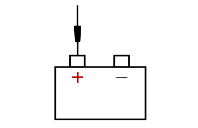
.jpg)
|
Refer to Wiring Diagrams Cell 46 for schematic and connector information. Normal Operation and Fault Conditions The Belt Tension Sensor (BTS) operates in conjunction with the OCS . The OCS interprets a variable voltage signal provided by the Belt Tension Sensor (BTS) to identify the possible presence of a child safety seat in the front passenger seat. The voltage output of the Belt Tension Sensor (BTS) is proportional to the amount of tension applied to the sensor by the belt: no belt tension causes a low voltage (approximately 0.95 volt) to be output and high belt tension causes a high voltage (approximately 3.8 volts) to be returned to the OCSM . The OCSM monitors the Belt Tension Sensor (BTS) and related circuits for the following faults:
If a fault is detected, the OCSM stores DTC B0061:11, B0061:12, B0061:13 or B0061:64 in memory and sends a message to the RCM over the HS-CAN2 indicating that an OCS fault is present. Upon receipt of this message, the RCM sets DTC B00A0:09 and sends a message to the IPC to illuminate the airbag warning indicator. DTC Fault Trigger Conditions
Possible Sources
Visual Inspection and Pre-checks
NOTICE: Use the correct probe adapter(s) when making measurements. Failure to use the correct probe adapter(s) may cause damage to the connector. NOTE: Most faults are due to connector and/or wiring concerns. Carry out a thorough inspection and verification before proceeding with the pinpoint test. NOTE: Only disconnect or reconnect SRS components when instructed to do so within a pinpoint test step. Failure to follow this instruction may result in incorrect diagnosis of the SRS . NOTE: Always make sure the correct SRS component is being installed. Parts released for other vehicles may not be compatible even if they appear physically similar. Check the part number listed in the Ford parts catalog to make sure the correct component is being installed. If an incorrect SRS component is installed, Diagnostic Trouble Codes (DTCs) may set. NOTE: The SRS must be fully operational and free of faults before releasing the vehicle to the customer. |
|||||||||||||||||||
| AX1 RETRIEVE OCSM (OCCUPANT CLASSIFICATION SYSTEM MODULE) DIAGNOSTIC TROUBLE CODES (DTCS) | |||||||||||||||||||
Was DTC B0061:11, B0061:12, B0061:13 or B0061:64 retrieved on-demand during self-test?
|
|||||||||||||||||||
| AX2 CHECK THE BELT TENSION SENSOR (BTS) | |||||||||||||||||||
|
NOTE: This pinpoint test step attempts to change the fault reported by the OCSM by inducing a different fault condition. If the fault reported changes, this indicates the OCSM is functioning correctly and is not the source of the fault.
Was DTC B0061:11 retrieved on-demand during self-test?
|
|||||||||||||||||||
| AX3 CHECK THE BELT TENSION SENSOR (BTS) CIRCUIT FOR A SHORT TO GROUND | |||||||||||||||||||
Is the resistance greater than 10,000 ohms?
|
|||||||||||||||||||
| AX4 CHECK THE BELT TENSION SENSOR (BTS) VREF CIRCUIT FOR AN OPEN | |||||||||||||||||||
Is the resistance less than 0.5 ohm?
|
|||||||||||||||||||
| AX5 CHECK THE BELT TENSION SENSOR (BTS) SIGNAL CIRCUIT FOR A SHORT TO VOLTAGE | |||||||||||||||||||
Is any voltage present?
|
|||||||||||||||||||
| AX6 CHECK THE BELT TENSION SENSOR (BTS) GROUND CIRCUIT FOR AN OPEN | |||||||||||||||||||
Is the resistance less than 3 ohms?
|
|||||||||||||||||||
| AX7 CHECK THE BELT TENSION SENSOR (BTS) | |||||||||||||||||||
|
NOTE: This pinpoint test step will attempt to change the fault reported by the OCSM by inducing a different fault condition. If the fault reported changes, this indicates the OCSM is functioning correctly and is not the source of the fault.
Did the on-demand DTC change from B0061:13 to B0061:11?
|
|||||||||||||||||||
| AX8 CHECK THE BELT TENSION SENSOR (BTS) SIGNAL CIRCUIT FOR AN OPEN | |||||||||||||||||||
Is the resistance less than 0.5 ohm?
|
|||||||||||||||||||
| AX9 CHECK THE BELT TENSION SENSOR (BTS) SIGNAL CIRCUIT FOR A SHORT TO THE BELT TENSION SENSOR (BTS) VREF CIRCUIT | |||||||||||||||||||
|
Is the resistance greater than 10,000 ohms?
|
|||||||||||||||||||
| AX10 CHECK BELT TENSION SENSOR (BTS) VOLTAGE OUTPUT | |||||||||||||||||||
Does the voltage vary from approximately 0.95 volt with no tension applied to the sensor to approximately 3.8 volts with full tension applied to the sensor?
|
|||||||||||||||||||
| AX11 CONFIRM THE OCSM (OCCUPANT CLASSIFICATION SYSTEM MODULE) FAULT | |||||||||||||||||||
|
NOTE: Make sure all OCS components, SRS electrical connectors and the RCM electrical connectors are connected before carrying out the self-test. If not, Diagnostic Trouble Codes (DTCs) will be recorded.
Was the original DTC retrieved on-demand during self-test?
|
|||||||||||||||||||
| AX12 CHECK FOR AN INTERMITTENT FAULT | |||||||||||||||||||
Was DTC B0061:11, B0061:12, B0061:13 or B0061:64 retrieved on-demand during self-test?
|
|||||||||||||||||||
| AX13 CHECK FOR ADDITIONAL SRS (SUPPLEMENTAL RESTRAINT SYSTEM) DIAGNOSTIC TROUBLE CODES (DTCS) | |||||||||||||||||||
Are any RCM or OCSM Diagnostic Trouble Codes (DTCs) retrieved on-demand during self-test?
|
.jpg) C3238 , pin 2, harness side
C3238 , pin 2, harness side
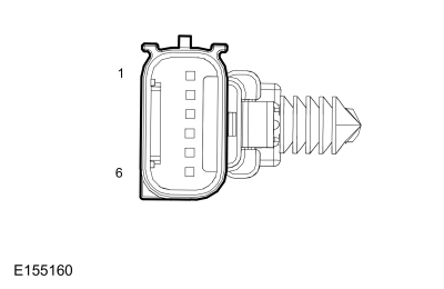 C3238, pin 2, component side
|
Normal Operation and Fault Conditions The OCS sensor is internal to the OCSM and cannot be serviced
separately. For more information refer to REFER to: Airbag and Seatbelt
Pretensioner Supplemental Restraint System (SRS) - System Operation and
Component Description (501-20B Supplemental Restraint System,
Description and Operation). DTC Fault Trigger Conditions
Possible Sources
Visual Inspection and Pre-checks
|
||||||||||||||||||
| AY1 CHECK THE OCS (OCCUPANT CLASSIFICATION SYSTEM) SENSOR INSTALLATION | ||||||||||||||||||
Were any concerns found?
|
|
Refer to Wiring Diagrams Cell 46 for schematic and connector information. Normal Operation and Fault Conditions The OCS determines if the passenger airbag needs to be deployed in the event of a crash by monitoring the pressure that is applied to the OCS bladder when weight of any occupant or object in the front passenger seat is present. When the vehicle is equipped with the front seat massage feature, the pressure that is applied to the OCS bladder can be affected by the operation of the front seat massage function. To account for this, the OCSM monitors various messages sent over HS-CAN from the SCMH indicating the percentage of inflation for each bladder. There are a total of 6 bladders in the passenger seat cushion: 2 for the seat cushion side bolster bladders and 4 for the seat cushion massage function. Under normal operation, the seat cushion massage bladders deflate when the system is not in use. When the OCSM receives HS-CAN messages that indicate the seat massage function is disabled, but the bladders in the seat remain inflated beyond a certain threshold, it sets a DTC . Depending on the amount (percentage) of inflation that remains and the occupancy status of the seat, the OCSM may send a message to the RCM to indicate that a fault is present. If this occurs, the RCM sets DTC B00A0:68 and sends a message to the IPC to illuminate the airbag warning indicator. DTC Fault Trigger Conditions
Possible Sources
Visual Inspection and Pre-checks
NOTICE: Use the correct probe adapter(s) when making measurements. Failure to use the correct probe adapter(s) may cause damage to the connector. NOTE: Most faults are due to connector and/or wiring concerns. Carry out a thorough inspection and verification before proceeding with the pinpoint test. NOTE: Only disconnect or reconnect SRS components when instructed to do so within a pinpoint test step. Failure to follow this instruction may result in incorrect diagnosis of the SRS . NOTE: Always make sure the correct SRS component is being installed. Parts released for other vehicles may not be compatible even if they appear physically similar. Check the part number listed in the Ford parts catalog to make sure the correct component is being installed. If an incorrect SRS component is installed, Diagnostic Trouble Codes (DTCs) may set. NOTE: The SRS must be fully operational and free of faults before releasing the vehicle to the customer. |
||||||
| AZ1 VERIFY THE OCSM (OCCUPANT CLASSIFICATION SYSTEM MODULE) DIAGNOSTIC TROUBLE CODES (DTCS) | ||||||
Was DTC B00A0:62 retrieved on-demand during self-test?
|
||||||
| AZ2 VERIFY THE SEAT CUSHION MASSAGE FUNCTION OPERATES CORRECTLY | ||||||
Does each seat cushion bladder inflate and deflate as the seat cushion massage function operates?
|
||||||
| AZ3 VERIFY THE SEAT CUSHION MASSAGE BLADDERS DEFLATE WHEN DISABLED | ||||||
Do the seat cushion bladder Parameter Identifications (PIDs) all read within 0.2 psi of the side bolster bladder Parameter Identifications (PIDs)?
|
||||||
| AZ4 CHECK FOR AN INTERMITTENT FAULT | ||||||
Was DTC B00A0:62 retrieved on-demand during self-test?
|
||||||
| AZ5 CHECK FOR ADDITIONAL SRS (SUPPLEMENTAL RESTRAINT SYSTEM) DIAGNOSTIC TROUBLE CODES (DTCS) | ||||||
Are any RCM or OCSM Diagnostic Trouble Codes (DTCs) retrieved on-demand during self-test?
|
|
Refer to Wiring Diagrams Cell 46 for schematic and connector information. Normal Operation and Fault Conditions The Belt Tension Sensor (BTS) operates in conjunction with the OCS . The OCSM provides a reference voltage to the Belt Tension Sensor (BTS), which changes as it passes through the sensor, based on how much tension is applied to the seatbelt and Belt Tension Sensor (BTS). The OCSM monitors the Belt Tension Sensor (BTS) reference voltage circuit for a short to voltage or a short to ground. If a fault is detected, the OCSM stores DTC B00C2:11 or B00C2:12 in memory and sends a message to the RCM over the HS-CAN2 indicating that an OCS fault is present. Upon receipt of this message, the RCM sets DTC B00A0:09 and sends a message to the IPC to illuminate the airbag warning indicator. DTC Fault Trigger Conditions
Possible Sources
Visual Inspection and Pre-checks
NOTICE: Use the correct probe adapter(s) when making measurements. Failure to use the correct probe adapter(s) may cause damage to the connector. NOTE: Most faults are due to connector and/or wiring concerns. Carry out a thorough inspection and verification before proceeding with the pinpoint test. NOTE: Only disconnect or reconnect SRS components when instructed to do so within a pinpoint test step. Failure to follow this instruction may result in incorrect diagnosis of the SRS . NOTE: Always make sure the correct SRS component is being installed. Parts released for other vehicles may not be compatible even if they appear physically similar. Check the part number listed in the Ford parts catalog to make sure the correct component is being installed. If an incorrect SRS component is installed, Diagnostic Trouble Codes (DTCs) may set. NOTE: The SRS must be fully operational and free of faults before releasing the vehicle to the customer. |
||||||||||
| BA1 RETRIEVE OCSM (OCCUPANT CLASSIFICATION SYSTEM MODULE) DIAGNOSTIC TROUBLE CODES (DTCS) | ||||||||||
Was DTC B00C2:11 or B00C2:12 retrieved on-demand during self-test?
|
||||||||||
| BA2 CHECK THE BELT TENSION SENSOR (BTS) | ||||||||||
|
NOTE: This pinpoint test step attempts to change the fault reported by the OCSM by inducing a different fault condition. If the fault reported changes, this indicates the OCSM is functioning correctly and is not the source of the fault.
Was DTC B00C2:11 retrieved on-demand during self-test?
|
||||||||||
| BA3 CHECK THE BELT TENSION SENSOR (BTS) VREF CIRCUIT FOR A SHORT TO GROUND | ||||||||||
|
Is the resistance greater than 10,000 ohms?
|
||||||||||
| BA4 CHECK THE BELT TENSION SENSOR (BTS) VREF CIRCUIT FOR A SHORT TO VOLTAGE | ||||||||||
Is any voltage present?
|
||||||||||
| BA5 CONFIRM THE OCSM (OCCUPANT CLASSIFICATION SYSTEM MODULE) FAULT | ||||||||||
|
NOTE: Make sure all OCS system components, restraint system sensor electrical connectors and the RCM electrical connectors are connected before carrying out the self-test. If not, Diagnostic Trouble Codes (DTCs) will be recorded.
Was the original DTC retrieved on-demand during self-test?
|
||||||||||
| BA6 CHECK FOR AN INTERMITTENT FAULT | ||||||||||
Was DTC B00C2:11 or B00C2:12 retrieved on-demand during self-test?
|
||||||||||
| BA7 CHECK FOR ADDITIONAL SRS (SUPPLEMENTAL RESTRAINT SYSTEM) DIAGNOSTIC TROUBLE CODES (DTCS) | ||||||||||
Are any RCM or OCSM Diagnostic Trouble Codes (DTCs) retrieved on-demand during self-test?
|
|
Normal Operation and Fault Conditions
REFER to: Airbag and Seatbelt Pretensioner Supplemental Restraint
System (SRS) - System Operation and Component Description (501-20B
Supplemental Restraint System, Description and Operation). DTC Fault Trigger Conditions
Possible Sources
|
||||||
| BB1 CHECK FOR DIAGNOSTIC TROUBLE CODES (DTCS) | ||||||
Did the DTC return?
|
|
Refer to Wiring Diagrams Cell 46 for schematic and connector information. Normal Operation and Fault Conditions The OCSM and RCM both use information contained in messages from the PCM sent on the HS-CAN . DTC Fault Trigger Conditions
Possible Sources
NOTICE: Use the correct probe adapter(s) when making measurements. Failure to use the correct probe adapter(s) may cause damage to the connector. NOTE: Most faults are due to connector and/or wiring concerns. Carry out a thorough inspection and verification before proceeding with the pinpoint test. NOTE: Only disconnect or reconnect SRS components when instructed to do so within a pinpoint test step. Failure to follow this instruction may result in incorrect diagnosis of the SRS . NOTE: Always make sure the correct SRS component is being installed. Parts released for other vehicles may not be compatible even if they appear physically similar. Check the part number listed in the Ford parts catalog to make sure the correct component is being installed. If an incorrect SRS component is installed, Diagnostic Trouble Codes (DTCs) may set. NOTE: The SRS must be fully operational and free of faults before releasing the vehicle to the customer. |
|||||||||
| BC1 VERIFY DIAGNOSTIC SCAN TOOL COMMUNICATION WITH THE PCM (POWERTRAIN CONTROL MODULE) | |||||||||
|
Can a vehicle session be established?
|
|||||||||
| BC2 CHECK THE OCSM (OCCUPANT CLASSIFICATION SYSTEM MODULE) CONTINUOUS MEMORY DIAGNOSTIC TROUBLE CODES (CMDTCS) | |||||||||
Is DTC U0100:00 retrieved again?
|
|||||||||
| BC3 CHECK THE RCM (RESTRAINTS CONTROL MODULE) CONTINUOUS MEMORY DIAGNOSTIC TROUBLE CODES (CMDTCS) | |||||||||
Is DTC U0100:00 retrieved again?
|
|||||||||
| BC4 RETRIEVE THE RECORDED DIAGNOSTIC TROUBLE CODES (DTCS) FROM THE PCM (POWERTRAIN CONTROL MODULE) KOEO (KEY ON, ENGINE OFF) SELF-TEST | |||||||||
Is DTC P0562 or P0563 recorded?
|
|||||||||
| BC5 RETRIEVE THE RECORDED DIAGNOSTIC TROUBLE CODES (DTCS) FROM THE OCSM (OCCUPANT CLASSIFICATION SYSTEM MODULE) SELF-TEST | |||||||||
Is DTC U3003:16 or U3003:17 recorded?
|
|||||||||
| BC6 RETRIEVE THE RECORDED DIAGNOSTIC TROUBLE CODES (DTCS) FROM THE RCM (RESTRAINTS CONTROL MODULE) SELF-TEST | |||||||||
Is DTC U3003:16 or U3003:17 recorded?
|
|||||||||
| BC7 CHECK FOR DTC (DIAGNOSTIC TROUBLE CODE) U0100:00 SET IN MODULES OTHER THAN THE OCSM (OCCUPANT CLASSIFICATION SYSTEM MODULE) | |||||||||
Is DTC U0100:00 set in the ABS module or in the RCM ?
|
|||||||||
| BC8 CHECK FOR DTC (DIAGNOSTIC TROUBLE CODE) U0100:00 SET IN OTHER MODULES OTHER THAN THE RCM (RESTRAINTS CONTROL MODULE) | |||||||||
Is DTC U0100:00 set in the ABS module or in the OCSM ?
|
|
Refer to Wiring Diagrams Cell 46 for schematic and connector information. Normal Operation and Fault Conditions The OCSM uses information contained in messages from the RCM sent on the HS-CAN2 . DTC Fault Trigger Conditions
Possible Sources
NOTE: Most faults are due to connector and/or wiring concerns. Carry out a thorough inspection and verification before proceeding with the pinpoint test. NOTE: SRS components should only be disconnected or reconnected when instructed to do so within a pinpoint test step. Failure to follow this instruction may result in incorrect diagnosis of the SRS . NOTE: Always make sure the correct SRS component is being installed. Parts released for other vehicles may not be compatible even if they appear physically similar. Check the part number listed in the Ford parts catalog to make sure the correct component is being installed. If an incorrect SRS component is installed, Diagnostic Trouble Codes (DTCs) may set. |
||||||
| BD1 CHECK THE COMMUNICATION NETWORK | ||||||
Does the RCM pass the network test?
|
||||||
| BD2 CHECK THE OCSM (OCCUPANT CLASSIFICATION SYSTEM MODULE) CONTINUOUS MEMORY DIAGNOSTIC TROUBLE CODES (CMDTCS) | ||||||
Is DTC U0151:00 retrieved again?
|
||||||
| BD3 RETRIEVE THE RECORDED DIAGNOSTIC TROUBLE CODES (DTCS) FROM THE RCM (RESTRAINTS CONTROL MODULE) SELF-TEST | ||||||
Is DTC U3003:16 or U3003:17 recorded?
|
||||||
| BD4 RETRIEVE THE RECORDED DIAGNOSTIC TROUBLE CODES (DTCS) FROM THE OCSM (OCCUPANT CLASSIFICATION SYSTEM MODULE) SELF-TEST | ||||||
Is DTC U3003:16 or U3003:17 recorded?
|
||||||
| BD5 CHECK FOR DTC (DIAGNOSTIC TROUBLE CODE) U0151:00 SET IN OTHER MODULES | ||||||
Is DTC U0151:00 set in the ABS module or in the BCM ?
|
|
NOTE: This DTC sets in a module that is reporting a missing or invalid message from another module on the data bus. The module that reports the fault is not the problem module. Do not install a new OCSM as part of the repair unless directed to do so in a pinpoint test. Refer to Wiring Diagrams Cell 46 for schematic and connector information. Normal Operation and Fault Conditions The OCSM receives data messages from the PCM over the HS-CAN DTC Fault Trigger Conditions
Possible Sources
NOTE: SRS components should only be disconnected or reconnected when instructed to do so within a pinpoint test step. Failure to follow this instruction may result in incorrect diagnosis of the SRS . NOTE: Always make sure the correct SRS component is being installed. Parts released for other vehicles may not be compatible even if they appear physically similar. Check the part number listed in the Ford parts catalog to make sure the correct component is being installed. If an incorrect SRS component is installed, Diagnostic Trouble Codes (DTCs) may set. NOTE: The SRS must be fully operational and free of faults before releasing the vehicle to the customer. |
||||||
| BE1 RETRIEVE ALL CONTINUOUS MEMORY DIAGNOSTIC TROUBLE CODES (CMDTCS) IN ALL MODULES | ||||||
|
Are any PCM Diagnostic Trouble Codes (DTCs) retrieved?
|
|
Normal Operation and Fault Conditions The OCS sensor is internal to the OCSM and cannot be serviced
separately. For more information refer to REFER to: Airbag and Seatbelt
Pretensioner Supplemental Restraint System (SRS) - System Operation and
Component Description (501-20B Supplemental Restraint System,
Description and Operation). DTC Fault Trigger Conditions
Possible Sources
NOTICE: Use the correct probe adapter(s) when making measurements. Failure to use the correct probe adapter(s) may cause damage to the connector. NOTE: Most faults are due to connector and/or wiring concerns. Carry out a thorough inspection and verification before proceeding with the pinpoint test. NOTE: Only disconnect or reconnect SRS components when instructed to do so within a pinpoint test step. Failure to follow this instruction may result in incorrect diagnosis of the SRS . NOTE: Always make sure the correct SRS component is being installed. Parts released for other vehicles may not be compatible even if they appear physically similar. Check the part number listed in the Ford parts catalog to make sure the correct component is being installed. If an incorrect SRS component is installed, Diagnostic Trouble Codes (DTCs) may set. NOTE: The SRS must be fully operational and free of faults before releasing the vehicle to the customer. |
||||||||||||
| BF1 CHECK FOR DIAGNOSTIC TROUBLE CODES (DTCS) | ||||||||||||
Did the DTC return?
|
|
Normal Operation and Fault Conditions The OCS sensor is internal to the OCSM and cannot be serviced
separately. For more information refer to REFER to: Airbag and Seatbelt
Pretensioner Supplemental Restraint System (SRS) - System Operation and
Component Description (501-20B Supplemental Restraint System,
Description and Operation). DTC Fault Trigger Conditions
Possible Sources
Visual Inspection and Pre-checks
NOTICE: Use the correct probe adapter(s) when making measurements. Failure to use the correct probe adapter(s) may cause damage to the connector. NOTE: Most faults are due to connector and/or wiring concerns. Carry out a thorough inspection and verification before proceeding with the pinpoint test. NOTE: Only disconnect or reconnect SRS components when instructed to do so within a pinpoint test step. Failure to follow this instruction may result in incorrect diagnosis of the SRS . NOTE: Always make sure the correct SRS component is being installed. Parts released for other vehicles may not be compatible even if they appear physically similar. Check the part number listed in the Ford parts catalog to make sure the correct component is being installed. If an incorrect SRS component is installed, Diagnostic Trouble Codes (DTCs) may set. NOTE: The SRS must be fully operational and free of faults before releasing the vehicle to the customer. |
||||||
| BG1 PERFORM OCS (OCCUPANT CLASSIFICATION SYSTEM) RESET | ||||||
Was the OCS Reset successful?
|
||||||
| BG2 CHECK THE OCS (OCCUPANT CLASSIFICATION SYSTEM) SENSOR INSTALLATION | ||||||
Were any concerns found?
|
||||||
| BG3 RETRIEVE OCS (OCCUPANT CLASSIFICATION SYSTEM) DIAGNOSTIC TROUBLE CODES (DTCS) | ||||||
Did the DTC return?
|
|
Normal Operation and Fault Conditions
REFER to: Airbag and Seatbelt Pretensioner Supplemental Restraint
System (SRS) - System Operation and Component Description (501-20B
Supplemental Restraint System, Description and Operation). DTC Fault Trigger Conditions
Possible Sources
NOTICE: Use the correct probe adapter(s) when making measurements. Failure to use the correct probe adapter(s) may cause damage to the connector. NOTE: Most faults are due to connector and/or wiring concerns. Carry out a thorough inspection and verification before proceeding with the pinpoint test. NOTE: Only disconnect or reconnect SRS components when instructed to do so within a pinpoint test step. Failure to follow this instruction may result in incorrect diagnosis of the SRS . NOTE: Always make sure the correct SRS component is being installed. Parts released for other vehicles may not be compatible even if they appear physically similar. Check the part number listed in the Ford parts catalog to make sure the correct component is being installed. If an incorrect SRS component is installed, Diagnostic Trouble Codes (DTCs) may set. NOTE: The SRS must be fully operational and free of faults before releasing the vehicle to the customer. |
||||||||||||
| BH1 RETRIEVE ALL CONTINUOUS MEMORY DIAGNOSTIC TROUBLE CODES (CMDTCS) IN ALL MODULES | ||||||||||||
|
Are any RCM Diagnostic Trouble Codes (DTCs) retrieved?
|
|
Refer to Wiring Diagrams Cell 46 for schematic and connector information. Normal Operation and Fault Conditions If the RCM detects a fault with the SRS it sends a message to the
IPC to illuminate the Airbag Warning indicator. If the IPC
detects and fault with the Airbag Warning indicator, it will enable a
secondary warning chime. For more information, REFER to: Instrument
Panel Cluster (IPC) - System Operation and Component Description (413-01
Instrumentation, Message Center and Warning Chimes, Description and
Operation). Possible Sources
NOTICE: Use the correct probe adapter(s) when making measurements. Failure to use the correct probe adapter(s) may cause damage to the connector. NOTE: Most faults are due to connector and/or wiring concerns. Carry out a thorough inspection and verification before proceeding with the pinpoint test. NOTE: Only disconnect or reconnect SRS components when instructed to do so within a pinpoint test step. Failure to follow this instruction may result in incorrect diagnosis of the SRS . NOTE: Always make sure the correct SRS component is being installed. Parts released for other vehicles may not be compatible even if they appear physically similar. Check the part number listed in the Ford parts catalog to make sure the correct component is being installed. If an incorrect SRS component is installed, Diagnostic Trouble Codes (DTCs) may set. NOTE: The SRS must be fully operational and free of faults before releasing the vehicle to the customer. |
||||
| BI1 CHECK THE COMMUNICATION NETWORK | ||||
Does the RCM and IPC pass the network test?
|
||||
| BI2 RETRIEVE DIAGNOSTIC TROUBLE CODES (DTCS) | ||||
Were any Diagnostic Trouble Codes (DTCs) retrieved during RCM or IPC self-test?
|

 Clockspring Adjustment. General Procedures
Special Tool(s) /
General Equipment
Adhesive Tape
WARNING:
If the clockspring is not correctly centralized, it may fail
prematurely...
Other information:
Lincoln Nautilus 2018-2026 Owners Manual: Stopping the Liftgate Movement. Liftgate Obstacle Detection. Liftgate – Troubleshooting
Stopping the Liftgate Movement Note: Do not apply sudden excessive force to the liftgate while it is in motion. This could damage the power liftgate and its components. Note: Selections will vary depending on region or options. You can stop the liftgate movement by doing any of the following: Pressing the outside liftgate control button...
Lincoln Nautilus 2018-2026 Service Manual: Module Controlled Functions - Overview. Description and Operation
Body Control Module (BCM) The BCM controls the following: Battery load shed function Battery saver function Brake shift interlock Delayed accessory function Dimmable backlighting Exterior lighting Heated rear windows Heated exterior mirrors Horn Ignition state messaging Interior lighting Keyless entry keypad PATS Perimet..
Categories
- Manuals Home
- 1st Generation Nautilus Owners Manual
- 1st Generation Nautilus Service Manual
- Replacing the Rear Wiper Blades
- Interior Lamp Function. Adjusting the Instrument Panel Lighting Brightness. Ambient Lighting. Interior Lighting – Troubleshooting
- Programming the Garage Door Opener to Your Garage Door Opener Motor
- New on site
- Most important about car
Traction Control
How Does Traction Control Work
If your vehicle begins to slide, the system applies the brakes to individual wheels and, when needed, reduces power at the same time. If the wheels spin when accelerating on slippery or loose surfaces, the system reduces power in order to increase traction.
Switching Traction Control On and Off
WARNING: The stability and traction control light illuminates steadily if the system detects a failure. Make sure you did not manually disable the traction control system using the information display controls or the switch. If the stability control and traction control light is still illuminating steadily, have the system serviced by an authorized dealer immediately. Operating your vehicle with the traction co