Lincoln Nautilus: Climate Control System - General Information / Cabin Heater Coolant Pump - 2.0L EcoBoost (184kW/250PS) – MI4. Removal and Installation
Lincoln Nautilus 2018-2026 Service Manual / Electrical / Climate Control System / Climate Control System - General Information / Cabin Heater Coolant Pump - 2.0L EcoBoost (184kW/250PS) – MI4. Removal and Installation
Special Tool(s) / General Equipment
| Hose Clamp(s) |
Removal
NOTE: Removal steps in this procedure may contain installation details.
-
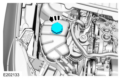
Remove the pressure relief cap. WARNING:
When releasing the cooling system pressure, cover the coolant expansion tank cap with a thick cloth.
WARNING:
When releasing the cooling system pressure, cover the coolant expansion tank cap with a thick cloth.
 |
-
With the vehicle in NEUTRAL, position it on a hoist.
Refer to: Jacking and Lifting - Overview (100-02 Jacking and Lifting, Description and Operation).
-
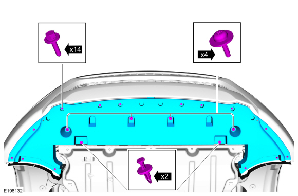
Remove the bolts, the retainers and the front underbody shield.
 |
-
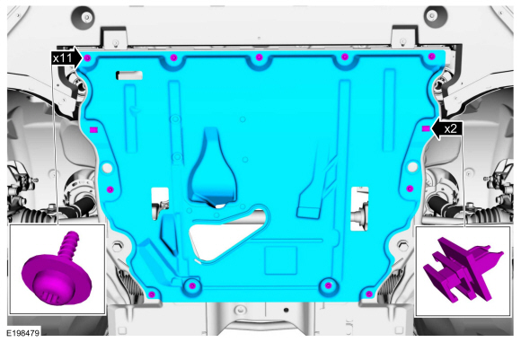
Remove the retainers and the underbody shield.
 |
-
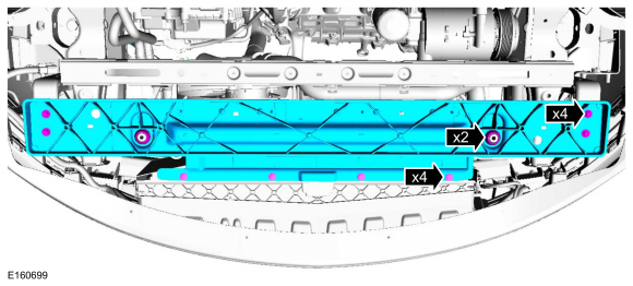
Remove the retainers, bolts and the cooling module support panel.
Torque: 18 lb.ft (24 Nm)
 |
-
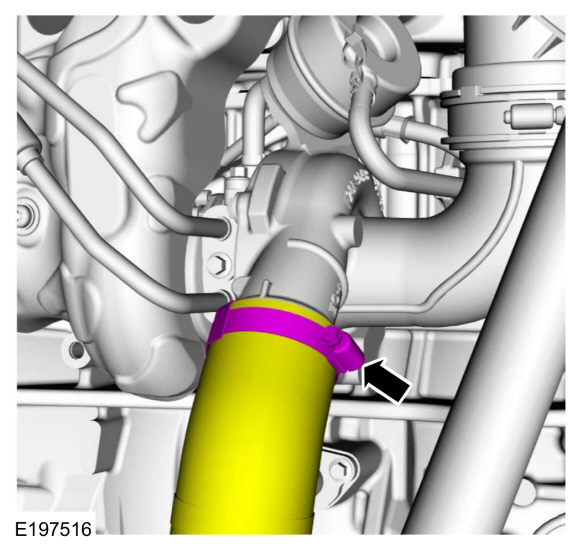
Loosen the clamp and position the CAC tube aside.
Torque: 44 lb.in (5 Nm)
 |
-
-
Release the clamp and disconnect the CAC hose.
-
Disconnect the electrical connector and detach the wire retainer.
-
Release the clamp and disconnect the CAC hose.
 |
-
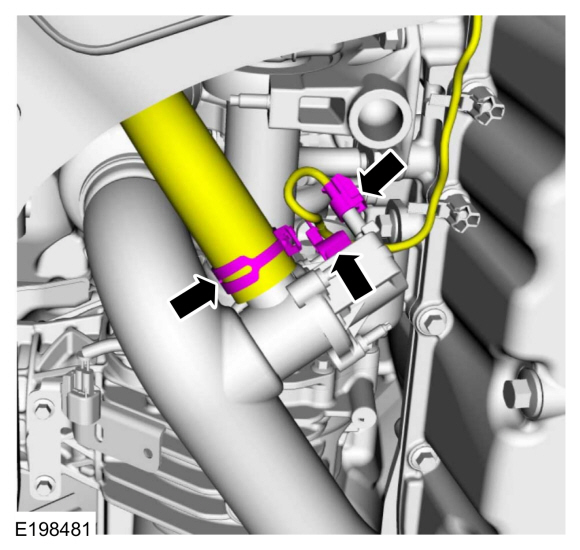
Loosen the clamp and remove the nuts and the CAC tube.
Torque:
1: 44 lb.in (5 Nm)
2: 97 lb.in (11 Nm)
.jpg) |
-
-
Release the clamps and disconnect the heater inlet and outlet hoses.
Use the General Equipment: Hose Clamp(s)
-
Disconnect the electrical connector and detach the wire retainers.
-
Position aside the wiring harness and the heater inlet and outlet hoses.
-
Release the clamps and disconnect the heater inlet and outlet hoses.
.jpg) |
-
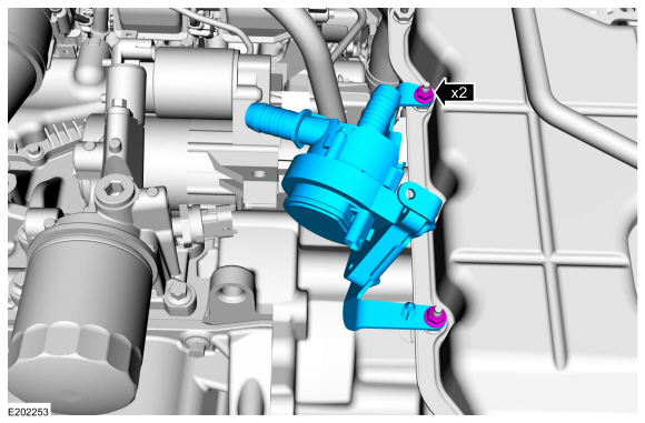
Remove the nuts and the cabin heater coolant pump.
Torque: 80 lb.in (9 Nm)
 |
Installation
-
To install, reverse the removal procedure.
-
Fill and bleed the cooling system.
Refer to: Engine Cooling System Draining, Vacuum Filling and Bleeding (303-03A Engine Cooling - 2.0L EcoBoost (184kW/250PS) – MI4, General Procedures).
 Cabin Air Filter. Removal and Installation
Removal
Fully lower the glove compartment.
Release the tabs.
Disconnect the dampener strap.
Remove the screws and open the cain air filter door...
 Center Registers. Removal and Installation
Special Tool(s) /
General Equipment
Interior Trim Remover
Removal
NOTE:
Removal steps in this procedure may contain installation details...
Other information:
Lincoln Nautilus 2018-2026 Service Manual: Restraints Control Module (RCM). Removal and Installation
Removal WARNING: The following procedure prescribes critical repair steps required for correct restraint system operation during a crash. Follow all notes and steps carefully. Failure to follow step instructions may result in incorrect operation of the restraint system and increases the risk of serious personal injury or death in a crash...
Lincoln Nautilus 2018-2026 Service Manual: Audio Unit Antenna Cable. Removal and Installation
Removal NOTE: The original equipment body and liftgate audio unit antenna cable(s) are part of the wiring harness and cannot be removed. This procedure refers to replacement of the cable(s) only by overlaying the cable(s). NOTE: The instrument panel-to-body audio unit antenna cable inline connection is located under the floor console...
Categories
- Manuals Home
- 1st Generation Nautilus Owners Manual
- 1st Generation Nautilus Service Manual
- Opening and Closing the Hood
- Fuel Quality
- USB Ports
- New on site
- Most important about car
Locating the Pre-Collision Assist Sensors

If a message regarding a blocked sensor or camera appears in the information display, something is obstructing the radar signals or camera images. The radar sensor is behind the fascia cover in the center of the lower grille. With a blocked sensor or camera, the system may not function, or performance may reduce. See Pre-Collision Assist – Information Messages.
Copyright © 2026 www.linautilus.com