Lincoln Nautilus: Rear End Sheet Metal Repairs / Front Floor Panel. Removal and Installation
Special Tool(s) / General Equipment
| Scraper for Straight Edges | |
| Hot Air Gun | |
| 8 mm Drill Bit | |
| MIG/MAG Welding Equipment | |
| Spot Weld Drill Bit | |
| Locking Pliers |
Materials
| Name | Specification |
|---|---|
| Seam Sealer TA-2-B, 3M™ 08308, LORD Fusor® 803DTM |
- |
Removal
NOTE: Roof and body side removed for clarity.
NOTE: Factory welds may be substituted with resistance or metal inert gas (MIG) plug welds. Resistance welds may not be placed directly over original location. They must be placed adjacent to original location and match factory welds in quantity. Metal inert gas (MIG) plug welds must equal factory welds in both location and quantity.
NOTE: Adequately protect all adjacent areas against cutting, grinding and welding procedures.
-
Depower the SRS .
Refer to: Supplemental Restraint System (SRS) Depowering (501-20B Supplemental Restraint System, General Procedures).
-
If Required:
Dimensionally restore the vehicle to pre-damage condition.
Refer to: Body and Frame (501-26 Body Repairs - Vehicle Specific Information and Tolerance Checks, Description and Operation).
-
Remove the instrument panel.
Refer to: Instrument Panel (501-12 Instrument Panel and Console, Removal and Installation).
-
Rmove the front floor panel upper front crossmember.
Refer to: Front Floor Panel Upper Front Crossmember (501-30 Rear End Sheet Metal Repairs, Removal and Installation).
-
Rmove the front floor panel upper rear crossmember.
Refer to: Front Floor Panel Upper Rear Crossmember (501-30 Rear End Sheet Metal Repairs, Removal and Installation).
-
Position the carpet and all wiring harnesses away from the working area.
-
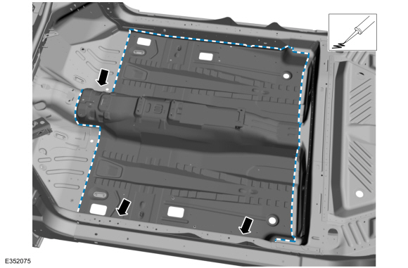
Remove the locally obtained NVH (noise, vibration and harshness) mastic pads.
Use the General Equipment: Hot Air Gun
Use the General Equipment: Scraper for Straight Edges
.jpg) |
-
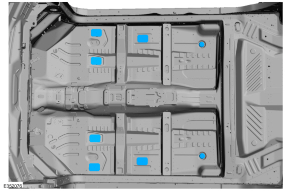
Remove the seam sealer.
Use the General Equipment: Hot Air Gun
Use the General Equipment: Scraper for Straight Edges
.jpg) |
-
Remove the welds.
Use the General Equipment: Spot Weld Drill Bit
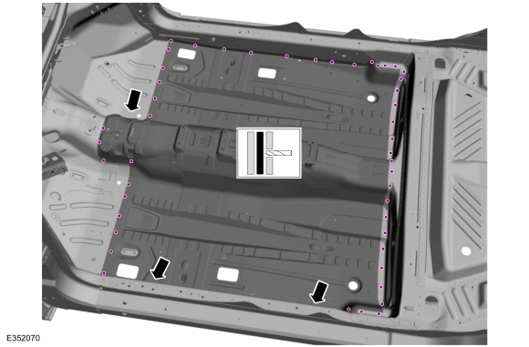 |
-
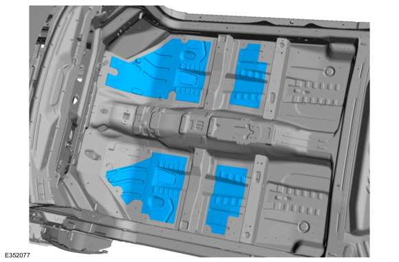
NOTE: Pay particular attention to the location of adhesives and sealers to aid in installation.
Remove the front floor panel.
.jpg) |
Installation
NOTE: Roof and body side removed for clarity.
NOTE: Factory welds may be substituted with resistance or metal inert gas (MIG) plug welds. Resistance welds may not be placed directly over original location. They must be placed adjacent to original location and match factory welds in quantity. Metal inert gas (MIG) plug welds must equal factory welds in both location and quantity.
NOTE: Adequately protect all adjacent areas against cutting, grinding and welding procedures.
-
Drill plug welds holes in the replacement front floor panel.
Use the General Equipment: 8 mm Drill Bit
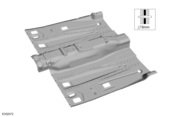 |
-
Install, properly position and clamp the front floor panel.
Use the General Equipment: Locking Pliers
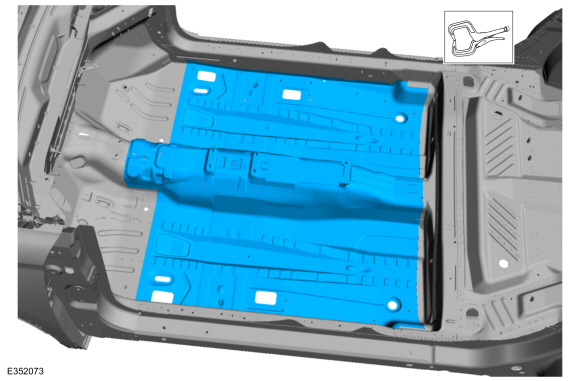 |
-
Install the welds.
Use the General Equipment: MIG/MAG Welding Equipment
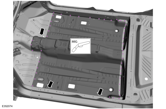 |
-
Dress all welds as required using typical metal finishing techniques.
-
Seam Sealing:
All seams must be sealed to production level.
Material: Seam Sealer / TA-2-B, 3M™ 08308, LORD Fusor® 803DTM
 |
-
Install new or transfer the floor panel plugs.
 |
-
Install locally obtained NVH mastic pads.
 |
-
Refinish the entire repair using a Ford approved paint system.
-
Restore corrosion protection.
Refer to: Corrosion Prevention (501-25 Body Repairs - General Information, General Procedures).
-
Reposition all wiring harnesses and the carpet to original locations.
-
Install the instrument panel.
Refer to: Instrument Panel (501-12 Instrument Panel and Console, Removal and Installation).
-
Install the front floor panel upper front crossmenber.
Refer to: Front Floor Panel Upper Front Crossmember (501-30 Rear End Sheet Metal Repairs, Removal and Installation).
-
Install the front floor panel upper rear crossmenber.
Refer to: Front Floor Panel Upper Rear Crossmember (501-30 Rear End Sheet Metal Repairs, Removal and Installation).
-
Repower the SRS .
Refer to: Supplemental Restraint System (SRS) Repowering (501-20B Supplemental Restraint System, General Procedures).

 Front Floor Panel Bracket and Support. Removal and Installation
Special Tool(s) /
General Equipment
8 mm Drill Bit
MIG/MAG Welding Equipment
Spot Weld Drill Bit
Locking Pliers
Materials
Name
Specification
Seam SealerTA-2-B, 3M™ 08308, LORD Fusor® 803DTM
-
Removal
NOTE:
The following components are available separately...
Other information:
Lincoln Nautilus 2018-2026 Owners Manual: Locating the Tire Sealant and Inflator Kit. Tire Sealant and Inflator Kit Components
Locating the Tire Sealant and Inflator Kit The kit is located under the load floor in the rear of the vehicle. Tire Sealant and Inflator Kit Components Air compressor (inside) Selector switch On and Off button Air pressure gauge Sealant bottle and canister Dual purpose hose: air and repair Tire valve connector Accessory power plug Casing/housing Bike/raft/sports ball adapters ..
Lincoln Nautilus 2018-2026 Service Manual: Brake Disc Machining. General Procedures
Repair NOTE: Do not machine the brake discs for any brake noise concern (squeal, squeak, moan, groan, grunt, grind, etc.). Brake disc machining is allowed if one of the below conditions is present; Excessive corrosion/rust and/or pitting on the braking surface. Excessive bluing discoloration and/or heat spots on the braking surface. Scoring of the brake disc surface. NOT..
Categories
- Manuals Home
- 1st Generation Nautilus Owners Manual
- 1st Generation Nautilus Service Manual
- Normal Scheduled Maintenance
- Auto Hold
- Fuel Quality
- New on site
- Most important about car
Traction Control
How Does Traction Control Work
If your vehicle begins to slide, the system applies the brakes to individual wheels and, when needed, reduces power at the same time. If the wheels spin when accelerating on slippery or loose surfaces, the system reduces power in order to increase traction.
Switching Traction Control On and Off
WARNING: The stability and traction control light illuminates steadily if the system detects a failure. Make sure you did not manually disable the traction control system using the information display controls or the switch. If the stability control and traction control light is still illuminating steadily, have the system serviced by an authorized dealer immediately. Operating your vehicle with the traction co