Lincoln Nautilus: Rear End Sheet Metal Repairs / Front Floor Panel Bracket and Support. Removal and Installation
Special Tool(s) / General Equipment
| 8 mm Drill Bit | |
| MIG/MAG Welding Equipment | |
| Spot Weld Drill Bit | |
| Locking Pliers |
Materials
| Name | Specification |
|---|---|
| Seam Sealer TA-2-B, 3M™ 08308, LORD Fusor® 803DTM |
- |
Removal
NOTE: The following components are available separately. Adjust to meet repair needs.
NOTE: Factory welds may be substituted with resistance or metal inert gas (MIG) plug welds. Resistance welds may not be placed directly over original location. They must be placed adjacent to original location and match factory welds in quantity. Metal inert gas (MIG) plug welds must equal factory welds in both location and quantity.
NOTE: Adequately protect all adjacent areas against cutting, grinding and welding procedures.
-
Depower the SRS .
Refer to: Supplemental Restraint System (SRS) Depowering (501-20B Supplemental Restraint System, General Procedures).
-
If Required:
Dimensionally restore the vehicle to pre-damage condition.
Refer to: Body and Frame (501-26 Body Repairs - Vehicle Specific Information and Tolerance Checks, Description and Operation).
-
On Both Sides:
Remove the front seats.
Refer to: Front Seat (501-10A Front Seats, Removal and Installation).
-
Remove the center console.
Refer to: Floor Console (501-12 Instrument Panel and Console, Removal and Installation).
-
On Both Sides:
Remove the B-pillar trim panels.
Refer to: B-Pillar Trim Panel (501-05 Interior Trim and Ornamentation, Removal and Installation).
-
Position the carpet and all wiring harnesses away from the working area.
-
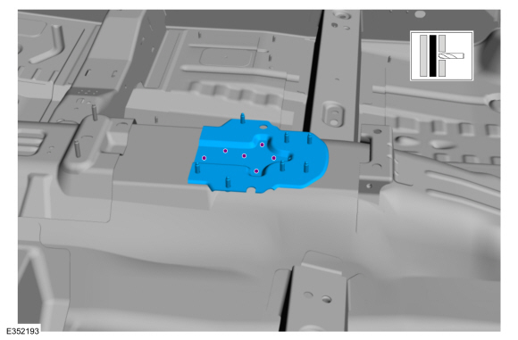
Remove the welds and the bracket.
Use the General Equipment: Spot Weld Drill Bit
 |
-
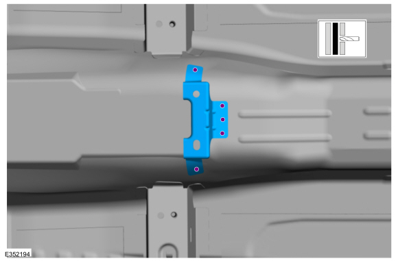
Remove the welds and support.
Use the General Equipment: Spot Weld Drill Bit
 |
Installation
NOTE: The following components are available separately. Adjust to meet repair needs.
NOTE: Factory welds may be substituted with resistance or metal inert gas (MIG) plug welds. Resistance welds may not be placed directly over original location. They must be placed adjacent to original location and match factory welds in quantity. Metal inert gas (MIG) plug welds must equal factory welds in both location and quantity.
NOTE: Adequately protect all adjacent areas against cutting, grinding and welding procedures.
-
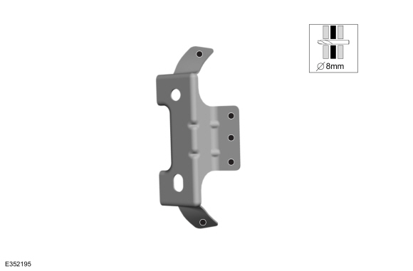
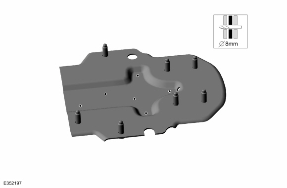
Drill plug weld holes in the replacement support.
Use the General Equipment: 8 mm Drill Bit
 |
-
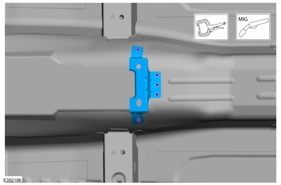
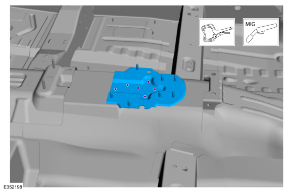
Install, properly position, clamp and weld the support.
Use the General Equipment: Locking Pliers
Use the General Equipment: MIG/MAG Welding Equipment
 |
-
Drill plug weld holes in the replacement bracket.
Use the General Equipment: 8 mm Drill Bit
 |
-
Install, properly position, clamp and weld the bracket.
Use the General Equipment: Locking Pliers
Use the General Equipment: MIG/MAG Welding Equipment
 |
-
Dress all welds as required using typical metal finishing techniques.
-
Seam Sealing:
All seams must be sealed to production level.
Material: Seam Sealer / TA-2-B, 3M™ 08308, LORD Fusor® 803DTM
-
Refinish the entire repair using a Ford approved paint system.
-
Restore corrosion protection.
Refer to: Corrosion Prevention (501-25 Body Repairs - General Information, General Procedures).
-
Reposition all wiring harnesses and the carpet to original locations.
-
Install the center console.
Refer to: Floor Console (501-12 Instrument Panel and Console, Removal and Installation).
-
On Both Sides:
Install the front seats.
Refer to: Front Seat (501-10A Front Seats, Removal and Installation).
-
On Both Sides:
Install the B-pillar trim panels.
Refer to: B-Pillar Trim Panel (501-05 Interior Trim and Ornamentation, Removal and Installation).
-
Repower the SRS .
Refer to: Supplemental Restraint System (SRS) Repowering (501-20B Supplemental Restraint System, General Procedures).
 Front Floor Panel. Removal and Installation
Special Tool(s) /
General Equipment
Scraper for Straight Edges
Hot Air Gun
8 mm Drill Bit
MIG/MAG Welding Equipment
Spot Weld Drill Bit
Locking Pliers
Materials
Name
Specification
Seam SealerTA-2-B, 3M™ 08308, LORD Fusor® 803DTM
-
Removal
NOTE:
Roof and body side removed for clarity...
 Front Floor Panel Lower Reinforcement. Removal and Installation
Special Tool(s) /
General Equipment
8 mm Drill Bit
MIG/MAG Welding Equipment
Spot Weld Drill Bit
Locking Pliers
Materials
Name
Specification
Seam SealerTA-2-B, 3M™ 08308, LORD Fusor® 803DTM
-
Removal
NOTE:
Left hand (LH) side shown, right hand (RH) side similar...
Other information:
Lincoln Nautilus 2018-2026 Owners Manual: Symbols Glossary
SYMBOLS USED ON YOUR VEHICLE These are some of the symbols you may see on your vehicle. Air conditioning system Air conditioning system lubricant type Anti-lock braking system Avoid smoking, flames or sparks Battery Battery acid Brake fluid - non petroleum based Brake system Brake system Cabin air filter Check fuel cap Child safety door lock or unlock Child seat lower anchor Child s..
Lincoln Nautilus 2018-2026 Service Manual: Evaporator. Removal and Installation
Removal Remove the climate control housing. Refer to: Climate Control Housing (412-00 Climate Control System - General Information) . Remove the heater tube dash panel seal. Remove the retainers, release the clip and position the heater tube bracket aside. Remove the heater core. ..
Categories
- Manuals Home
- 1st Generation Nautilus Owners Manual
- 1st Generation Nautilus Service Manual
- Auto Hold
- Massage Seats
- Normal Scheduled Maintenance
- New on site
- Most important about car
Locating the Pre-Collision Assist Sensors

If a message regarding a blocked sensor or camera appears in the information display, something is obstructing the radar signals or camera images. The radar sensor is behind the fascia cover in the center of the lower grille. With a blocked sensor or camera, the system may not function, or performance may reduce. See Pre-Collision Assist – Information Messages.