Lincoln Nautilus: Handles, Locks, Latches and Entry Systems / Handles, Locks, Latches and Entry Systems - System Operation and Component Description. Description and Operation
System Operation
System Diagram
NOTE: The Phone As A Key feature can also be used to lock/unlock the vehicle. Refer to section 419-01C for information regarding this feature.
*.sttxt { visibility: hidden; } *.stcallout { visibility: visible; } 1 Manual Liftgate 2 Liftgate Latch 3 Turn Signals 4 Exterior Sounder 5 BCM 6 GSM 7 IPC 8 FCIM 9 GWM 10 RTM 11 Passive Key 12 Keyless Entry Rear Antenna 13 Exterior Front Door Handles 15 Lock/Unlock Sensors 16 RDM 17 Left Rear Door Latch 18 Lock Actuator 19 Lock Actuator 20 Child Lock Feedback 21 Lock/Unlock Feedback 22 Lock Indicator 23 Right Rear Door Latch 24 Child Lock Feedback 25 Lock/Unlock Feedback 26 Lock Actuator 27 Lock Actuator 28 RDM 29 Lock Indicator 30 Fuel Filler Door Lock Actuator 31 Left Front Door Latch 32 Lock/Unlock Feedback 33 Lock Actuator 34 Lock Indicator 35 Door Lock Control Switch 36 DDM 37 RDM 38 RDM 39 PDM 40 GWM 41 RGTM 42 Lock Indicator 43 Door Lock Control Switch 44 Power Liftgate 45 Lock Actuator 46 Lock/Unlock Feedback 47 Right Front Door Latch 48 Exterior Liftgate Release Switch 49 Keyless Entry Keypad 50 Rear Door Lock Control Switches 51 Exterior Rear Door Handles 52 Lock/Unlock Sensors E348837| Item | Description |
|---|---|
| 1 | Manual Liftgate |
| 2 | Liftgate Latch |
| 3 | Turn Signals |
| 4 | Exterior Sounder |
| 5 | BCM |
| 6 | GSM |
| 7 | IPC |
| 8 | FCIM |
| 9 | GWM |
| 10 | RTM |
| 11 | Passive Key |
| 12 | Keyless Entry Rear Antenna |
| 13 | Exterior Front Door Handles |
| 15 | Lock/Unlock Sensors |
| 16 | RDM |
| 17 | Left Rear Door Latch |
| 18 | Lock Actuator |
| 19 | Lock Actuator |
| 20 | Child Lock Feedback |
| 21 | Lock/Unlock Feedback |
| 22 | Lock Indicator |
| 23 | Right Rear Door Latch |
| 24 | Child Lock Feedback |
| 25 | Lock/Unlock Feedback |
| 26 | Lock Actuator |
| 27 | Lock Actuator |
| 28 | RDM |
| 29 | Lock Indicator |
| 30 | Fuel Filler Door Lock Actuator |
| 31 | Left Front Door Latch |
| 32 | Lock/Unlock Feedback |
| 33 | Lock Actuator |
| 34 | Lock Indicator |
| 35 | Door Lock Control Switch |
| 36 | DDM |
| 37 | RDM |
| 38 | RDM |
| 39 | PDM |
| 40 | GWM |
| 41 | RGTM |
| 42 | Lock Indicator |
| 43 | Door Lock Control Switch |
| 44 | Power Liftgate |
| 45 | Lock Actuator |
| 46 | Lock/Unlock Feedback |
| 47 | Right Front Door Latch |
| 48 | Exterior Liftgate Release Switch |
| 49 | Keyless Entry Keypad |
| 50 | Rear Door Lock Control Switches |
| 51 | Exterior Rear Door Handles |
| 52 | Lock/Unlock Sensors |
Network Message Chart
BCM Network Input Messages
| Broadcast Message | Originating Module | Message Purpose |
|---|---|---|
| Vehicle speed | PCM | The BCM uses the vehicle speed data for the autolock and auto-unlock features. |
| RKE data | RTM | Provides the BCM with the lock/unlock status of the driver door latch. The lock/unlock status is used for the illumination of the door lock status indicator. |
| Door lock switch status | DDM / PDM | Provides the BCM with lock/unlock requests based on the input from the door lock control switch. |
IPC Module Network Input Messages
| Broadcast Message | Originating Module | Message Purpose |
|---|---|---|
| Message center feature configuration | IPC | Provides the BCM configuration settings selected by the driver of the vehicle, such as autolock and auto-unlock settings. |
Power Door Locks
The BCM controls the door locks using a series of integrated relays (driver door unlock/passenger doors unlock/all doors lock). When the relays are not energized, ground is provided on both circuits to the lock motors within the latches. When an unlock relay energizes, voltage is provided to one side of the lock motor to unlock the door(s). When the lock relay energizes, the polarity is reversed and the motors lock the doors.
The DDM and PDM send voltage signals to the front door lock control switches. When a door lock control switch is pressed, the voltage signal is routed to ground, indicating a request to lock/unlock the doors.
When the DDM or PDM detects a lock or unlock request, a message is sent over the CAN to the BCM to lock or unlock the doors.
If equipped, the BCM sends voltage signals to the rear door lock control switches. When a rear door lock control switch is pressed, the voltage signal is routed to ground, indicating a request to lock/unlock the doors. When the BCM detects a lock or unlock request, the BCM energizes the appropriate relays to lock or unlock the doors.
In the event of a power door lock failure, the doors can be individually locked through the manual door lock. The manual door lock is located on the rear edge of the door just above the door latch opening. For the doors on the left side of the vehicle, insert a key and turn clockwise to lock. For the doors on the right side of the vehicle, insert a key and turn counterclockwise to lock.
Based on input from the door lock control switches, the keyless entry keypad (if equipped), the passive entry system (if equipped) and the RKE transmitter, the BCM unlocks the driver door, unlocks all the doors or locks all the doors.
Power Rear Door Child Safety Locks (if equipped)
The power child lock feature is used to electronically activate the rear door child safety locks. This feature operates in conjunction with the rear power windows lock-out feature. When the lock-out switch is placed in the LOCK position with the ignition on, the rear door child safety locks are actuated. A child lock feedback switch is monitored by the corresponding rear door module. When the child lock is activated, the switch opens to indicate the child safety lock is engaged. The rear door module sends the data to the DDM / PDM over a LIN . The DDM / PDM then communicates the child lock feedback to the BCM over the CAN .
Based on the information received, BCM sends a request to the DDM to command on/off the child safety lock indicator located on the master window control switch.
When the power rear door child safety lock has been actuated, the rear door does not open from the interior door handle. The same occurs when the child safety lock is manually actuated.
When the child safety lock is not actuated, the rear door handle must be pulled twice to open the door when locked.
LED Door Lock Indicators
Each door panel has a door lock indicator located on the window sill to indicate the lock or unlock status of that individual door. The door lock indicators are controlled by the lock/unlock feedback switch located within each door latch. When activated, they illuminate to indicate a door is locked and are off when a door is unlocked.
The Light Emitting Diodes (LEDs) are powered continuously when the ignition is on, or for 5 minutes after a lock request if the ignition is off.
The DDM and PDM provide voltage to their respective front door lock indicator and the BCM supplies voltage to the rear door lock indicators.
The lock/unlock feedback switch (within each door latch) provides a ground path to bypass the indicator. The switch is closed when the door is unlocked (indicator not illuminated) and open when locked (indicator illuminated).
The LED door lock indicators are part of the electrical harness and cannot be replaced independently.
Switch Inhibit Feature
The switch inhibit feature prevents unauthorized access to the vehicle from the door lock control switches or the liftgate release switch. The BCM ignores the inputs from all of the door lock control switches and the interior liftgate release switch 20 seconds after the vehicle is electronically locked. If any of these switches are activated while they are inhibited, a chime sounds and a message displays in the message center to indicate the switches are inhibited. The BCM enables the function of these switches when the vehicle is electronically unlocked.
This feature can be configured on/off through the message center.
Power Door Locking Feedback
The exterior lamps and exterior sounder provide visual and audible feedback when unlocking and locking the doors under certain circumstances. Refer to the following table:
NOTE: The mislock feature (if equipped) chimes the exterior sounder twice (no turn signal flash) if the hood, liftgate or any door is ajar when the lock button is pressed on a valid programmed RKE transmitter. This feature can be configured on/off through the message center.
| Action | Status of Door(s) | Status of Liftgate | Status of Hood | Visual/Audible Feedback |
|---|---|---|---|---|
| Press the lock button on the door lock control switch | Open | Closed | Closed | A short flash of the turn signals after all the doors are closed. |
| Press 7/8 and 9/0 on the keyless entry keypad | Closed | Closed | Closed | A short flash of the turn signals and the exterior sounder chimes once. |
| Press the unlock button on a RKE transmitter | Closed | Closed | Closed | A long flash of the turn signals and the exterior sounder chimes twice. |
| Press the lock button on a RKE transmitter | Closed | Closed | Closed | A short flash of the turn signals and the exterior sounder chimes once. |
| Press the lock button on a RKE transmitter | Open | Closed | Closed | The exterior sounder chimes 3 times and then a short flash of the turn signals after all the doors are closed. |
| Press the lock button on a RKE transmitter | Closed | Open | Closed | The exterior sounder chimes 3 times and then a short flash of the turn signals after the liftgate is closed. |
| Press the lock button on a RKE transmitter | Closed | Closed | Open | The exterior sounder chimes 3 times and then a short flash of the turn signals after the hood is closed. |
| Press the liftgate release button twice within 3 seconds on a RKE transmitter | Open or closed | Closed | Open or closed | The exterior sounder chimes 2 times and then releases the liftgate latch (manual liftgate) or opens the liftgate (power liftgate). |
There is also feedback provided by the vehicle to the key for the remote start feature. For additional information regarding the remote start feedback, refer to the Owner's Literature.
The BCM controls the exterior sounder. When requested, the BCM provides voltage to the exterior sounder to actuate it.
Fuel Filler Door Lock (if equipped)
The fuel filler door lock operates in conjunction with the power driver door lock. When the driver door is power locked/unlocked, the fuel filler door is also power locked/unlocked.
Liftgate Latch Release (manual liftgate)
The liftgate latch can be released using:
- the exterior liftgate release switch.
- a valid programmed passive key.
The BCM sends a voltage signal to the exterior liftgate release switch. When the liftgate release switch is pressed, the voltage signal is routed to ground, indicating a request to release the liftgate latch. The BCM momentarily provides voltage to the liftgate latch to actuate the release motor.
When using the liftgate release switch (without a passive key present), the BCM releases the liftgate only when the doors have been electronically unlocked and the vehicle is in PARK.
When using a programmed RKE transmitter, press the liftgate release button twice within 3 seconds to release the liftgate latch. The liftgate latch releases if the vehicle speed is 5 km/h (3.1 mph) or less.
The liftgate latch can also be released using a programmed passive key. Refer to Liftgate Passive Entry in this section.
For power liftgate information,
Refer to: Body Closures - System Operation and Component Description (501-03 Body Closures, Description and Operation).
Keyless Entry Keypad
The keyless entry keypad is integrated into the front door window moulding. The BCM sends voltage signals on 3 separate circuits to the keyless entry keypad. When an individual keypad button is touched, an individual or combination of the input circuits is routed to ground. Based on these inputs, the BCM determines which button was touched. When a valid code is received, the BCM locks/unlocks the doors.
When a keypad button is touched, the buttons illuminate. The keypad illumination turns off after 5 seconds have elapsed since the last button press. The keypad also illuminates any time the illuminated entry feature is active.
The keyless entry keypad can be used to:
- unlock the driver door.
- unlock all the doors.
- lock all the doors (except when the driver door is open).
- program/erase up to 5 user codes.
Locking the Doors with the Keyless Entry Keypad
It is not necessary to enter the factory set or personal code prior to locking all doors. To lock all doors, touch and hold the 7/8 and 9/0 buttons at the same time for approximately 0.5 second. The locking function is disabled when the driver door is open.
Unlocking the Doors with the Keyless Entry Keypad
NOTE: Vehicles equipped with passive entry come from the factory set with the 2-stage unlock feature disabled (all doors unlock when the factory keycode is entered).
To unlock the driver door, enter either the factory set code or a personal code (each digit must be pressed within 5 seconds of the prior digit). The illuminated entry feature activates unless disabled.
If the 2-stage unlock is enabled, enter the factory set code or a personal code (driver door unlocks) and then touch the 3/4 button within 5 seconds to unlock all doors. This feature can be changed to a 1-stage unlock using the message center settings.
Anti-Scan Feature
To provide added security, the keypad is disabled for 1 minute after 36 button presses without a valid entry code being entered. The keypad flashes during this 1 minute mode with all functionality disabled except for 7/8 and 9/0 still being allowed to lock the vehicle.
Anti-scan turns off after 1 minute of keypad inactivity, the unlock button is pressed on a RKE transmitter, a passive entry feature is used, or the ignition is turned on.
Factory Keycode Retrieval
The factory keycode for the keyless entry keypad can be retrieved from a label on the BCM , a wallet card in the Owner's Literature, using a diagnostic scan tool, or by using 2 programmed keys.
To retrieve the factory keycode using 2 programmed keys, carry out the following steps within 10 seconds:
- Place the first valid programmed key into the backup starting location and turn the ignition on.
- Turn the ignition off and remove the first valid programmed key.
- Place the second valid programmed key into the backup starting location and turn the ignition on.
NOTE: Warning messages display in the message center prior to the keycode being displayed.
The factory keycode displays momentarily in the message center.
RKE
The RKE feature is controlled by the BCM . When a button is pressed, the Transmitter Identification Code (TIC) and RKE command is received by the RTM . The RTM interprets the information and sends a message to the BCM over a LIN circuit, and when the network is awake over the CAN . If the BCM detects a valid programmed key, it carries out the command by controlling the door locks, releasing the liftgate latch (or sending a message to the RGTM to open the liftgate) or activating the traffic horn (or the anti-theft alarm horn if equipped with the enhanced security feature), the exterior sounder or turn signals as required.
The RKE system can be used to:
- unlock the driver door.
- unlock all doors.
- lock all doors.
- release the liftgate latch (manual liftgate) or open the liftgate (power liftgate) (liftgate release button must be pressed twice within 3 seconds).
- arm/disarm the perimeter alarm.
- activate/deactivate the panic alarm.
- global open the windows (press the unlock button and then within 10 seconds press and hold the unlock button for 3 seconds) (if equipped).
- global close the windows (press and hold the lock button for 2 seconds) (if equipped).
- remotely start the vehicle.
- configure the staged lock programming (2-stage unlock or global unlock).
The RKE transmitters for a passive key have a normal operating range of 30 m (98 ft) in an open air, no obstruction environment.
The RKE transmitters and the BCM also utilize a rolling code to prevent the code from being captured by a code grabber. The system advances the counter in the RKE transmitter and the BCM every time a RKE transmitter button is pressed.
The message center displays Key Battery Low Replace Soon when the battery in the passive key needs to be replaced.
RKE Transmitter Unlock
The RKE feature provides a staged process for unlocking the doors. Upon receipt of the first request for unlocking the doors, the RKE feature unlocks only the driver door. If another unlock request is received within 3 seconds of the first, all the doors are unlocked. This feature can be disabled so that all the doors unlock on the first press of the unlock button (global unlock) using the message center settings.
Vehicles come from the factory set with the 2-stage unlock feature disabled (single press unlocks all doors).
RKE Transmitter Lock
The RKE feature requests all of the doors lock when the lock button is pressed.
RKE Transmitter Liftgate Latch Release/Power Open
The RKE transmitter provides a liftgate release/power open function. The liftgate release button must be pressed twice within 3 seconds for the liftgate latch to release (manual liftgate) or power open (power liftgate).
Panic Alarm
The panic alarm feature provides audible and visual alarms which are evident from the exterior of the vehicle. When the panic alarm button is initially pressed, the panic alarm feature requests the turn signals flash and the traffic horn (or the anti-theft alarm horn if equipped with the enhanced security feature) sounds for up to 3 minutes or until deactivation. The flashing of the outputs occurs simultaneously.
The panic alarm can only be activated when the ignition is off. This feature is disabled at all other times. Deactivation of an active panic alarm is accomplished when:
- a second press of the RKE transmitter panic button is detected.
- the ignition status changes from off.
- a period of 2 minutes and 45 seconds have elapsed since the initial activation.
To verify if the vehicle is equipped with the enhanced security feature:
- Make sure the correct VIN was entered on the technician service publication website.
- Hover the mouse cursor over or click on the OASIS tab toward the top left corner of the screen.
- Select HVBoM (Historical Vehicle Bill of Material).
- Enter the anti-theft alarm horn part number of “13832” (do not include quotation marks) in the "Limit to Base" field.
-
Press Enter on the keyboard or click on "View BoM (Build of Material)".
- If the vehicle is equipped with the enhanced security feature, 2 rows appear: one indicating "HORN ASY" in the DESCRIPTION column and the other one indicating "HORN ASY-LOW PITCH" in the DESCRIPTION column.
- If the vehicle is not equipped with the enhanced security feature, only one row appears indicating "HORN ASY-LOW PITCH" in the DESCRIPTION column.
Remote Start
The factory-installed remote start allows the vehicle to be remotely started from outside the vehicle. There is a 2-way communication between the passive key and the vehicle to provide the remote start status of the vehicle. The passive key contains a green and a red LED to indicate the remote start status.
| LED | Status |
|---|---|
| Blinking green | Waiting for status update from vehicle |
| Blinking red | Remote start/stop failed |
| Solid green | Remote start or extension successful |
| Solid red | Remote stop successful (engine off) |
To remotely start the vehicle, press the lock button once and then the remote start button twice within 3 seconds of each other. The vehicle should remotely start and the LED on the passive key should be lit solid green.
The vehicle does not remote start if any of the following conditions are present:
- The feature is disabled using the message center settings.
- The hood is not closed.
- The vehicle is not in PARK.
- A powertrain system DTC is present, illuminating the service engine soon indicator.
- The ignition is on.
- The alarm system is triggered.
- The vehicle battery voltage is low.
For additional information regarding the remote start system, refer to the Owner's Literature.
Autolock
The autolock feature locks all of the doors after all of the following have occurred:
- All the doors are closed.
- The ignition is on.
- The vehicle is shifted into any gear to put the vehicle in motion.
- The vehicle attains a speed greater than 20 km/h (12.4 mph).
The auto lock feature activates again during the same ignition cycle when all of the following have occurred:
- The vehicle speed is reduced to less than 15 km/h (9.3 mph).
- A door is opened and then closed.
- The vehicle attains a speed greater than 20 km/h (12.4 mph).
The autolock feature can only be enabled/disabled using a diagnostic scan tool.
To enabled/disable the autolock feature, enter TOOLBOX. Select Module Programming>Programmable Parameters>Power Door Locks. Change all of the settings to Enable or Disable as needed.
Auto-Unlock
NOTE: The doors do not auto-unlock if the vehicle has been electronically locked before the driver door is unlocked.
The auto-unlock feature unlocks all of the doors when all of the following conditions have been met:
- All the doors are closed and locked.
- The ignition was on.
- The vehicle was shifted out of park and a speed greater than 20 km/h (12.4 mph) was achieved.
- The vehicle has come to a stop.
- The ignition transitions to accessory or off and, within 10 minutes, the driver door is opened.
The auto-unlock feature can be enabled/disabled through the message center.
Smart Unlock
The smart unlock feature prevents the vehicle from electronically locking when a valid programmed passive key is left inside the vehicle. When the doors are electronically locked while a door is ajar and then closed, the interior of the vehicle is scanned for a valid programmed passive key. If a valid programmed passive key is detected inside the vehicle, the BCM unlocks the doors and chirps the horn twice.
The smart unlock feature also operates to prevent locking a passive key inside the luggage compartment area. When the liftgate is closed, the interior of the vehicle is scanned for a valid programmed passive key. If a valid programmed passive key is detected inside the luggage compartment area when the liftgate is closed, the BCM releases the liftgate latch (or unlocks the doors) and chirps the horn twice.
To override the smart unlock feature, lock the doors using the keyless entry keypad, the door lock cylinder or another programmed passive key.
Passive Entry
The passive entry feature unlocks or locks the doors or opens the liftgate without having to use a mechanical key blade or the RKE transmitter feature.
When the BCM detects a lock or unlock sensor is touched on an exterior door handle, or the exterior liftgate release button is pressed, it activates the low frequency antenna in the corresponding exterior door handle or inside the luggage compartment area. The low frequency antenna sends out a signal to activate the passive key. The passive key then responds by sending a high frequency signal back to the RTM . The RTM interprets the high frequency signal from the passive key and sends the information to the BCM . If the BCM detects a valid programmed passive key, the BCM unlocks the driver door, unlocks or locks all 4 doors, releases the liftgate latch (manual liftgate) or sends a command to the RGTM to power open the liftgate (power liftgate).
Door Passive Entry
With a programmed passive key within 1 m (3.28 ft) outside a door, touch the lock or unlock sensor on the exterior door handle. The doors lock or unlock depending upon which sensor was touched on the handle. The unlock button is located on the inside of the handle and the lock button is located on the outside top face of the handle.
The driver front door passive entry feature either unlocks the driver door (if 2-staged unlock is enabled) or all four doors (if 2-staged unlock is disabled). The passive entry feature always locks all four doors when the lock button is touched.
The remaining doors passive entry feature always locks or unlocks all four doors.
Liftgate Passive Entry
With a programmed passive key within 1 m (3.28 ft) outside the liftgate, press the exterior liftgate release button on the rear of the vehicle to release the liftgate latch (manual liftgate) or power open the liftgate (power liftgate).
For information regarding the power liftgate hands free feature,
Refer to: Body Closures - System Operation and Component Description (501-03 Body Closures, Description and Operation).
Approach Detection
The approach detection feature is used to passively activate the illuminated entry feature while approaching the vehicle.
To set the vehicle for approach detection, turn the ignition off, exit the vehicle, make sure the liftgate and all the doors are closed and locked. All valid programmed passive keys need to be outside of the area of detection (more than 10 feet) longer than 60 seconds for the BCM to activate the approach detection feature.
When the approach detection feature is active, the BCM uses the passive entry antennas (located in the door handles and at the rear of the vehicle) to detect a valid programmed passive key when approaching within 2.7 m (8.5 ft) of the vehicle. If the BCM detects a valid programmed passive key, it activates the illuminated entry feature.
The approach detection feature is not active/does not activate when:
- a passive key is detected inside the vehicle.
- a passive key is detected in close range of the vehicle for more than 2 minutes.
- the panic/perimeter alarm is triggered.
- the vehicle has not been started for more than 5 days.
- the vehicle battery has a low state of charge.
The approach detection feature can be enabled/disabled through the message center.
Component Description
Door Lock Control Switches
The door lock control switches are double pole, single throw switches. The DDM and PDM provide the voltage signals to the corresponding door lock control switch for the lock and unlock requests. When a switch is pressed to lock or unlock, the corresponding input circuit is routed to ground, indicating a request to lock or unlock the doors.
Door Latches
The door latches are sealed units and contain the door lock actuator(s), the lock/unlock feedback switch, the child safety lock feedback switch and the door ajar switch. The door lock actuators operate in 2 directions, depending on the polarity of the voltage. The door latches can be lubricated, if needed.
Exterior Liftgate Release Switch
The exterior liftgate release switch is a momentary contact switch that supplies a ground signal to the BCM and (if equipped) the RGTM . When the exterior liftgate release switch is pressed, the signal is routed to ground indicating a request to the BCM and the RGTM to release the liftgate latch or power open the liftgate.
Liftgate Latch
The liftgate latch contains the release actuator and the ajar switch. The BCM provides voltage to the actuator to unlatch the liftgate from the striker.
Keyless Entry Keypad
The keyless entry keypad is a touch-sensitive capacitive sensor integrated into the front door window moulding. When a finger touches the keypad, it changes the capacitance of the sensor in the area of the finger touch. The keypad determines which area is touched and provides a ground signal to the corresponding voltage reference circuit(s). The keypad only works when touched with a finger. The keyless entry keypad may not work when gloves are worn. The gloves act as an insulator and do not allow the finger to change the sensor capacitance.
DDM or PDM
The DDM and the PDM monitor the door lock control switches and control the operation of the power windows and the power mirrors. They communicate with each other and the BCM over the CAN .
The DDM and PDM require PMI when replaced.
IKT
The IKT incorporates both the PATS and RKE transmitter functions in a single device.
During key programming procedures, the PATS and RKE transmitter Identification (ID) of a IKT are both programmed. A maximum of 8 keys can be programmed.
Rear Door Module
If equipped, the rear door modules monitor the state of the power child safety door locks and transmit that information to the corresponding front door module (DDM or PDM ).
Exterior Door Handles
The exterior front door handles contain a keyless entry antenna and capacitive touch sensor(s). The antennas and lock/unlock sensors are wired to the BCM . When activated, the antenna transmits a low frequency signal to activate a passive key.
The rear door handles are not equipped with antennas but are equipped with lock/unlock sensors.
Keyless Entry Rear Antenna
The keyless entry rear antenna is wired to the BCM . When activated, it transmits a low frequency signal to activate a passive key.
RTM
The RTM communicates all RKE and passive key information to the BCM over a LIN -based circuit whether or not the CAN is active. The RTM is a receiving antenna that receives the high frequency signals from passive keys.
The RTM requires PMI when replaced.
BCM
The BCM is the master module in control of the power door lock system. It is responsible for locking/unlocking the doors. The BCM receives inputs for the door lock control switches, keys and RKE commands over the CAN and LIN -based circuits.
When the BCM is replaced, the parameter reset and PMI procedures must be carried out and at least 2 keys programmed to it.
 Handles, Locks, Latches and Entry Systems - Overview. Description and Operation
Overview
The
power lock/unlock feature locks or unlocks the doors upon a customer
request from a door lock control switch, the keyless entry keypad, the
passive entry system or a RKE transmitter...
 Locks, Latches and Entry Systems. Diagnosis and Testing
DTC Charts
Diagnostics in this manual assume a certain skill level and knowledge of Ford-specific diagnostic practices. REFER to: Diagnostic Methods (100-00 General Information, Description and Operation)...
Other information:
Lincoln Nautilus 2018-2024 Owners Manual: Active Park Assist – Troubleshooting
Active Park Assist – Information Messages Active Park Assist – Frequently Asked Questions Why does active park assist not operate correctly? The system is unable to detect a vehicle, curb or object to park next to or in between. The system needs boundary objects to operate correctly...
Lincoln Nautilus 2018-2024 Service Manual: C-Pillar Side Impact Sensor. Removal and Installation
Removal WARNING: The following procedure prescribes critical repair steps required for correct restraint system operation during a crash. Follow all notes and steps carefully. Failure to follow step instructions may result in incorrect operation of the restraint system and increases the risk of serious personal injury or death in a crash...
Categories
- Manuals Home
- 1st Generation Nautilus Owners Manual
- 1st Generation Nautilus Service Manual
- Replacing the Rear Wiper Blades
- Auto-Start-Stop
- What Is the Electric Parking Brake. Applying the Electric Parking Brake. Applying the Electric Parking Brake in an Emergency. Manually Releasing the Electric Parking Brake
- New on site
- Most important about car
Replacing the Rear Wiper Blades
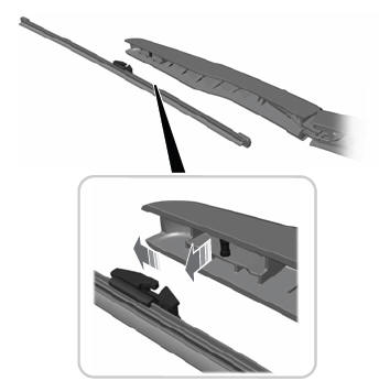
Note: Do not hold the wiper blade to lift the wiper arm.
Remove the wiper blade.