Lincoln Nautilus: Handles, Locks, Latches and Entry Systems / Locks, Latches and Entry Systems. Diagnosis and Testing
DTC Charts
Diagnostics in this manual assume a certain skill level and knowledge of Ford-specific diagnostic practices.
REFER to: Diagnostic Methods (100-00 General Information, Description and Operation).
NOTE: The Phone as a Key feature can be used as a passive entry and remote start feature for the vehicle. Refer to section 419-01C for information regarding this feature.
BCM DTC Chart
| DTC | Description | Action |
|---|---|---|
| B10AB:00 | Remote Keyless Entry Synchronization: No Sub Type Information | GO to Pinpoint Test W |
| B10C7:01 | Interior Trunk Antenna: General Electrical Failure | GO to Pinpoint Test AB |
| B110C:13 | Rear door driver side power child locking motor: Circuit Open |
|
| B110C:62 | Rear door driver side power child locking motor: Signal Compare Failure |
|
| B110D:13 | Rear door passenger side power child locking motor: Circuit Open |
|
| B110D:62 | Rear door passenger side power child locking motor: Signal Compare Failure |
|
| B1218:00 | Transmitter Identification Code: No Sub Type Information | GO to Pinpoint Test W |
| B1219:11 | Interior Boot/Trunk Release Switch: Circuit Short To Ground |
|
| B121A:11 | Keypad Illumination Output: Circuit Short To Ground | GO to Pinpoint Test U |
| B121A:15 | Keypad Illumination Output: Circuit Short To Battery or Open |
|
| B121B:01 | Keypad Input Switch: General Electrical Failure | GO to Pinpoint Test T |
| B126A:01 | Drivers Door Interior Lock Switch: General Electrical Failure | GO to Pinpoint Test J |
| B12EE:11 | Liftgate/Tailgate/Trunk Release: Circuit Short To Ground | GO to Pinpoint Test Q |
| B12EE:15 | Liftgate/Tailgate/Trunk Release: Circuit Short To Battery or Open |
|
| B1336:01 | Driver Door External Antenna: General Electrical Failure | GO to Pinpoint Test AA |
| B1337:01 | Passenger Door External Antenna: General Electrical Failure | GO to Pinpoint Test AA |
| B1381:11 | Left Front Door Handle Proximity Sensor: Circuit Short To Ground | GO to Pinpoint Test AA |
| B1381:15 | Left Front Door Handle Proximity Sensor: Circuit Short To Battery or Open | GO to Pinpoint Test AA |
| B1381:29 | Left Front Door Handle Proximity Sensor: Signal Invalid | GO to Pinpoint Test AA |
| B1382:11 | Right Front Door Handle Proximity Sensor: Circuit Short To Ground | GO to Pinpoint Test AA |
| B1382:15 | Right Front Door Handle Proximity Sensor: Circuit Short To Battery or Open | GO to Pinpoint Test AA |
| B1382:29 | Right Front Door Handle Proximity Sensor: Signal Invalid | GO to Pinpoint Test AA |
| B1383:11 | Left Rear Door Handle Proximity Sensor: Circuit Short To Ground | GO to Pinpoint Test AA |
| B1383:15 | Left Rear Door Handle Proximity Sensor: Circuit Short To Battery or Open | GO to Pinpoint Test AA |
| B1383:29 | Left Rear Door Handle Proximity Sensor: Signal Invalid | GO to Pinpoint Test AA |
| B1384:11 | Right Rear Door Handle Proximity Sensor: Circuit Short To Ground | GO to Pinpoint Test AA |
| B1384:15 | Right Rear Door Handle Proximity Sensor: Circuit Short To Battery or Open | GO to Pinpoint Test AA |
| B1384:29 | Right Rear Door Handle Proximity Sensor: Signal Invalid | GO to Pinpoint Test AA |
| B1490:11 | Lock Indicator LED Status Output: Circuit Short To Ground | GO to Pinpoint Test L |
| B1490:15 | Lock Indicator LED Status Output: Circuit Short To Battery or Open |
|
| B1495:11 | Hands Free Liftgate/Decklid Input Sensor: Circuit Short To Ground |
REFER to: Body Closures (501-03 Body Closures, Diagnosis and Testing). |
| B14B8:11 | Sounder: Circuit Short To Ground | GO to Pinpoint Test R |
| B14B8:15 | Sounder: Circuit Short To Battery or Open |
|
| U0258:87 | Lost Communication With Radio Transceiver: Missing Message | GO to Pinpoint Test AE |
| All other Diagnostic Trouble Codes (DTCs) | - |
REFER to: Body Control Module (BCM) (419-10 Multifunction Electronic Modules, Diagnosis and Testing). |
Diagnostics in this manual assume a certain skill level and knowledge of Ford-specific diagnostic practices.
REFER to: Diagnostic Methods (100-00 General Information, Description and Operation).
RTM DTC Chart
| DTC | Description | Action |
|---|---|---|
| U0146:00 | Lost Communication With Gateway "A": No Sub Type Information | GO to Pinpoint Test AD |
| U1A00:00 | Private Communication Network: No Sub Type Information | GO to Pinpoint Test AE |
| All other Diagnostic Trouble Codes (DTCs) | - |
REFER to: Tire Pressure Monitoring System (TPMS) (204-04B Tire Pressure Monitoring System (TPMS), Diagnosis and Testing). |
Diagnostics in this manual assume a certain skill level and knowledge of Ford-specific diagnostic practices.
REFER to: Diagnostic Methods (100-00 General Information, Description and Operation).
DDM DTC Chart
| DTC | Description | Action |
|---|---|---|
| B1087:83 | LIN Bus "A": Value of Signal Protection Calculation Incorrect | GO to Pinpoint Test AF |
| B1087:87 | LIN Bus "A": Missing Message | GO to Pinpoint Test AF |
| B1088:83 | LIN Bus "B": Value of Signal Protection Calculation Incorrect |
REFER to: Glass, Frames and Mechanisms (501-11 Glass, Frames and Mechanisms, Diagnosis and Testing). |
| B1088:87 | LIN Bus "B": Missing Message |
REFER to: Glass, Frames and Mechanisms (501-11 Glass, Frames and Mechanisms, Diagnosis and Testing). |
| B108F:23 | Cabin Lock/Unlock Switch: Signal Stuck Low | GO to Pinpoint Test J |
| B1163:11 | Left Mirror Heater Output: Circuit Short To Ground |
REFER to: Rear View Mirrors (501-09 Rear View Mirrors, Diagnosis and Testing). |
| B1163:15 | Left Mirror Heater Output: Circuit Short To Battery or Open |
REFER to: Rear View Mirrors (501-09 Rear View Mirrors, Diagnosis and Testing). |
| B1165:11 | Left Front Puddle Lamp Output: Circuit Short To Ground |
REFER to: Interior Lighting (417-02 Interior Lighting, Diagnosis and Testing). |
| B1165:15 | Left Front Puddle Lamp Output: Circuit Short To Battery or Open |
REFER to: Interior Lighting (417-02 Interior Lighting, Diagnosis and Testing). |
| B117C:07 | Rear Power Window Up: Mechanical Failure |
REFER to: Glass, Frames and Mechanisms (501-11 Glass, Frames and Mechanisms, Diagnosis and Testing). |
| B117C:16 | Rear Power Window Up: Circuit Voltage Below Threshold |
REFER to: Glass, Frames and Mechanisms (501-11 Glass, Frames and Mechanisms, Diagnosis and Testing). |
| B117C:4B | Rear Power Window Up: Over Temperature |
REFER to: Glass, Frames and Mechanisms (501-11 Glass, Frames and Mechanisms, Diagnosis and Testing). |
| B117C:92 | Rear Power Window Up: Performance or Incorrect Operation |
REFER to: Glass, Frames and Mechanisms (501-11 Glass, Frames and Mechanisms, Diagnosis and Testing). |
| B117E:07 | Front Power Window Up: Mechanical Failure |
REFER to: Glass, Frames and Mechanisms (501-11 Glass, Frames and Mechanisms, Diagnosis and Testing). |
| B117E:16 | Front Power Window Up: Circuit Voltage Below Threshold |
REFER to: Glass, Frames and Mechanisms (501-11 Glass, Frames and Mechanisms, Diagnosis and Testing). |
| B117E:4B | Front Power Window Up: Over Temperature |
REFER to: Glass, Frames and Mechanisms (501-11 Glass, Frames and Mechanisms, Diagnosis and Testing). |
| B117E:92 | Front Power Window Up: Performance or Incorrect Operation |
REFER to: Glass, Frames and Mechanisms (501-11 Glass, Frames and Mechanisms, Diagnosis and Testing). |
| B1189:29 | Front Window Position Sensor: Signal Invalid |
REFER to: Glass, Frames and Mechanisms (501-11 Glass, Frames and Mechanisms, Diagnosis and Testing). |
| B118A:29 | Rear Window Position Sensor: Signal Invalid |
REFER to: Glass, Frames and Mechanisms (501-11 Glass, Frames and Mechanisms, Diagnosis and Testing). |
| B118C:11 | Left Blind Spot Warning Indicator: Circuit Short To Ground |
REFER to: Blind Spot Information System (419-04 Side and Rear Vision, Diagnosis and Testing). |
| B118C:15 | Left Blind Spot Warning Indicator: Circuit Short To Battery or Open |
REFER to: Blind Spot Information System (419-04 Side and Rear Vision, Diagnosis and Testing). |
| B11DA:23 | Driver Door Key Cylinder Switch: Signal Stuck Low | GO to Pinpoint Test AL |
| B11F6:11 | Driver Folding Mirror Motor: Circuit Short To Ground |
REFER to: Rear View Mirrors (501-09 Rear View Mirrors, Diagnosis and Testing). |
| B11F6:15 | Driver Folding Mirror Motor: Circuit Short To Battery or Open |
REFER to: Rear View Mirrors (501-09 Rear View Mirrors, Diagnosis and Testing). |
| B12C5:71 | Front Window Lifter Motor Up Relay: Actuator Stuck |
REFER to: Glass, Frames and Mechanisms (501-11 Glass, Frames and Mechanisms, Diagnosis and Testing). |
| B12C6:71 | Rear Window Lifter Motor Up Relay: Actuator Stuck |
REFER to: Glass, Frames and Mechanisms (501-11 Glass, Frames and Mechanisms, Diagnosis and Testing). |
| B12C7:71 | Rear Window Lifter Motor Down Relay: Actuator Stuck |
REFER to: Glass, Frames and Mechanisms (501-11 Glass, Frames and Mechanisms, Diagnosis and Testing). |
| B12C8:71 | Front Window Lifter Motor Down Relay: Actuator Stuck |
REFER to: Glass, Frames and Mechanisms (501-11 Glass, Frames and Mechanisms, Diagnosis and Testing). |
| B12E9:24 | Rear Window Local Up/Down Switch: Signal Stuck High |
REFER to: Glass, Frames and Mechanisms (501-11 Glass, Frames and Mechanisms, Diagnosis and Testing). |
| B12FF:11 | Rear Door Switch Illumination: Circuit Short To Ground |
REFER to: Instrument Panel and Interior Switches Illumination (413-00 Instrument Panel and Interior Switches Illumination, Diagnosis and Testing). |
| B12FF:15 | Rear Door Switch Illumination: Circuit Short To Battery or Open |
REFER to: Instrument Panel and Interior Switches Illumination (413-00 Instrument Panel and Interior Switches Illumination, Diagnosis and Testing). |
| B13F0:4B | Left Rear Power Window Motor: Over Temperature |
REFER to: Glass, Frames and Mechanisms (501-11 Glass, Frames and Mechanisms, Diagnosis and Testing). |
| B13F1:4B | Driver Power Window Motor: Over Temperature |
REFER to: Glass, Frames and Mechanisms (501-11 Glass, Frames and Mechanisms, Diagnosis and Testing). |
| B1C03:23 | Memory #1 Switch: Signal Stuck Low |
REFER to: Front Seats (501-10A Front Seats, Diagnosis and Testing). |
| B1C04:23 | Memory #2 Switch: Signal Stuck Low |
REFER to: Front Seats (501-10A Front Seats, Diagnosis and Testing). |
| B1C05:23 | Memory #3 Switch: Signal Stuck Low |
REFER to: Front Seats (501-10A Front Seats, Diagnosis and Testing). |
| B1C09:11 | Driver Left/Right Mirror Motor: Circuit Short To Ground |
REFER to: Rear View Mirrors (501-09 Rear View Mirrors, Diagnosis and Testing). |
| B1C09:15 | Driver Left/Right Mirror Motor: Circuit Short To Battery or Open |
REFER to: Rear View Mirrors (501-09 Rear View Mirrors, Diagnosis and Testing). |
| B1C10:11 | Driver Up/Down Mirror Motor: Circuit Short To Ground |
REFER to: Rear View Mirrors (501-09 Rear View Mirrors, Diagnosis and Testing). |
| B1C10:15 | Driver Up/Down Mirror Motor: Circuit Short To Battery or Open |
REFER to: Rear View Mirrors (501-09 Rear View Mirrors, Diagnosis and Testing). |
| B1C13:11 | Driver Up/Down Mirror Motor Feedback: Circuit Short To Ground |
REFER to: Rear View Mirrors (501-09 Rear View Mirrors, Diagnosis and Testing). |
| B1C13:15 | Driver Up/Down Mirror Motor Feedback: Circuit Short To Battery or Open |
REFER to: Rear View Mirrors (501-09 Rear View Mirrors, Diagnosis and Testing). |
| B1C14:11 | Driver Left/Right Mirror Motor Feedback: Circuit Short To Ground |
REFER to: Rear View Mirrors (501-09 Rear View Mirrors, Diagnosis and Testing). |
| B1C14:15 | Driver Left/Right Mirror Motor Feedback: Circuit Short To Battery or Open |
REFER to: Rear View Mirrors (501-09 Rear View Mirrors, Diagnosis and Testing). |
| B1D06:11 | Left Turn Indicator: Circuit Short To Ground |
REFER to: Turn Signal and Hazard Lamps (417-01 Exterior Lighting, Diagnosis and Testing). |
| C1B14:11 | Sensor Supply Voltage A: Circuit Short To Ground |
REFER to: Glass, Frames and Mechanisms (501-11 Glass, Frames and Mechanisms, Diagnosis and Testing). |
| C1B14:15 | Sensor Supply Voltage A: Circuit Short To Battery or Open |
REFER to: Glass, Frames and Mechanisms (501-11 Glass, Frames and Mechanisms, Diagnosis and Testing). |
| C1B15:11 | Sensor Supply Voltage B: Circuit Short To Ground |
REFER to: Rear View Mirrors (501-09 Rear View Mirrors, Diagnosis and Testing). |
| C1B15:15 | Sensor Supply Voltage B: Circuit Short To Battery or Open |
REFER to: Rear View Mirrors (501-09 Rear View Mirrors, Diagnosis and Testing). |
| U0010:00 | Medium Speed CAN Communication Bus: No Sub Type Information | The module was unable to communicate on the network at a point in time. The fault is not currently present (the module had to communicate with the scan tool to report this DTC ). VERIFY the continuity of the connectors and wiring. Refer to Wiring Diagrams Cell 14 Module Communications Network for schematic and connector information. |
| U0140:00 | Lost Communication With Body Control Module: No Sub Type Information | GO to Pinpoint Test AG |
| U0208:00 | Lost Communication With "Seat Control Module A": No Sub Type Information | GO to Pinpoint Test AH |
| U0232:00 | Lost Communication With Side Obstacle Detection Control Module - Left: No Sub Type Information | GO to Pinpoint Test AI |
| U0300:00 | Internal Control Module Software Incompatibility: No Sub Type Information |
CLEAR the Diagnostic Trouble Codes (DTCs) and REPEAT the self-test. If the DTC is retrieved again, INSTALL a new DDM . REFER to: Driver Door Module (DDM) (419-10 Multifunction Electronic Modules, Removal and Installation). |
| U0300:4A | Internal Control Module Software Incompatibility: Incorrect Component Installed |
CARRY OUT the PMI using as-built data. CLEAR the Diagnostic Trouble
Codes (DTCs) and REPEAT the self-test. If the DTC returns, INSTALL a new
DDM . REFER to: Driver Door Module (DDM) (419-10 Multifunction Electronic Modules, Removal and Installation). |
| U0422:00 | Invalid Data Received From Body Control Module: No Sub Type Information |
RETRIEVE and REPAIR all non-network Diagnostic Trouble Codes (DTCs) from the BCM . REFER to: Body Control Module (BCM) (419-10 Multifunction Electronic Modules, Diagnosis and Testing). |
| U0509:00 | Invalid Data Received From "Seat Control Module A": No Sub Type Information |
RETRIEVE and REPAIR all non-network Diagnostic Trouble Codes (DTCs) from the DSM . REFER to: Front Seats (501-10A Front Seats, Diagnosis and Testing). |
| U2010:00 | Switch Illumination: No Sub Type Information |
REFER to: Instrument Panel and Interior Switches Illumination (413-00 Instrument Panel and Interior Switches Illumination, Diagnosis and Testing). |
| U2013:24 | Switch Pack: Signal Stuck High |
REFER to: Glass, Frames and Mechanisms (501-11 Glass, Frames and Mechanisms, Diagnosis and Testing). |
| U2014:00 | Control Module Hardware: No Sub Type Information |
INSTALL a new DDM . REFER to: Driver Door Module (DDM) (419-10 Multifunction Electronic Modules, Removal and Installation). |
| U2100:00 | Initial Configuration Not Complete: No Sub Type Information |
CARRY OUT the PMI using as-built data. CLEAR the Diagnostic Trouble
Codes (DTCs) and REPEAT the self-test. If the DTC returns, INSTALL a new
DDM . REFER to: Driver Door Module (DDM) (419-10 Multifunction Electronic Modules, Removal and Installation). |
| U3000:04 | Control Module: System Internal Failure |
INSTALL a new DDM . REFER to: Driver Door Module (DDM) (419-10 Multifunction Electronic Modules, Removal and Installation). |
Diagnostics in this manual assume a certain skill level and knowledge of Ford-specific diagnostic practices.
REFER to: Diagnostic Methods (100-00 General Information, Description and Operation).
PDM DTC Chart
| DTC | Description | Action |
|---|---|---|
| B1087:83 | LIN Bus "A": Value of Signal Protection Calculation Incorrect | GO to Pinpoint Test AF |
| B1087:87 | LIN Bus "A": Missing Message | GO to Pinpoint Test AF |
| B108F:23 | Cabin Lock/Unlock Switch: Signal Stuck Low | GO to Pinpoint Test J |
| B1164:11 | Right Mirror Heater Output: Circuit Short To Ground |
REFER to: Rear View Mirrors (501-09 Rear View Mirrors, Diagnosis and Testing). |
| B1164:15 | Right Mirror Heater Output: Circuit Short To Battery or Open |
REFER to: Rear View Mirrors (501-09 Rear View Mirrors, Diagnosis and Testing). |
| B1166:11 | Right Front Puddle Lamp Output: Circuit Short To Ground |
REFER to: Interior Lighting (417-02 Interior Lighting, Diagnosis and Testing). |
| B1166:15 | Right Front Puddle Lamp Output: Circuit Short To Battery or Open |
REFER to: Interior Lighting (417-02 Interior Lighting, Diagnosis and Testing). |
| B117C:07 | Rear Power Window Up: Mechanical Failure |
REFER to: Glass, Frames and Mechanisms (501-11 Glass, Frames and Mechanisms, Diagnosis and Testing). |
| B117C:16 | Rear Power Window Up: Circuit Voltage Below Threshold |
REFER to: Glass, Frames and Mechanisms (501-11 Glass, Frames and Mechanisms, Diagnosis and Testing). |
| B117C:4B | Rear Power Window Up: Over Temperature |
REFER to: Glass, Frames and Mechanisms (501-11 Glass, Frames and Mechanisms, Diagnosis and Testing). |
| B117C:92 | Rear Power Window Up: Performance or Incorrect Operation |
REFER to: Glass, Frames and Mechanisms (501-11 Glass, Frames and Mechanisms, Diagnosis and Testing). |
| B117E:07 | Front Power Window Up: Mechanical Failure |
REFER to: Glass, Frames and Mechanisms (501-11 Glass, Frames and Mechanisms, Diagnosis and Testing). |
| B117E:16 | Front Power Window Up: Circuit Voltage Below Threshold |
REFER to: Glass, Frames and Mechanisms (501-11 Glass, Frames and Mechanisms, Diagnosis and Testing). |
| B117E:4B | Front Power Window Up: Over Temperature |
REFER to: Glass, Frames and Mechanisms (501-11 Glass, Frames and Mechanisms, Diagnosis and Testing). |
| B117E:92 | Front Power Window Up: Performance or Incorrect Operation |
REFER to: Glass, Frames and Mechanisms (501-11 Glass, Frames and Mechanisms, Diagnosis and Testing). |
| B1189:29 | Front Window Position Sensor: Signal Invalid |
REFER to: Glass, Frames and Mechanisms (501-11 Glass, Frames and Mechanisms, Diagnosis and Testing). |
| B118A:29 | Rear Window Position Sensor: Signal Invalid |
REFER to: Glass, Frames and Mechanisms (501-11 Glass, Frames and Mechanisms, Diagnosis and Testing). |
| B118D:11 | Right Blind Spot Warning Indicator: Circuit Short To Ground |
REFER to: Blind Spot Information System (419-04 Side and Rear Vision, Diagnosis and Testing). |
| B118D:15 | Right Blind Spot Warning Indicator: Circuit Short To Battery or Open |
REFER to: Blind Spot Information System (419-04 Side and Rear Vision, Diagnosis and Testing). |
| B11F7:11 | Passenger Folding Mirror Motor: Circuit Short To Ground |
REFER to: Rear View Mirrors (501-09 Rear View Mirrors, Diagnosis and Testing). |
| B11F7:15 | Passenger Folding Mirror Motor: Circuit Short To Battery or Open |
REFER to: Rear View Mirrors (501-09 Rear View Mirrors, Diagnosis and Testing). |
| B12C5:71 | Front Window Lifter Motor Up Relay: Actuator Stuck |
REFER to: Glass, Frames and Mechanisms (501-11 Glass, Frames and Mechanisms, Diagnosis and Testing). |
| B12C6:71 | Rear Window Lifter Motor Up Relay: Actuator Stuck |
REFER to: Glass, Frames and Mechanisms (501-11 Glass, Frames and Mechanisms, Diagnosis and Testing). |
| B12C7:71 | Rear Window Lifter Motor Down Relay: Actuator Stuck |
REFER to: Glass, Frames and Mechanisms (501-11 Glass, Frames and Mechanisms, Diagnosis and Testing). |
| B12C8:71 | Front Window Lifter Motor Down Relay: Actuator Stuck |
REFER to: Glass, Frames and Mechanisms (501-11 Glass, Frames and Mechanisms, Diagnosis and Testing). |
| B12E9:24 | Rear Window Local Up/Down Switch: Signal Stuck High |
REFER to: Glass, Frames and Mechanisms (501-11 Glass, Frames and Mechanisms, Diagnosis and Testing). |
| B12FF:11 | Rear Door Switch Illumination: Circuit Short To Ground |
REFER to: Instrument Panel and Interior Switches Illumination (413-00 Instrument Panel and Interior Switches Illumination, Diagnosis and Testing). |
| B12FF:15 | Rear Door Switch Illumination: Circuit Short To Battery or Open |
REFER to: Instrument Panel and Interior Switches Illumination (413-00 Instrument Panel and Interior Switches Illumination, Diagnosis and Testing). |
| B12EF:4B | Right Rear Power Window Motor: Over Temperature |
REFER to: Glass, Frames and Mechanisms (501-11 Glass, Frames and Mechanisms, Diagnosis and Testing). |
| B13F2:4B | Passenger Power Window Motor: Over Temperature |
REFER to: Glass, Frames and Mechanisms (501-11 Glass, Frames and Mechanisms, Diagnosis and Testing). |
| B1C11:11 | Passenger Left/Right Mirror Motor: Circuit Short To Ground |
REFER to: Rear View Mirrors (501-09 Rear View Mirrors, Diagnosis and Testing). |
| B1C11:15 | Passenger Left/Right Mirror Motor: Circuit Short To Battery or Open |
REFER to: Rear View Mirrors (501-09 Rear View Mirrors, Diagnosis and Testing). |
| B1C12:11 | Passenger Up/Down Mirror Motor: Circuit Short To Ground |
REFER to: Rear View Mirrors (501-09 Rear View Mirrors, Diagnosis and Testing). |
| B1C12:15 | Passenger Up/Down Mirror Motor: Circuit Short To Battery or Open |
REFER to: Rear View Mirrors (501-09 Rear View Mirrors, Diagnosis and Testing). |
| B1C15:11 | Passenger Up/Down Mirror Motor Feedback: Circuit Short To Ground |
REFER to: Rear View Mirrors (501-09 Rear View Mirrors, Diagnosis and Testing). |
| B1C15:15 | Passenger Up/Down Mirror Motor Feedback: Circuit Short To Battery or Open |
REFER to: Rear View Mirrors (501-09 Rear View Mirrors, Diagnosis and Testing). |
| B1C16:11 | Passenger Left/Right Mirror Motor Feedback: Circuit Short To Ground |
REFER to: Rear View Mirrors (501-09 Rear View Mirrors, Diagnosis and Testing). |
| B1C16:15 | Passenger Left/Right Mirror Motor Feedback: Circuit Short To Battery or Open |
REFER to: Rear View Mirrors (501-09 Rear View Mirrors, Diagnosis and Testing). |
| B1D07:11 | Right Turn Indicator: Circuit Short To Ground |
REFER to: Turn Signal and Hazard Lamps (417-01 Exterior Lighting, Diagnosis and Testing). |
| C1B14:11 | Sensor Supply Voltage A: Circuit Short To Ground |
REFER to: Glass, Frames and Mechanisms (501-11 Glass, Frames and Mechanisms, Diagnosis and Testing). |
| C1B14:15 | Sensor Supply Voltage A: Circuit Short To Battery or Open |
REFER to: Glass, Frames and Mechanisms (501-11 Glass, Frames and Mechanisms, Diagnosis and Testing). |
| C1B15:11 | Sensor Supply Voltage B: Circuit Short To Ground |
REFER to: Rear View Mirrors (501-09 Rear View Mirrors, Diagnosis and Testing). |
| C1B15:15 | Sensor Supply Voltage B: Circuit Short To Battery or Open |
REFER to: Rear View Mirrors (501-09 Rear View Mirrors, Diagnosis and Testing). |
| U0010:00 | Medium Speed CAN Communication Bus: No Sub Type Information | The module was unable to communicate on the network at a point in time. The fault is not currently present (the module had to communicate with the scan tool to report this DTC ). VERIFY the continuity of the connectors and wiring. Refer to Wiring Diagrams Cell 14 Module Communications Network for schematic and connector information. |
| U0140:00 | Lost Communication With Body Control Module: No Sub Type Information | GO to Pinpoint Test AG |
| U0208:00 | Lost Communication With "Seat Control Module A": No Sub Type Information | GO to Pinpoint Test AH |
| U0233:00 | Lost Communication With Side Obstacle Detection Control Module - Right: No Sub Type Information | GO to Pinpoint Test AJ |
| U0300:00 | Internal Control Module Software Incompatibility: No Sub Type Information |
CLEAR the Diagnostic Trouble Codes (DTCs) and REPEAT the self-test. If the DTC is retrieved again, INSTALL a new PDM . REFER to: Passenger Door Module (PDM) (419-10 Multifunction Electronic Modules, Removal and Installation). |
| U0300:4A | Internal Control Module Software Incompatibility: Incorrect Component Installed |
CARRY OUT the PMI using as-built data. CLEAR the Diagnostic Trouble
Codes (DTCs) and REPEAT the self-test. If the DTC returns, INSTALL a new
PDM . REFER to: Passenger Door Module (PDM) (419-10 Multifunction Electronic Modules, Removal and Installation). |
| U0422:00 | Invalid Data Received From Body Control Module: No Sub Type Information |
RETRIEVE and REPAIR all non-network Diagnostic Trouble Codes (DTCs) from the BCM . REFER to: Body Control Module (BCM) (419-10 Multifunction Electronic Modules, Diagnosis and Testing). |
| U0509:00 | Invalid Data Received From "Seat Control Module A": No Sub Type Information |
RETRIEVE and REPAIR all non-network Diagnostic Trouble Codes (DTCs) from the DSM . REFER to: Front Seats (501-10A Front Seats, Diagnosis and Testing). |
| U2002:24 | Switch: Signal Stuck High |
REFER to: Glass, Frames and Mechanisms (501-11 Glass, Frames and Mechanisms, Diagnosis and Testing). |
| U2010:00 | Switch Illumination: No Sub Type Information |
REFER to: Instrument Panel and Interior Switches Illumination (413-00 Instrument Panel and Interior Switches Illumination, Diagnosis and Testing). |
| U2014:00 | Control Module Hardware: No Sub Type Information |
CLEAR the Diagnostic Trouble Codes (DTCs) and REPEAT the self-test. If the DTC returns, INSTALL a new PDM . REFER to: Passenger Door Module (PDM) (419-10 Multifunction Electronic Modules, Removal and Installation). |
| U2100:00 | Initial Configuration Not Complete: No Sub Type Information |
CARRY OUT the PMI using as-built data. CLEAR the Diagnostic Trouble
Codes (DTCs) and REPEAT the self-test. If the DTC returns, INSTALL a new
PDM . REFER to: Passenger Door Module (PDM) (419-10 Multifunction Electronic Modules, Removal and Installation). |
| U3000:04 | Control Module: System Internal Failure |
CLEAR the Diagnostic Trouble Codes (DTCs) and REPEAT the self-test. If the DTC returns, INSTALL a new PDM . REFER to: Passenger Door Module (PDM) (419-10 Multifunction Electronic Modules, Removal and Installation). |
Diagnostics in this manual assume a certain skill level and knowledge of Ford-specific diagnostic practices.
REFER to: Diagnostic Methods (100-00 General Information, Description and Operation).
PCM DTC Chart
| DTC | Description | Action |
|---|---|---|
| P1594 | Forced Engine Shutdown - Remote Start System Fault, No Unattended Vehicle Timeout | GO to Pinpoint Test AK |
| P1595 | Forced Engine Shutdown - Remote Start System Fault, Transmission Range Not In Park Position | GO to Pinpoint Test AK |
| All other Diagnostic Trouble Codes (DTCs) | - | REFER to the PCM DTC Chart in the appropriate 303-14 section. |
Symptom Charts
Symptom Chart: Handles, Locks, Latches and Entry Systems - Mechanical
Diagnostics in this manual assume a certain skill level and knowledge of Ford-specific diagnostic practices.
REFER to: Diagnostic Methods (100-00 General Information, Description and Operation).
| Condition | Possible Sources | Actions |
|---|---|---|
| Hard to open or close a door from either door handle |
|
|
| A door is difficult or does not open from the exterior door handle |
|
|
| A door is difficult or does not open from the interior door handle |
|
|
| The exterior door release handle sticks |
|
|
| The interior door release handle sticks |
|
|
| Squeak-rattle-chucking noise from door |
|
|
| The manual door lock cylinder is inoperative |
|
|
Symptom Chart: Handles, Locks, Latches and Entry Systems - Electrical
Diagnostics in this manual assume a certain skill level and knowledge of Ford-specific diagnostic practices.
REFER to: Diagnostic Methods (100-00 General Information, Description and Operation).
| Condition | Possible Sources | Actions |
|---|---|---|
| All door locks are inoperative |
|
|
| A passive entry feature is in operative using the Phone As A Key feature |
|
|
| A single or more than one door lock is inoperative |
|
|
| The door locks operate only one way |
|
|
| All door locks are inoperative from one door lock control switch |
|
|
| A door lock indicator is inoperative |
|
|
| A door lock indicator is always on |
|
|
| Both power child safety locks are inoperative |
|
|
| An individual power child safety lock is inoperative |
|
|
| The power child safety lock indicator is inoperative |
|
|
| The fuel filler door lock is inoperative |
|
|
| The power liftgate is inoperative or does not operate correctly |
|
|
| The manual liftgate latch release is inoperative |
|
|
| The manual liftgate does not latch |
|
|
| The exterior sounder is inoperative |
|
|
| The exterior sounder chimes continuously |
|
|
| The doors unlock by swiping the keyless entry keypad 2 times |
|
|
| The doors do not lock or unlock using the keyless entry keypad |
|
|
| The keyless entry keypad illumination is inoperative |
|
|
| The keyless entry keypad illumination is always on |
|
|
| The RKE transmitter is inoperative |
|
|
| An individual button/feature is inoperative from the RKE transmitter |
|
|
| The RKE transmitter has poor range performance |
|
|
| The remote start feature is inoperative |
|
|
| The remote start feature is inoperative from Phone as a Key |
|
|
| The remote start feature operates, but the remote start feedback LED (light emitting diode) is inoperative |
|
|
| The memory seat does not operate using the RKE transmitter |
|
|
| The smart unlock is inoperative |
|
|
| The 2-stage door unlocking does not operate correctly |
|
|
| A door passive entry feature is inoperative |
|
|
| The liftgate passive entry feature is inoperative |
|
|
| The approach detection feature is inoperative |
|
|
Pinpoint Tests
Hard To Open Or Close a Door From Either Door Handle
Normal Operations and Fault Conditions
The door latch can be actuated from the interior or exterior door handle. When actuated, the door latch releases and allows the door to open. If the door latch or the door hinges have insufficient lubrication or if the striker or door are misaligned, it causes extra force to be used when opening or closing the door.
Possible Causes
- Door alignment
- Door hinges
- Striker adjustment
- Door latch
PINPOINT TEST A: HARD TO OPEN OR CLOSE A DOOR FROM EITHER DOOR HANDLE
| A1 CHECK THE LATCH OPERATION FROM BOTH DOOR HANDLES | ||||
Does the door open normally from one of the door handles?
|
||||
| A2 CHECK THE LATCH OPERATION | ||||
Does the latch release easily?
|
||||
| A3 CHECK THE LATCH OPERATION AFTER LUBRICATION | ||||
Does the latch release easily?
|
||||
| A4 CHECK THE STRIKER ADJUSTMENT | ||||
Is the striker adjusted correctly?
|
||||
| A5 CHECK THE DOOR ALIGNMENT | ||||
Is the door aligned correctly?
|
A Door Is Difficult Or Does Not Open From The Exterior Door Handle
Normal Operations and Fault Conditions
The exterior door handle is connected to the door latch with an actuating cable. When the exterior door handle is pulled, the actuating cable pulls on the latch lever. When the latch lever moves, the door latch releases, allowing the door to open.
Possible Causes
- Broken or binding linkage
- Exterior door handle reinforcement
- Door latch
PINPOINT TEST B: A DOOR IS DIFFICULT OR DOES NOT OPEN FROM THE EXTERIOR DOOR HANDLE
| B1 CHECK THE LATCH OPERATION FROM BOTH DOOR HANDLES | ||||
Does the door open normally from one of the door handles?
|
||||
| B2 CHECK THE EXTERIOR DOOR HANDLE AND CABLE OPERATION | ||||
Are any of the exterior door handle components or linkages binding or broken?
|
||||
| B3 CHECK THE EXTERIOR DOOR HANDLE REINFORCEMENT | ||||
Does the exterior door handle operate correctly?
|
A Door Is Difficult Or Does Not Open From The Interior Door Handle
Normal Operations and Fault Conditions
The interior door handle is connected to the door latch by an actuating cable. When the interior door handle is pulled, the cable pulls on the latch lever. When the latch lever moves, the door latch releases, allowing the door to open.
Possible Causes
- Broken or binding cable/linkage
- Door latch
Visual Inspection and Diagnostic Pre-checks
- For the rear doors, make sure the child safety lock is in the unlock position.
PINPOINT TEST C: A DOOR IS DIFFICULT OR DOES NOT OPEN FROM THE INTERIOR DOOR HANDLE
| C1 CHECK THE LATCH OPERATION FROM BOTH DOOR HANDLES | ||||
|
NOTE: Make sure the child safety lock is in the unlock position for the rear doors.
Does the door open normally from one of the door handles?
|
||||
| C2 CHECK THE INTERIOR DOOR HANDLE AND CABLE/LINKAGE OPERATION | ||||
Are any of the interior door handle components or cable/linkages binding or broken?
|
The Exterior Door Release Handle Sticks
Normal Operations and Fault Conditions
The exterior door handle is connected to the door latch with an actuating cable. When the exterior door handle is pulled, the actuating cable pulls on the latch lever. When the latch lever moves, the door latch releases, allowing the door to open. The handle has a return spring to make sure the handle returns to a closed position.
Possible Causes
- Binding linkage
- Broken handle return spring
- Door latch
PINPOINT TEST D: THE EXTERIOR DOOR RELEASE HANDLE STICKS
| D1 CHECK FOR A BROKEN RETURN SPRING | ||||
Does the exterior door handle return to a closed position once released?
|
||||
| D2 CHECK THE EXTERIOR DOOR HANDLE AND LINKAGE OPERATION | ||||
Are any of the exterior door handle components or linkages binding?
|
The Interior Door Release Handle Sticks
Normal Operations and Fault Conditions
The interior door handle is connected to the door latch by an actuating cable. When the interior door handle is pulled, the cable pulls on the latch lever. When the latch lever is moved, the door latch releases, allowing the door to open. The handle has a return spring to make sure the handle returns to a closed position.
Possible Causes
- Binding cable
- Broken handle return spring
- Door latch
PINPOINT TEST E: THE INTERIOR DOOR RELEASE HANDLE STICKS
| E1 CHECK FOR A BROKEN RETURN SPRING | ||||
Does the interior door handle return to a closed position once released?
|
||||
| E2 CHECK THE INTERIOR DOOR HANDLE CABLE OPERATION | ||||
Is the door latch release cable OK?
|
Squeak-Rattle-Chucking Noise From Door
Possible Causes
- Door alignment
- Striker adjustment
- Door latch
PINPOINT TEST F: SQUEAK-RATTLE-CHUCKING NOISE FROM DOOR
| F1 CHECK FOR ANY LOOSE COMPONENTS | ||||
Are there any loose components inside the door?
|
||||
| F2 CHECK THE STRIKER ADJUSTMENT | ||||
Is the striker adjusted correctly?
|
||||
| F3 CHECK THE DOOR ALIGNMENT | ||||
Is the door aligned correctly?
|
||||
| F4 CHECK THE LATCH OPERATION AFTER LUBRICATION | ||||
Is the original noise still present after the latch is lubricated?
|
The Manual Door Lock Cylinder Is Inoperative
Normal Operations and Fault Conditions
The door lock cylinder is connected to the door latch via a lock rod and can be used to manually lock/unlock the door.
Possible Causes
- Bent or binding lock rod and lever
- Door lock cylinder
- Door latch
PINPOINT TEST G: THE MANUAL DOOR LOCK CYLINDER IS INOPERATIVE
| G1 CHECK THE LOCK AND UNLOCK OPERATION | ||||
Does the door lock cylinder freely rotate without locking and unlocking the door?
|
||||
| G2 CHECK THE DOOR LOCK CYLINDER (FREE-SPIN) | ||||
Does the key in the door lock cylinder rotate freely while the lever is stationary?
|
||||
| G3 CHECK THE DOOR LOCK CYLINDER LINKAGE CONNECTION | ||||
Is the door lock cylinder rod and lever disconnected?
|
||||
| G4 CHECK THE LOCK CYLINDER OPERATION AFTER LUBRICATION | ||||
Does the door lock and unlock using the door lock cylinder?
|
||||
| G5 CHECK THE DOOR LOCK CYLINDER FOR BINDING | ||||
Does the door lock cylinder rotate freely?
|
||||
| G6 CHECK THE DOOR LOCK CYLINDER LINKAGE | ||||
Is the door lock cylinder rod and lever binding, damaged or disconnected?
|
All Door Locks Are Inoperative
Refer to Wiring Diagrams Cell 117 for schematic and connector information.
Normal Operations and Fault Conditions
REFER to: Handles, Locks, Latches and Entry Systems - System
Operation and Component Description (501-14 Handles, Locks, Latches and
Entry Systems, Description and Operation).
Possible Causes
- Wiring, terminals or connectors
- BCM
PINPOINT TEST H: ALL DOOR LOCKS ARE INOPERATIVE
| NOTICE: Use the correct probe adapter(s) when making measurements. Failure to use the correct probe adapter(s) may damage the connector. | ||||||||||
| H1 CHECK FOR BCM (BODY CONTROL MODULE) , DDM (DRIVER DOOR MODULE) AND PDM (PASSENGER DOOR MODULE) DIAGNOSTIC TROUBLE CODES (DTCS) | ||||||||||
Are any Diagnostic Trouble Codes (DTCs) present?
|
||||||||||
| H2 VERIFY THE OPERATION OF BOTH DOOR LOCK CONTROL SWITCHES | ||||||||||
Does any door lock operate?
|
||||||||||
| H3 CHECK IF THE LOCKS OPERATE IN ONLY ONE DIRECTION | ||||||||||
Are all the door locks inoperative from both switch positions (lock and unlock) of either door lock control switch?
|
||||||||||
| H4 CHECK THE BCM (BODY CONTROL MODULE) DOOR LOCK GROUND CIRCUIT FOR AN OPEN | ||||||||||
Is the resistance less than 3 ohms?
|
||||||||||
| H5 CHECK THE ALL DOOR LOCK CIRCUIT FOR AN OPEN | ||||||||||
Is the resistance less than 3 ohms?
|
||||||||||
| H6 CHECK FOR CORRECT BCM (BODY CONTROL MODULE) OPERATION | ||||||||||
Is the concern still present?
|
.jpg)
A Single or More Than One Door Lock Is Inoperative
Refer to Wiring Diagrams Cell 117 for schematic and connector information.
Normal Operations and Fault Conditions
REFER to: Handles, Locks, Latches and Entry Systems - System
Operation and Component Description (501-14 Handles, Locks, Latches and
Entry Systems, Description and Operation).
Possible Causes
- Fuse
- Wiring, terminals or connectors
- Door latch
- BCM
PINPOINT TEST I: A SINGLE OR MORE THAN ONE DOOR LOCK IS INOPERATIVE
| I1 CHECK THE DOOR LATCH FOR BINDING | ||||||||||||||||||||||||||||
Does the door lock and unlock?
|
||||||||||||||||||||||||||||
| I2 CHECK THE BCM (BODY CONTROL MODULE) ALL LOCK OUTPUT CIRCUIT FOR AN OPEN | ||||||||||||||||||||||||||||
|
NOTICE: The following step uses a test lamp to simulate normal circuit loads. Use only a Rotunda Test Lamp (SGT27000) or 250-300mA incandescent bulb test lamp. To avoid connector terminal damage, use the Rotunda Flex Probe kit for the test lamp probe connection to the vehicle. Do not use the test lamp probe directly on any connector.
Does the test lamp momentarily illuminate?
|
||||||||||||||||||||||||||||
| I3 CHECK THE BCM (BODY CONTROL MODULE) UNLOCK OUTPUT CIRCUIT FOR AN OPEN | ||||||||||||||||||||||||||||
|
NOTICE: The following step uses a test lamp to simulate normal circuit loads. Use only a Rotunda Test Lamp (SGT27000) or 250-300mA incandescent bulb test lamp. To avoid connector terminal damage, use the Rotunda Flex Probe kit for the test lamp probe connection to the vehicle. Do not use the test lamp probe directly on any connector.
Does the test lamp momentarily illuminate?
|

The Door Locks Operate Only One Way
Refer to Wiring Diagrams Cell 117 for schematic and connector information.
Normal Operations and Fault Conditions
REFER to: Handles, Locks, Latches and Entry Systems - System
Operation and Component Description (501-14 Handles, Locks, Latches and
Entry Systems, Description and Operation).
BCM DTC Fault Trigger Conditions
| DTC | Description | Fault Trigger Conditions |
|---|---|---|
| B126A:01 | Drivers Door Interior Lock Switch: General Electrical Failure | Sets during an on-demand self-test if the BCM is receiving a lock or unlock request from the DDM / PDM or detects a short to ground from one of the rear door lock control switch input circuits. |
DDM / PDM DTC Fault Trigger Conditions
| DTC | Description | Fault Trigger Conditions |
|---|---|---|
| B108F:23 | Cabin Lock/Unlock Switch: Signal Stuck Low | Sets when the DDM / PDM detects a short to ground from one of the door lock control switch input circuits. |
Possible Causes
- Fuse
- Wiring, terminals or connectors
- Door lock control switch
- DDM
- PDM
- BCM
Visual Inspection and Diagnostic Pre-checks
- Check the BCM fuses 3 (20A) and 24 (20A) and make sure they are OK.
PINPOINT TEST J: THE DOOR LOCKS OPERATE ONLY ONE WAY
| J1 CHECK FOR DDM (DRIVER DOOR MODULE) / PDM (PASSENGER DOOR MODULE) DTC (DIAGNOSTIC TROUBLE CODE) B108F:23 | ||||||||||||||||||||||||||||
Is DTC B108F:23 present?
|
||||||||||||||||||||||||||||
| J2 ISOLATE THE DOOR LOCK CONTROL SWITCH | ||||||||||||||||||||||||||||
Is DTC B108F:23 still present?
|
||||||||||||||||||||||||||||
| J3 CHECK THE DOOR LOCK CONTROL SWITCH INPUT CIRCUITS FOR A SHORT TO GROUND | ||||||||||||||||||||||||||||
Are the resistances greater than 10,000 ohms?
|
||||||||||||||||||||||||||||
| J4 CHECK FOR BCM (BODY CONTROL MODULE) DTC (DIAGNOSTIC TROUBLE CODE) B126A:01 | ||||||||||||||||||||||||||||
Is DTC B126A:01 present?
|
||||||||||||||||||||||||||||
| J5 ISOLATE THE LEFT REAR DOOR LOCK CONTROL SWITCH | ||||||||||||||||||||||||||||
Is DTC B126A:01 still present?
|
||||||||||||||||||||||||||||
| J6 ISOLATE THE RIGHT REAR DOOR LOCK CONTROL SWITCH | ||||||||||||||||||||||||||||
Is DTC B126A:01 still present?
|
||||||||||||||||||||||||||||
| J7 CHECK THE REAR DOOR LOCK CONTROL SWITCH INPUT CIRCUITS FOR A SHORT TO GROUND | ||||||||||||||||||||||||||||
Are the resistances greater than 10,000 ohms?
|
||||||||||||||||||||||||||||
| J8 CHECK THE LOCK REQUEST INPUT CIRCUIT | ||||||||||||||||||||||||||||
Do the doors lock?
|
||||||||||||||||||||||||||||
| J9 CHECK THE LOCK REQUEST INPUT CIRCUIT FOR AN OPEN | ||||||||||||||||||||||||||||
Is the resistance less than 3 ohms?
|
||||||||||||||||||||||||||||
| J10 CHECK THE UNLOCK REQUEST INPUT CIRCUIT | ||||||||||||||||||||||||||||
Do the doors unlock?
|
||||||||||||||||||||||||||||
| J11 CHECK THE UNLOCK REQUEST INPUT CIRCUIT FOR AN OPEN | ||||||||||||||||||||||||||||
Is the resistance less than 3 ohms?
|
||||||||||||||||||||||||||||
| J12 CHECK FOR CORRECT PDM (PASSENGER DOOR MODULE) OPERATION | ||||||||||||||||||||||||||||
Is the concern still present?
|
||||||||||||||||||||||||||||
| J13 CHECK FOR CORRECT DDM (DRIVER DOOR MODULE) OPERATION | ||||||||||||||||||||||||||||
Is the concern still present?
|
||||||||||||||||||||||||||||
| J14 CHECK FOR CORRECT BCM (BODY CONTROL MODULE) OPERATION | ||||||||||||||||||||||||||||
Is the concern still present?
|

All Door Locks Are Inoperative From One Door Lock Control Switch
Refer to Wiring Diagrams Cell 117 for schematic and connector information.
Normal Operations and Fault Conditions
REFER to: Handles, Locks, Latches and Entry Systems - System
Operation and Component Description (501-14 Handles, Locks, Latches and
Entry Systems, Description and Operation).
Possible Causes
- Wiring, terminals or connectors
- Door lock control switch
- RDM
- PDM
- DDM
Visual Inspection and Diagnostic Pre-checks
- Check the door lock control switch for damage.
PINPOINT TEST K: ALL DOOR LOCKS ARE INOPERATIVE FROM ONE DOOR LOCK CONTROL SWITCH
| K1 CHECK FOR COMMUNICATION TO THE DDM (DRIVER DOOR MODULE) AND PDM (PASSENGER DOOR MODULE) | ||||||||||||||||||||||||||||||||||||||||||||||||||||
Does the DDM and the PDM pass the network test?
|
||||||||||||||||||||||||||||||||||||||||||||||||||||
| K2 BYPASS THE DOOR LOCK CONTROL SWITCH | ||||||||||||||||||||||||||||||||||||||||||||||||||||
Do the doors lock and unlock?
|
||||||||||||||||||||||||||||||||||||||||||||||||||||
| K3 CHECK THE DOOR LOCK CONTROL SWITCH GROUND CIRCUIT FOR AN OPEN | ||||||||||||||||||||||||||||||||||||||||||||||||||||
Is the resistance less than 3 ohms?
|
||||||||||||||||||||||||||||||||||||||||||||||||||||
| K4 CHECK FOR CORRECT RDM (REAR DOOR MODULE) OPERATION | ||||||||||||||||||||||||||||||||||||||||||||||||||||
Is the concern still present?
|
||||||||||||||||||||||||||||||||||||||||||||||||||||
| K5 CHECK FOR CORRECT PDM (PASSENGER DOOR MODULE) OPERATION | ||||||||||||||||||||||||||||||||||||||||||||||||||||
Is the concern still present?
|
||||||||||||||||||||||||||||||||||||||||||||||||||||
| K6 CHECK FOR CORRECT DDM (DRIVER DOOR MODULE) OPERATION | ||||||||||||||||||||||||||||||||||||||||||||||||||||
Is the concern still present?
|
A Door Lock Indicator Is Inoperative
Refer to Wiring Diagrams Cell 117 for schematic and connector information.
Refer to Wiring Diagrams Cell 89 for schematic and connector information.
Normal Operations and Fault Conditions
REFER to: Handles, Locks, Latches and Entry Systems - System
Operation and Component Description (501-14 Handles, Locks, Latches and
Entry Systems, Description and Operation).
BCM DTC Fault Trigger Conditions
| DTC | Description | Fault Trigger Conditions |
|---|---|---|
| B1490:11 | Lock Indicator LED Status Output: Circuit Short To Ground | Sets when BCM detects a short to ground from the door lock indicator voltage supply circuit. |
| B1490:15 | Lock Indicator LED Status Output: Circuit Short To Battery or Open | Sets when BCM detects an open from the door lock indicator voltage supply circuit. |
Possible Causes
- Wiring, terminals or connectors
- Door latch
- PDM
- DDM
- BCM
PINPOINT TEST L: A DOOR LOCK INDICATOR IS INOPERATIVE
| L1 CHECK THE DOOR LOCK OPERATION | ||||||||||||||||||||||||||||
Do the door locks operate correctly?
|
||||||||||||||||||||||||||||
| L2 CHECK THE UNLOCK FEEDBACK CIRCUIT INPUT | ||||||||||||||||||||||||||||
Is the resistance greater than 10,000 ohms?
|
||||||||||||||||||||||||||||
| L3 CHECK THE GSM (GEAR SHIFT MODULE) FOR A SHORT TO GROUND | ||||||||||||||||||||||||||||
Is the resistance greater than 10,000 ohms?
|
||||||||||||||||||||||||||||
| L4 CHECK THE UNLOCK FEEDBACK CIRCUIT FOR A SHORT TO GROUND | ||||||||||||||||||||||||||||
Is the resistance greater than 10,000 ohms?
|
||||||||||||||||||||||||||||
| L5 CHECK THE DOOR LOCK INDICATOR GROUND CIRCUIT FOR AN OPEN | ||||||||||||||||||||||||||||
Is the resistance less than 3 ohms?
|
||||||||||||||||||||||||||||
| L6 CHECK FOR VOLTAGE TO THE DOOR LOCK INDICATOR | ||||||||||||||||||||||||||||
Is the voltage greater than 11 volts?
|
||||||||||||||||||||||||||||
| L7 CHECK THE DOOR LOCK INDICATOR VOLTAGE SUPPLY CIRCUIT FOR A SHORT TO GROUND | ||||||||||||||||||||||||||||
Is the resistance greater than 10,000 ohms?
|
||||||||||||||||||||||||||||
| L8 CHECK THE DOOR LOCK INDICATOR VOLTAGE SUPPLY CIRCUIT FOR AN OPEN | ||||||||||||||||||||||||||||
Is the resistance less than 3 ohms?
|
||||||||||||||||||||||||||||
| L9 CHECK FOR CORRECT PDM (PASSENGER DOOR MODULE) OPERATION | ||||||||||||||||||||||||||||
Is the concern still present?
|
||||||||||||||||||||||||||||
| L10 CHECK FOR CORRECT DDM (DRIVER DOOR MODULE) OPERATION | ||||||||||||||||||||||||||||
Is the concern still present?
|
||||||||||||||||||||||||||||
| L11 CHECK FOR CORRECT GSM (GEAR SHIFT MODULE) OPERATION | ||||||||||||||||||||||||||||
Is the concern still present?
|
||||||||||||||||||||||||||||
| L12 CHECK FOR CORRECT BCM (BODY CONTROL MODULE) OPERATION | ||||||||||||||||||||||||||||
Is the concern still present?
|

A Door Lock Indicator Is Always On
Refer to Wiring Diagrams Cell 117 for schematic and connector information.
Refer to Wiring Diagrams Cell 89 for schematic and connector information.
Normal Operations and Fault Conditions
REFER to: Handles, Locks, Latches and Entry Systems - System
Operation and Component Description (501-14 Handles, Locks, Latches and
Entry Systems, Description and Operation).
BCM DTC Fault Trigger Conditions
| DTC | Description | Fault Trigger Conditions |
|---|---|---|
| B1490:15 | Lock Indicator LED Status Output: Circuit Short To Battery or Open | Sets when BCM detects a short to voltage from the door lock indicator voltage supply circuit. |
Possible Causes
- Wiring, terminals or connectors
- Door latch
- PDM
- DDM
- BCM
PINPOINT TEST M: A DOOR LOCK INDICATOR IS ALWAYS ON
| M1 CHECK THE DOOR LOCK OPERATION | ||||||||||||||||||||||||||||
Do the door locks operate correctly?
|
||||||||||||||||||||||||||||
| M2 CHECK THE COURTESY LAMP OPERATION | ||||||||||||||||||||||||||||
Do the courtesy lamps operate correctly?
|
||||||||||||||||||||||||||||
| M3 CHECK THE OPERATION WITH THE IGNITION ON | ||||||||||||||||||||||||||||
Does any door lock indicator continue to illuminate?
|
||||||||||||||||||||||||||||
| M4 CHECK THE DOOR LOCK INDICATOR VOLTAGE SUPPLY CIRCUIT FOR A SHORT TO VOLTAGE | ||||||||||||||||||||||||||||
|
NOTE: The Light Emitting Diodes (LEDs) are powered for 5 minutes after a lock request when the ignition is off.
Is any voltage present?
|
||||||||||||||||||||||||||||
| M5 BYPASS THE DOOR LATCH | ||||||||||||||||||||||||||||
Does the door lock indicator turn off?
|
||||||||||||||||||||||||||||
| M6 CHECK THE UNLOCK FEEDBACK CIRCUIT FOR AN OPEN | ||||||||||||||||||||||||||||
Is the resistance less than 3 ohms?
|
||||||||||||||||||||||||||||
| M7 CHECK FOR CORRECT PDM (PASSENGER DOOR MODULE) OPERATION | ||||||||||||||||||||||||||||
Is the concern still present?
|
||||||||||||||||||||||||||||
| M8 CHECK FOR CORRECT DDM (DRIVER DOOR MODULE) OPERATION | ||||||||||||||||||||||||||||
Is the concern still present?
|
||||||||||||||||||||||||||||
| M9 CHECK FOR CORRECT BCM (BODY CONTROL MODULE) OPERATION | ||||||||||||||||||||||||||||
Is the concern still present?
|
Both Power Child Safety Locks Are Inoperative
Refer to Wiring Diagrams Cell 117 for schematic and connector information.
Normal Operations and Fault Conditions
REFER to: Handles, Locks, Latches and Entry Systems - System
Operation and Component Description (501-14 Handles, Locks, Latches and
Entry Systems, Description and Operation).
BCM DTC Fault Trigger Conditions
| DTC | Description | Fault Trigger Conditions |
|---|---|---|
| B110C:13 | Rear door driver side power child locking motor: Circuit Open | Sets when BCM detects a fault with the driver rear door power child safety lock operation. |
| B110C:62 | Rear door driver side power child locking motor: Signal Compare Failure | Sets when BCM detects a fault with the driver rear door power child safety lock operation. |
| B110DC:13 | Rear door passenger side power child locking motor: Circuit Open | Sets when BCM detects a fault with the passenger rear door power child safety lock operation. |
| B110DC:62 | Rear door passenger side power child locking motor: Signal Compare Failure | Sets when BCM detects a fault with the passenger rear door power child safety lock operation. |
Possible Causes
- Fuse
- Wiring, terminals or connectors
- Power window concern
- BCM
Visual Inspection and Diagnostic Pre-checks
- Check the BCM fuse 16 (15A) and make sure it is OK.
PINPOINT TEST N: BOTH POWER CHILD SAFETY LOCKS ARE INOPERATIVE
| N1 CHECK THE POWER WINDOW OPERATION | ||||||||||
Do the power windows operate correctly?
|
||||||||||
| N2 CHECK THE BCM (BODY CONTROL MODULE) POWER CHILD SAFETY LOCK OUTPUT CIRCUIT FOR AN OPEN | ||||||||||
Is the resistance less than 3 ohms?
|
||||||||||
| N3 CHECK FOR CORRECT BCM (BODY CONTROL MODULE) OPERATION | ||||||||||
Is the concern still present?
|
An Individual Power Child Safety Lock Is Inoperative
Refer to Wiring Diagrams Cell 117 for schematic and connector information.
Normal Operations and Fault Conditions
REFER to: Handles, Locks, Latches and Entry Systems - System
Operation and Component Description (501-14 Handles, Locks, Latches and
Entry Systems, Description and Operation).
BCM DTC Fault Trigger Conditions
| DTC | Description | Fault Trigger Conditions |
|---|---|---|
| B110C:13 | Rear door driver side power child locking motor: Circuit Open | Sets when BCM detects a fault with the driver rear door power child safety lock operation. |
| B110C:62 | Rear door driver side power child locking motor: Signal Compare Failure | Sets when BCM detects a fault with the driver rear door power child safety lock operation. |
| B110DC:13 | Rear door passenger side power child locking motor: Circuit Open | Sets when BCM detects a fault with the passenger rear door power child safety lock operation. |
| B110DC:62 | Rear door passenger side power child locking motor: Signal Compare Failure | Sets when BCM detects a fault with the passenger rear door power child safety lock operation. |
Possible Causes
- Wiring, terminals or connectors
- Rear door latch
- RDM
PINPOINT TEST O: AN INDIVIDUAL POWER CHILD SAFETY LOCK IS INOPERATIVE
| O1 CHECK THE COURTESY LAMP OPERATION | ||||||||||||||||
Do the courtesy lamps operate correctly?
|
||||||||||||||||
| O2 CHECK THE REAR DOOR POWER LOCK OPERATION | ||||||||||||||||
Does the rear door in question lock and unlock?
|
||||||||||||||||
| O3 CHECK THE BCM (BODY CONTROL MODULE) POWER CHILD SAFETY LOCK OUTPUT CIRCUIT FOR AN OPEN | ||||||||||||||||
|
NOTICE: The following step uses a test lamp to simulate normal circuit loads. Use only a Rotunda Test Lamp (SGT27000) or 250-300mA incandescent bulb test lamp. To avoid connector terminal damage, use the Rotunda Flex Probe kit for the test lamp probe connection to the vehicle. Do not use the test lamp probe directly on any connector.
Does the test lamp momentarily illuminate?
|
||||||||||||||||
| O4 CHECK THE CHILD LOCK STATUS INPUT THE RDM (REAR DOOR MODULE) | ||||||||||||||||
Does the resistance cycle from less than 3 ohms to greater than 10,000 ohms?
|
||||||||||||||||
| O5 CHECK THE CHILD LOCK STATUS INPUT CIRCUIT FOR A SHORT TO GROUND | ||||||||||||||||
Is the resistance greater than 10,000 ohms?
|
||||||||||||||||
| O6 CHECK THE CHILD LOCK STATUS INPUT CIRCUIT FOR AN OPEN | ||||||||||||||||
Is the resistance less than 3 ohms?
|
||||||||||||||||
| O7 CHECK FOR CORRECT RDM (REAR DOOR MODULE) OPERATION | ||||||||||||||||
Is the concern still present?
|
The Fuel Filler Door Lock Is Inoperative
Refer to Wiring Diagrams Cell 117 for schematic and connector information.
Normal Operations and Fault Conditions
REFER to: Handles, Locks, Latches and Entry Systems - System
Operation and Component Description (501-14 Handles, Locks, Latches and
Entry Systems, Description and Operation).
Possible Cause
- Wiring, terminals or connectors
- Fuel filler door latch
PINPOINT TEST P: THE FUEL FILLER DOOR LOCK IS INOPERATIVE
| P1 CHECK THE POWER DRIVER DOOR LOCK OPERATION | ||||||||||
Does the driver door lock operate correctly?
|
||||||||||
| P2 CHECK THE LOCK CIRCUIT FOR AN OPEN | ||||||||||
|
NOTICE: The following step uses a test lamp to simulate normal circuit loads. Use only a Rotunda Test Lamp (SGT27000) or 250-300mA incandescent bulb test lamp. To avoid connector terminal damage, use the Rotunda Flex Probe kit for the test lamp probe connection to the vehicle. Do not use the test lamp probe directly on any connector.
Does the test lamp momentarily illuminate?
|
||||||||||
| P3 CHECK THE UNLOCK CIRCUIT FOR AN OPEN | ||||||||||
|
NOTICE: The following step uses a test lamp to simulate normal circuit loads. Use only a Rotunda Test Lamp (SGT27000) or 250-300mA incandescent bulb test lamp. To avoid connector terminal damage, use the Rotunda Flex Probe kit for the test lamp probe connection to the vehicle. Do not use the test lamp probe directly on any connector.
Does the test lamp momentarily illuminate?
|
The Manual Liftgate Latch Release Is Inoperative
Refer to Wiring Diagrams Cell 117 for schematic and connector information.
Normal Operations and Fault Conditions
REFER to: Handles, Locks, Latches and Entry Systems - System
Operation and Component Description (501-14 Handles, Locks, Latches and
Entry Systems, Description and Operation).
BCM DTC Fault Trigger Conditions
| DTC | Description | Fault Trigger Conditions |
|---|---|---|
| B1219:11 | Interior Boot/Trunk Release Switch: Circuit Short To Ground | Sets when the BCM detects a short to ground from the exterior liftgate release switch input circuit. |
| B12EE:11 | Liftgate/Tailgate/Trunk Release: Circuit Short To Ground | Sets when the BCM detects a short to ground from the liftgate latch release output circuit. |
| B12EE:15 | Liftgate/Tailgate/Trunk Release: Circuit Short To Battery or Open | Sets when the BCM detects an open from the liftgate latch release output circuit. |
Possible Causes
- Wiring, terminals or connectors
- Liftgate release switch
- Liftgate latch
- BCM
Visual Inspection and Diagnostic Pre-checks
- Inspect the liftgate release switch for damage.
PINPOINT TEST Q: THE MANUAL LIFTGATE LATCH RELEASE IS INOPERATIVE
| NOTE: This pinpoint test does not diagnose liftgate release concerns for vehicles with the power liftgate feature. Refer to Section 501-03 for power liftgate diagnostics. | ||||||||||
| Q1 CHECK THE LIFTGATE RELEASE INPUT FOR A SHORT TO GROUND USING THE BCM (BODY CONTROL MODULE) LIFTGATE RELEASE SWITCH STATUS (LFTGATE_R_SW) PID (PARAMETER IDENTIFICATION) | ||||||||||
Does the PID indicate the liftgate release switch is continuously pressed?
|
||||||||||
| Q2 CHECK THE LIFTGATE RELEASE SWITCH USING THE BCM (BODY CONTROL MODULE) LIFTGATE RELEASE SWITCH STATUS (LFTGATE_R_SW) PID (PARAMETER IDENTIFICATION) | ||||||||||
Does the PID continue to indicate the switch is pressed?
|
||||||||||
| Q3 CHECK THE LIFTGATE RELEASE SWITCH INPUT CIRCUIT FOR A SHORT TO GROUND | ||||||||||
Is the resistance greater than 10,000 ohms?
|
||||||||||
| Q4 CHECK THE BCM (BODY CONTROL MODULE) LIFTGATE RELEASE SWITCH STATUS (LFTGATE_R_SW) PID (PARAMETER IDENTIFICATION) | ||||||||||
Does the PID indicate the switch is pressed?
|
||||||||||
| Q5 BYPASS THE LIFTGATE RELEASE SWITCH WHILE MONITORING THE BCM (BODY CONTROL MODULE) LIFTGATE RELEASE SWITCH STATUS (LFTGATE_R_SW) PID (PARAMETER IDENTIFICATION) | ||||||||||
Does the PID indicate the switch is pressed?
|
||||||||||
| Q6 BYPASS THE LIFTGATE RELEASE SWITCH JUMPER HARNESS WHILE MONITORING THE BCM (BODY CONTROL MODULE) LIFTGATE RELEASE SWITCH STATUS (LFTGATE_R_SW) PID (PARAMETER IDENTIFICATION) | ||||||||||
Does the PID indicate the switch is pressed?
|
||||||||||
| Q7 CHECK THE LIFTGATE RELEASE SWITCH GROUND CIRCUIT FOR AN OPEN WHILE MONITORING THE BCM (BODY CONTROL MODULE) LIFTGATE RELEASE SWITCH STATUS (LFTGATE_R_SW) PID (PARAMETER IDENTIFICATION) | ||||||||||
Does the PID indicate the switch is pressed?
|
||||||||||
| Q8 CHECK THE LIFTGATE RELEASE SWITCH INPUT CIRCUIT FOR AN OPEN | ||||||||||
Is the resistance less than 3 ohms?
|
||||||||||
| Q9 CHECK FOR VOLTAGE TO THE LIFTGATE LATCH RELEASE MOTOR | ||||||||||
|
NOTICE: The following step uses a test lamp to simulate normal circuit loads. Use only a Rotunda Test Lamp (SGT27000) or 250-300mA incandescent bulb test lamp. To avoid connector terminal damage, use the Rotunda Flex Probe kit for the test lamp probe connection to the vehicle. Do not use the test lamp probe directly on any connector.
Does the test lamp momentarily illuminate?
|
||||||||||
| Q10 CHECK THE LIFTGATE LATCH RELEASE MOTOR GROUND CIRCUIT FOR AN OPEN | ||||||||||
|
NOTICE: The following step uses a test lamp to simulate normal circuit loads. Use only a Rotunda Test Lamp (SGT27000) or 250-300mA incandescent bulb test lamp. To avoid connector terminal damage, use the Rotunda Flex Probe kit for the test lamp probe connection to the vehicle. Do not use the test lamp probe directly on any connector.
Does the test lamp momentarily illuminate?
|
||||||||||
| Q11 CHECK THE LIFTGATE LATCH RELEASE MOTOR VOLTAGE SUPPLY CIRCUIT FOR A SHORT TO GROUND | ||||||||||
Is the resistance greater than 10,000 ohms?
|
||||||||||
| Q12 CHECK THE LIFTGATE LATCH RELEASE MOTOR VOLTAGE SUPPLY CIRCUIT FOR AN OPEN | ||||||||||
Is the resistance less than 3 ohms?
|
||||||||||
| Q13 CHECK FOR CORRECT BCM (BODY CONTROL MODULE) OPERATION | ||||||||||
Is the concern still present?
|
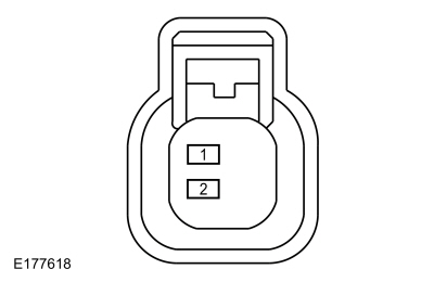 Liftgate release switch, pin 1
The Exterior Sounder Is Inoperative
Refer to Wiring Diagrams Cell 117 for schematic and connector information.
Normal Operations and Fault Conditions
REFER to: Handles, Locks, Latches and Entry Systems - System
Operation and Component Description (501-14 Handles, Locks, Latches and
Entry Systems, Description and Operation).
BCM DTC Fault Trigger Conditions
| DTC | Description | Fault Trigger Conditions |
|---|---|---|
| B14B8:11 | Sounder: Circuit Short To Ground | Sets when the BCM detects a short to ground from the exterior sounder voltage supply circuit. |
| B14B8:15 | Sounder: Circuit Short To Battery or Open | Sets when the BCM detects an open from the exterior sounder voltage supply circuit. |
Possible Cause
- Wiring, terminals or connectors
- Exterior sounder
- BCM
PINPOINT TEST R: THE EXTERIOR SOUNDER IS INOPERATIVE
| R1 CHECK THE BCM (BODY CONTROL MODULE) EXTERIOR SOUNDER OUTPUT | ||||||||||
|
NOTICE: The following step uses a test lamp to simulate normal circuit loads. Use only a Rotunda Test Lamp (SGT27000) or 250-300mA incandescent bulb test lamp. To avoid connector terminal damage, use the Rotunda Flex Probe kit for the test lamp probe connection to the vehicle. Do not use the test lamp probe directly on any connector.
Does the test lamp momentarily illuminate?
|
||||||||||
| R2 CHECK THE EXTERIOR SOUNDER GROUND CIRCUIT FOR AN OPEN | ||||||||||
|
NOTICE: The following step uses a test lamp to simulate normal circuit loads. Use only a Rotunda Test Lamp (SGT27000) or 250-300mA incandescent bulb test lamp. To avoid connector terminal damage, use the Rotunda Flex Probe kit for the test lamp probe connection to the vehicle. Do not use the test lamp probe directly on any connector.
Does the test lamp momentarily illuminate?
|
||||||||||
| R3 CHECK THE EXTERIOR SOUNDER VOLTAGE SUPPLY CIRCUIT FOR A SHORT TO GROUND | ||||||||||
Is the resistance greater than 10,000 ohms?
|
||||||||||
| R4 CHECK THE EXTERIOR SOUNDER VOLTAGE SUPPLY CIRCUIT FOR AN OPEN | ||||||||||
Is the resistance less than 3 ohms?
|
||||||||||
| R5 CHECK FOR CORRECT BCM (BODY CONTROL MODULE) OPERATION | ||||||||||
Is the concern still present?
|
The Exterior Sounder Chimes Continuously
Refer to Wiring Diagrams Cell 117 for schematic and connector information.
Normal Operations and Fault Conditions
REFER to: Handles, Locks, Latches and Entry Systems - System
Operation and Component Description (501-14 Handles, Locks, Latches and
Entry Systems, Description and Operation).
BCM DTC Fault Trigger Conditions
| DTC | Description | Fault Trigger Conditions |
|---|---|---|
| B14B8:15 | Sounder: Circuit Short To Battery or Open | Sets when the BCM detects a short to voltage from the exterior sounder voltage supply circuit. |
Possible Cause
- Wiring, terminals or connectors
- BCM
PINPOINT TEST S: THE EXTERIOR SOUNDER CHIMES CONTINUOUSLY
| S1 CHECK THE EXTERIOR SOUNDER VOLTAGE SUPPLY CIRCUIT FOR A SHORT TO VOLTAGE | ||||
Does the exterior sounder continue to chime?
|
||||
| S2 CHECK FOR CORRECT BCM (BODY CONTROL MODULE) OPERATION | ||||
Is the concern still present?
|
The Doors Do Not Lock Or Unlock Using The Keyless Entry Keypad
Refer to Wiring Diagrams Cell 117 for schematic and connector information.
Normal Operations and Fault Conditions
REFER to: Handles, Locks, Latches and Entry Systems - System
Operation and Component Description (501-14 Handles, Locks, Latches and
Entry Systems, Description and Operation).
BCM DTC Fault Trigger Conditions
| DTC | Description | Fault Trigger Conditions |
|---|---|---|
| B121B:01 | Keypad Input Switch: General Electrical Failure | Sets when the BCM detects a short to ground from any of the keyless entry keypad input circuits. |
Possible Causes
- Fuse
- Wiring, terminals or connectors
- Keyless entry keypad
- BCM
Visual Inspection and Diagnostic Pre-checks
- Inspect the front door window moulding for damage.
- Check the BCM fuse 10 (5A) and make sure it is OK.
PINPOINT TEST T: THE DOORS DO NOT LOCK OR UNLOCK USING THE KEYLESS ENTRY KEYPAD
| T1 CHECK POWER LOCK OPERATION FROM THE DOOR LOCK CONTROL SWITCH | ||||||||||||||||||||||
Do the doors lock and unlock?
|
||||||||||||||||||||||
| T2 CHECK THE KEYLESS ENTRY KEYPAD ILLUMINATION | ||||||||||||||||||||||
Do the keypad numbers illuminate?
|
||||||||||||||||||||||
| T3 CHECK THE KEYLESS ENTRY KEYPAD INDICATOR | ||||||||||||||||||||||
Does the round indicator on the top of the keypad illuminate?
|
||||||||||||||||||||||
| T4 CHECK THE KEYLESS ENTRY KEYPAD VOLTAGE SUPPLY CIRCUIT FOR VOLTAGE | ||||||||||||||||||||||
Is the voltage greater than 11 volts?
|
||||||||||||||||||||||
| T5 CHECK THE KEYLESS ENTRY KEYPAD VOLTAGE SUPPLY CIRCUIT FOR AN OPEN | ||||||||||||||||||||||
Is the resistance less than 3 ohms?
|
||||||||||||||||||||||
| T6 CHECK THE KEYLESS ENTRY KEYPAD GROUND CIRCUIT FOR AN OPEN | ||||||||||||||||||||||
Is the voltage greater than 11 volts?
|
||||||||||||||||||||||
| T7 CHECK FOR BCM (BODY CONTROL MODULE) DTC (DIAGNOSTIC TROUBLE CODE) B121B:01 | ||||||||||||||||||||||
Is DTC B121B:01 present?
|
||||||||||||||||||||||
| T8 ISOLATE THE KEYLESS ENTRY KEYPAD | ||||||||||||||||||||||
Is DTC B121B:01 still present?
|
||||||||||||||||||||||
| T9 CHECK THE KEYLESS ENTRY KEYPAD INPUT CIRCUITS FOR A SHORT TO GROUND | ||||||||||||||||||||||
Are the resistances greater than 10,000 ohms?
|
||||||||||||||||||||||
| T10 CHECK THE BCM (BODY CONTROL MODULE) KEYPAD BUTTON PARAMETER IDENTIFICATIONS (PIDS) | ||||||||||||||||||||||
Do the Parameter Identifications (PIDs) indicate the buttons operate correctly?
|
||||||||||||||||||||||
| T11 CHECK THE BCM (BODY CONTROL MODULE) KEYPAD CODE | ||||||||||||||||||||||
Do the doors unlock when the factory code is entered and lock when the 7/8 and 9/0 buttons are touched for 3 seconds?
|
||||||||||||||||||||||
| T12 CHECK THE KEYLESS ENTRY KEYPAD INPUT CIRCUITS USING THE BCM (BODY CONTROL MODULE) KEYPAD BUTTON PARAMETER IDENTIFICATIONS (PIDS) | ||||||||||||||||||||||
Do the Parameter Identifications (PIDs) correctly indicate Active with the fused jumper wire connected?
|
||||||||||||||||||||||
| T13 CHECK THE KEYLESS ENTRY KEYPAD INPUT CIRCUITS FOR A SHORT TO EACH OTHER | ||||||||||||||||||||||
Are the resistances greater than 10,000 ohms?
|
||||||||||||||||||||||
| T14 CHECK THE KEYLESS ENTRY KEYPAD INPUT CIRCUITS FOR AN OPEN | ||||||||||||||||||||||
Are the resistances less than 3 ohms?
|
||||||||||||||||||||||
| T15 CHECK FOR CORRECT BCM (BODY CONTROL MODULE) OPERATION | ||||||||||||||||||||||
Is the concern still present?
|
The Keyless Entry Keypad Illumination Is Inoperative
Refer to Wiring Diagrams Cell 117 for schematic and connector information.
Normal Operations and Fault Conditions
REFER to: Handles, Locks, Latches and Entry Systems - System
Operation and Component Description (501-14 Handles, Locks, Latches and
Entry Systems, Description and Operation).
BCM DTC Fault Trigger Conditions
| DTC | Description | Fault Trigger Conditions |
|---|---|---|
| B121A:11 | Keypad Illumination Output: Circuit Short To Ground | Sets when the BCM detects a short to ground from the keyless entry keypad illumination output circuit. |
| B121A:15 | Keypad Illumination Output: Circuit Short To Battery Or Open | Sets when the BCM detects an open from the keyless entry keypad illumination output circuit. |
Possible Causes
- Wiring, terminals or connectors
- Keyless entry keypad
- BCM
Visual Inspection and Diagnostic Pre-checks
- Inspect the front door window moulding for damage.
PINPOINT TEST U: THE KEYLESS ENTRY KEYPAD ILLUMINATION IS INOPERATIVE
| U1 CHECK THE KEYLESS ENTRY KEYPAD OPERATION | ||||||||||
Do the doors lock using the keyless entry keypad?
|
||||||||||
| U2 CHECK FOR BCM (BODY CONTROL MODULE) DTC (DIAGNOSTIC TROUBLE CODE) B121A:11 | ||||||||||
Is DTC B121A:11 present?
|
||||||||||
| U3 CHECK THE KEYLESS ENTRY KEYPAD FOR A SHORT TO GROUND | ||||||||||
Is DTC B121A:11 still present?
|
||||||||||
| U4 CHECK THE KEYPAD ILLUMINATION OUTPUT CIRCUIT FOR A SHORT TO GROUND | ||||||||||
Is the resistance greater than 10,000 ohms?
|
||||||||||
| U5 CHECK THE BCM (BODY CONTROL MODULE) OUTPUT USING THE KEYPAD LAMP OUTPUT STATUS (KEY_PAD_LMP) PID (PARAMETER IDENTIFICATION) | ||||||||||
Is the voltage greater than 11 volts?
|
||||||||||
| U6 CHECK THE BCM (BODY CONTROL MODULE) KEYPAD ILLUMINATION OUTPUT CIRCUIT FOR AN OPEN | ||||||||||
Is the resistance less than 3 ohms?
|
||||||||||
| U7 CHECK FOR CORRECT BCM (BODY CONTROL MODULE) OPERATION | ||||||||||
Is the concern still present?
|
The Keyless Entry Keypad Illumination Is Always On
Refer to Wiring Diagrams Cell 117 for schematic and connector information.
Normal Operations and Fault Conditions
REFER to: Handles, Locks, Latches and Entry Systems - System
Operation and Component Description (501-14 Handles, Locks, Latches and
Entry Systems, Description and Operation).
BCM DTC Fault Trigger Conditions
| DTC | Description | Fault Trigger Conditions |
|---|---|---|
| B121A:15 | Keypad Illumination Output: Circuit Short To Battery Or Open | Sets when the BCM detects a short to voltage from the keyless entry keypad illumination output circuit. |
Possible Causes
- Wiring, terminals or connectors
- Keyless entry keypad
- BCM
Visual Inspection and Diagnostic Pre-checks
- Inspect the front door window moulding for damage.
PINPOINT TEST V: THE KEYLESS ENTRY KEYPAD ILLUMINATION IS ALWAYS ON
| V1 CHECK THE KEYLESS ENTRY KEYPAD ILLUMINATION | ||||||||||
|
NOTE: It is normal operation for the keypad to illuminate when the illuminated entry/exit feature is active. Make sure all the doors are closed and the feature times out.
Is the keyless entry keypad illumination always on?
|
||||||||||
| V2 ISOLATE THE BCM (BODY CONTROL MODULE) | ||||||||||
Does the keypad continue illuminate?
|
||||||||||
| V3 CHECK THE BCM (BODY CONTROL MODULE) KEYPAD ILLUMINATION OUTPUT CIRCUIT FOR A SHORT TO VOLTAGE | ||||||||||
Is any voltage present?
|
||||||||||
| V4 CHECK FOR CORRECT BCM (BODY CONTROL MODULE) OPERATION | ||||||||||
Is the concern still present?
|
The RKE Transmitter Is Inoperative
Normal Operations and Fault Conditions
REFER to: Handles, Locks, Latches and Entry Systems - System
Operation and Component Description (501-14 Handles, Locks, Latches and
Entry Systems, Description and Operation).
BCM DTC Fault Trigger Conditions
| DTC | Description | Fault Trigger Conditions |
|---|---|---|
| B10AB:00 | Remote Keyless Entry Synchronization: No Sub Type Information | Sets when the BCM detects the rolling counter received from a RKE transmitter is out of synchronization with the rolling counter stored in the module. |
| B1218:00 | Transmitter Identification Code: No Sub Type Information | Sets when the BCM detects and invalid Transmitter Identification Code (TIC). |
Possible Causes
- Key batteries
- Key
- Key button pressed a substantial amount of times while outside the range of the vehicle
- Key programming
- Network concern
Visual Inspection and Diagnostic Pre-checks
- Inspect the key for damage.
- Check for aftermarket keys.
PINPOINT TEST W: THE RKE (REMOTE KEYLESS ENTRY) TRANSMITTER IS INOPERATIVE
| NOTE: At least 2 valid programmed keys must be present to begin diagnosis of the RKE system. | ||||
| W1 CHECK FOR THE CORRECT KEYS | ||||
Are the correct keys present?
|
||||
| W2 CHECK IF THE KEYS START THE VEHICLE | ||||
Do both keys start the vehicle?
|
||||
| W3 CHECK FOR REDUCED RANGE | ||||
|
NOTE: Make sure the vehicle is in an open area with no other large metal objects near, such as other vehicles or steel buildings. NOTE: If the RKE functions when near the vehicle, but not at approximately 30m (98 ft), a poor range concern is present.
Does any key experience a poor range concern?
|
||||
| W4 CHECK THE RKE (REMOTE KEYLESS ENTRY) FUNCTIONALITY OF THE KEYS | ||||
Are all the RKE functions inoperative from both keys?
|
||||
| W5 CHECK THE RKE (REMOTE KEYLESS ENTRY) FUNCTIONALITY OF THE SUSPECT KEY | ||||
Does any RKE function operate?
|
||||
| W6 CHECK THE NO (TIC) OUT OF SYNC (TIC-NONE_OOS) PID (PARAMETER IDENTIFICATION) | ||||
Does the PID indicate On?
|
||||
| W7 RESYNCHRONIZE THE INOPERATIVE PASSIVE KEY | ||||
Does the suspect key operate correctly now?
|
||||
| W8 RESYNCHRONIZE THE INOPERATIVE KEY USING THE SECOND KEY | ||||
Does the suspect key operate correctly now?
|
||||
| W9 CHECK THE (RKE) REMOTE BATTERY LOW (RKE_BATT_LOW) PID (PARAMETER IDENTIFICATION) | ||||
Does the PID indicate Off?
|
||||
| W10 CHECK THE PASSIVE KEY BATTERIES | ||||
|
NOTE: Do not clean off any grease from the battery terminals on the back surface of the circuit board.
Are the voltages greater than 2.5 volts?
|
||||
| W11 PROGRAM THE SUSPECT KEY | ||||
Does the RKE functionality operate?
|
||||
| W12 CHECK FOR COMMUNICATION WITH THE BCM (BODY CONTROL MODULE) AND THE RTM (RADIO TRANSCEIVER MODULE) | ||||
Does the BCM and the RTM pass the network test?
|
||||
| W13 CHECK FOR RTM (RADIO TRANSCEIVER MODULE) DIAGNOSTIC TROUBLE CODES (DTCS) | ||||
Are any Diagnostic Trouble Codes (DTCs) present?
|
||||
| W14 CHECK FOR BCM (BODY CONTROL MODULE) DIAGNOSTIC TROUBLE CODES (DTCS) | ||||
Are any Diagnostic Trouble Codes (DTCs) present?
|
An Individual Button/Feature Is Inoperative From The RKE Transmitter
Normal Operations and Fault Conditions
REFER to: Handles, Locks, Latches and Entry Systems - System
Operation and Component Description (501-14 Handles, Locks, Latches and
Entry Systems, Description and Operation).
Possible Causes
- Door lock system concern
- Liftgate latch release system concern
- Power liftgate system concern
- Horn system concern
- Turn signal system concern
- Remote start system concern
- Key
Visual Inspection and Diagnostic Pre-checks
- Inspect the key for damage.
PINPOINT TEST X: AN INDIVIDUAL BUTTON/FEATURE IS INOPERATIVE FROM THE RKE (REMOTE KEYLESS ENTRY) TRANSMITTER
| X1 VERIFY THE DOOR LOCK OPERATION | ||||
Do the door locks operate?
|
||||
| X2 VERIFY THE HORN OPERATION USING THE BCM (BODY CONTROL MODULE) PID (PARAMETER IDENTIFICATION) (HORN_RELAY) | ||||
Does the horn sound when commanded on?
|
||||
| X3 VERIFY THE HAZARD LAMP OPERATION | ||||
Do the hazard lamps operate correctly?
|
||||
| X4 VERIFY THE LIFTGATE LATCH RELEASE OPERATION | ||||
Does the liftgate latch release (manual liftgate) or the liftgate power open (power liftgate)?
|
||||
| X5 CHECK THE LOCK AND UNLOCK BUTTONS | ||||
Do the doors lock and unlock?
|
||||
| X6 CHECK THE LIFTGATE RELEASE BUTTON | ||||
Does the liftgate latch release (manual liftgate) or the power open (power liftgate)?
|
||||
| X7 CHECK THE PANIC ALARM/VEHICLE LOCATOR BUTTON | ||||
Do the exterior lamps flash and the horn/chime sound?
|
||||
| X8 VERIFY THE REMOTE START OPERATION | ||||
Does the vehicle remotely start?
|
The RKE Transmitter Has Poor Range Performance
Normal Operations and Fault Conditions
REFER to: Handles, Locks, Latches and Entry Systems - System
Operation and Component Description (501-14 Handles, Locks, Latches and
Entry Systems, Description and Operation).
Possible Causes
- Key
- Key batteries
- Aftermarket system
- Consumer electronic device
- High power devices
- TV/radio transmission towers
- RTM
Visual Inspection and Diagnostic Pre-checks
- Inspect the key for damage.
- Inspect the key batteries.
- Inspect for aftermarket RKE systems.
PINPOINT TEST Y: THE RKE (REMOTE KEYLESS ENTRY) TRANSMITTER HAS POOR RANGE PERFORMANCE
| NOTE: At least 2 valid programmed keys must be present to begin diagnosis of the RKE system. | ||||
| Y1 CHECK FOR THE CORRECT KEYS | ||||
Are the correct keys present?
|
||||
| Y2 CHECK ALL KEYS FOR POOR RANGE PERFORMANCE | ||||
|
NOTE: Make sure the vehicle is in an open area with no other large metal objects near, such as other vehicles or steel buildings.
Do all keys experience poor range?
|
||||
| Y3 CHECK THE PASSIVE KEY BATTERIES | ||||
|
NOTE: Do not clean off any grease from the battery terminals on the back surface of the circuit board.
Are the voltages greater than 2.5 volts?
|
||||
| Y4 CHECK THE LOCATION OF THE VEHICLE AND THE APPROACH ANGLES AROUND THE VEHICLE | ||||
Is the poor range performance consistent around the vehicle?
|
The Remote Start Feature Is Inoperative
Refer to Wiring Diagrams Cell 13 for schematic and connector information.
Normal Operations and Fault Conditions
REFER to: Handles, Locks, Latches and Entry Systems - System
Operation and Component Description (501-14 Handles, Locks, Latches and
Entry Systems, Description and Operation).
Possible Causes
- Wiring, terminals or connectors
- Remote start feature not enabled
- Key
- Hood ajar switch input concern
- Door ajar switch input concern
- TR input concern
- Park detect switch input concern
- Powertrain concern
- BCM
Visual Inspection and Diagnostic Pre-checks
- Inspect the passive key for damage.
PINPOINT TEST Z: THE REMOTE START FEATURE IS INOPERATIVE
| NOTE: This pinpoint test does not diagnose dealer installed remote start systems. | ||||||||||||||||
| Z1 CHECK THE REMOTE START FEATURE ENABLE/DISABLE SETTING | ||||||||||||||||
Is the remote start feature enabled?
|
||||||||||||||||
| Z2 CHECK THE PARK DETECT SWITCH INPUT | ||||||||||||||||
Does the PRNDL display correctly?
|
||||||||||||||||
| Z3 CHECK FOR BCM (BODY CONTROL MODULE) DIAGNOSTIC TROUBLE CODES (DTCS) | ||||||||||||||||
Are any BCM Diagnostic Trouble Codes (DTCs) present?
|
||||||||||||||||
| Z4 CHECK FOR POWERTRAIN DIAGNOSTIC TROUBLE CODES (DTCS) | ||||||||||||||||
Are any PCM Diagnostic Trouble Codes (DTCs) present?
|
||||||||||||||||
| Z5 CHECK THE RKE (REMOTE KEYLESS ENTRY) FUNCTIONALITY | ||||||||||||||||
Do all the functions tested of the RKE transmitter operate (lock, unlock and liftgate latch release or power liftgate open)?
|
||||||||||||||||
| Z6 CHECK THE WAKE-UP CIRCUIT FOR VOLTAGE AT THE PCM (POWERTRAIN CONTROL MODULE) USING THE BCM (BODY CONTROL MODULE) PID (PARAMETER IDENTIFICATION) (PCM) WAKE-UP OUTPUT CONTROL (PCM_WKUP_CTRL) | ||||||||||||||||
Is the voltage greater than 11 volts?
|
||||||||||||||||
| Z7 CHECK THE WAKE-UP CIRCUIT FOR AN OPEN | ||||||||||||||||
Is the resistance less than 3 ohms?
|
||||||||||||||||
| Z8 VERIFY THE REMOTE START FUNCTION IS INOPERATIVE | ||||||||||||||||
Does the vehicle remotely start?
|
||||||||||||||||
| Z9 CHECK FOR CORRECT BCM (BODY CONTROL MODULE) OPERATION | ||||||||||||||||
Is the concern still present?
|
A Door Passive Entry Feature Is Inoperative
Refer to Wiring Diagrams Cell 117 for schematic and connector information.
Normal Operations and Fault Conditions
REFER to: Handles, Locks, Latches and Entry Systems - System
Operation and Component Description (501-14 Handles, Locks, Latches and
Entry Systems, Description and Operation).
BCM DTC Fault Trigger Conditions
| DTC | Description | Fault Trigger Conditions |
|---|---|---|
| B1336:01 | Driver Door External Antenna: General Electrical Failure | Sets when the BCM detects a fault from one of the circuits to the driver side keyless entry antenna (internal to the front driver exterior door handle). |
| B1337:01 | Passenger Door External Antenna: General Electrical Failure | Sets when the BCM detects a fault from one of the circuits to the passenger side keyless entry antenna (internal to the front passenger exterior door handle). |
| B1381:11 | Left Front Door Handle Proximity Sensor: Circuit Short To Ground | Sets when the BCM detects a fault from one of the circuits to the left front exterior door handle. |
| B1381:15 | Left Front Door Handle Proximity Sensor: Circuit Short To Battery or Open | Sets when the BCM detects a fault from one of the circuits to the left front exterior door handle. |
| B1381:29 | Left Front Door Handle Proximity Sensor: Signal Invalid | Sets when the BCM detects an activated touch sensor for more than 5 minutes. |
| B1382:11 | Right Front Door Handle Proximity Sensor: Circuit Short To Ground | Sets when the BCM detects a fault from one of the circuits to the right exterior door handle. |
| B1382:15 | Right Front Door Handle Proximity Sensor: Circuit Short To Battery or Open | Sets when the BCM detects a fault from one of the circuits to the right exterior door handle. |
| B1382:29 | Right Front Door Handle Proximity Sensor: Signal Invalid | Sets when the BCM detects an activated touch sensor for more than 5 minutes. |
| B1383:11 | Left Rear Door Handle Proximity Sensor: Circuit Short To Ground | Sets when the BCM detects a fault from one of the circuits to the left rear exterior door handle. |
| B1383:15 | Left Rear Door Handle Proximity Sensor: Circuit Short To Battery or Open | Sets when the BCM detects a fault from one of the circuits to the left rear exterior door handle. |
| B1383:29 | Left Rear Door Handle Proximity Sensor: Signal Invalid | Sets when the BCM detects an activated touch sensor for more than 5 minutes. |
| B1384:11 | Right Rear Door Handle Proximity Sensor: Circuit Short To Ground | Sets when the BCM detects a fault from one of the circuits to the right rear exterior door handle. |
| B1384:15 | Right Rear Door Handle Proximity Sensor: Circuit Short To Battery or Open | Sets when the BCM detects a fault from one of the circuits to the right rear exterior door handle. |
| B1384:29 | Right Rear Door Handle Proximity Sensor: Signal Invalid | Sets when the BCM detects an activated touch sensor for more than 5 minutes. |
Possible Causes
- Wiring, terminals or connectors
- Door lock system concern
- RKE system concern
- Exterior door handle
- BCM
Visual Inspection and Diagnostic Pre-checks
- Inspect the exterior door handles for damage.
PINPOINT TEST AA: A DOOR PASSIVE ENTRY FEATURE IS INOPERATIVE
| AA1 CHECK THE DOOR LOCK OPERATION | ||||||||||||||||||||||||||||||||||||||||||||||||||||
Do the doors lock and unlock?
|
||||||||||||||||||||||||||||||||||||||||||||||||||||
| AA2 CHECK THE RKE (REMOTE KEYLESS ENTRY) OPERATION | ||||||||||||||||||||||||||||||||||||||||||||||||||||
Do the doors lock and unlock?
|
||||||||||||||||||||||||||||||||||||||||||||||||||||
| AA3 CHECK THE PASSIVE ENTRY OPERATION FROM BOTH ALL DOORS | ||||||||||||||||||||||||||||||||||||||||||||||||||||
Is the passive entry feature inoperative from all doors?
|
||||||||||||||||||||||||||||||||||||||||||||||||||||
| AA4 CHECK THE EXTERIOR DOOR HANDLE GROUND CIRCUIT FOR A SHORT TO VOLTAGE | ||||||||||||||||||||||||||||||||||||||||||||||||||||
Is any voltage present?
|
||||||||||||||||||||||||||||||||||||||||||||||||||||
| AA5 CHECK THE EXTERIOR DOOR HANDLE GROUND CIRCUIT FOR A SHORT TO GROUND | ||||||||||||||||||||||||||||||||||||||||||||||||||||
Is the resistance greater than 10,000 ohms?
|
||||||||||||||||||||||||||||||||||||||||||||||||||||
| AA6 CHECK THE EXTERIOR DOOR HANDLE GROUND CIRCUIT FOR AN OPEN (ALL DOORS PASSIVE ENTRY INOPERATIVE) | ||||||||||||||||||||||||||||||||||||||||||||||||||||
Is the resistance less than 3 ohms?
|
||||||||||||||||||||||||||||||||||||||||||||||||||||
| AA7 CHECK FOR VOLTAGE TO THE EXTERIOR DOOR HANDLE | ||||||||||||||||||||||||||||||||||||||||||||||||||||
Is the voltage greater than 11 volts?
|
||||||||||||||||||||||||||||||||||||||||||||||||||||
| AA8 CHECK THE EXTERIOR DOOR HANDLE VOLTAGE SUPPLY CIRCUIT FOR A SHORT TO GROUND | ||||||||||||||||||||||||||||||||||||||||||||||||||||
Is the resistance greater than 10,000 ohms?
|
||||||||||||||||||||||||||||||||||||||||||||||||||||
| AA9 CHECK THE EXTERIOR DOOR HANDLE VOLTAGE SUPPLY CIRCUIT FOR AN OPEN | ||||||||||||||||||||||||||||||||||||||||||||||||||||
Is the resistance less than 3 ohms?
|
||||||||||||||||||||||||||||||||||||||||||||||||||||
| AA10 CHECK THE EXTERIOR DOOR HANDLE GROUND CIRCUIT FOR AN OPEN | ||||||||||||||||||||||||||||||||||||||||||||||||||||
Is the resistance less than 3 ohms?
|
||||||||||||||||||||||||||||||||||||||||||||||||||||
| AA11 CHECK THE EXTERIOR DOOR HANDLE INTERNAL ANTENNA | ||||||||||||||||||||||||||||||||||||||||||||||||||||
Is the resistance between 1 and 3 ohms?
|
||||||||||||||||||||||||||||||||||||||||||||||||||||
| AA12 CHECK THE EXTERIOR DOOR HANDLE | ||||||||||||||||||||||||||||||||||||||||||||||||||||
Does the keyless entry feature operate from the suspect door?
|
||||||||||||||||||||||||||||||||||||||||||||||||||||
| AA13 CHECK THE EXTERIOR DOOR HANDLE ANTENNA CIRCUITS FOR A SHORT TO VOLTAGE | ||||||||||||||||||||||||||||||||||||||||||||||||||||
Is any voltage present?
|
||||||||||||||||||||||||||||||||||||||||||||||||||||
| AA14 CHECK THE EXTERIOR DOOR HANDLE ANTENNA CIRCUITS FOR A SHORT TO GROUND | ||||||||||||||||||||||||||||||||||||||||||||||||||||
Are the resistances greater than 10,000 ohms?
|
||||||||||||||||||||||||||||||||||||||||||||||||||||
| AA15 CHECK THE EXTERIOR DOOR HANDLE ANTENNA CIRCUITS FOR AN OPEN | ||||||||||||||||||||||||||||||||||||||||||||||||||||
Are the resistances less than 3 ohms?
|
||||||||||||||||||||||||||||||||||||||||||||||||||||
| AA16 CHECK FOR CORRECT BCM (BODY CONTROL MODULE) OPERATION | ||||||||||||||||||||||||||||||||||||||||||||||||||||
Is the concern still present?
|
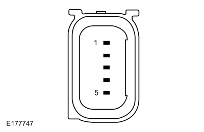 C543, pin 2, component side
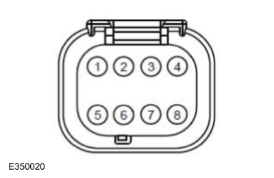 C573, pin 6, component side
The Liftgate Passive Entry Feature Is Inoperative
Refer to Wiring Diagrams Cell 117 for schematic and connector information.
Normal Operations and Fault Conditions
REFER to: Handles, Locks, Latches and Entry Systems - System
Operation and Component Description (501-14 Handles, Locks, Latches and
Entry Systems, Description and Operation).
BCM DTC Fault Trigger Conditions
| DTC | Description | Fault Trigger Conditions |
|---|---|---|
| B10C7:01 | Interior Trunk Antenna: General Electrical Failure | Sets when the BCM detects a fault from the keyless entry rear antenna input. |
Possible Causes
- Wiring, terminals or connectors
- Keyless entry rear antenna
- BCM
PINPOINT TEST AB: THE LIFTGATE PASSIVE ENTRY FEATURE IS INOPERATIVE
| AB1 CHECK THE RKE (REMOTE KEYLESS ENTRY) OPERATION | |||||||||||||
Does the liftgate latch release (manual liftgate) or the liftgate power open (power liftgate)?
|
|||||||||||||
| AB2 CHECK THE LIFTGATE RELEASE SWITCH INPUT | |||||||||||||
Does the liftgate latch release (manual liftgate) or power open (power liftgate)?
|
|||||||||||||
| AB3 CHECK THE BCM (BODY CONTROL MODULE) LIFTGATE RELEASE SWITCH STATUS (LFTGATE_R_SW) PID (PARAMETER IDENTIFICATION) | |||||||||||||
Does the PID indicate the switch is pressed?
|
|||||||||||||
| AB4 CHECK THE LIFTGATE RELEASE SWITCH INPUT CIRCUIT FOR AN OPEN | |||||||||||||
Is the resistance less than 3 ohms?
|
|||||||||||||
| AB5 CHECK THE KEYLESS ENTRY REAR ANTENNA | |||||||||||||
Is the resistance between 1 and 3 ohms?
|
|||||||||||||
| AB6 CHECK THE KEYLESS ENTRY REAR ANTENNA CIRCUITS FOR A SHORT TO VOLTAGE | |||||||||||||
Is any voltage present?
|
|||||||||||||
| AB7 CHECK THE KEYLESS ENTRY REAR ANTENNA CIRCUITS FOR A SHORT TO GROUND | |||||||||||||
Are the resistances greater than 10,000 ohms?
|
|||||||||||||
| AB8 CHECK THE KEYLESS ENTRY REAR ANTENNA CIRCUITS FOR AN OPEN | |||||||||||||
Are the resistances less than 3 ohms?
|
|||||||||||||
| AB9 CHECK FOR CORRECT BCM (BODY CONTROL MODULE) OPERATION | |||||||||||||
Is the concern still present?
|
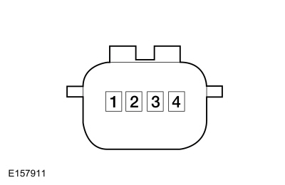 C4321, pin 1, component side
The Approach Detection Feature Is Inoperative
Normal Operations and Fault Conditions
REFER to: Handles, Locks, Latches and Entry Systems - System
Operation and Component Description (501-14 Handles, Locks, Latches and
Entry Systems, Description and Operation).
Possible Cause
- Approach detection disabled
- Passive entry system concern
- Illuminated entry concern
- RKE system concern
PINPOINT TEST AC: THE APPROACH DETECTION FEATURE IS INOPERATIVE
| AC1 CHECK THE APPROACH DETECTION SETTING | ||||
Is the approach detection setting enabled?
|
||||
| AC2 CHECK THE PASSIVE ENTRY FEATURE | ||||
Does the passive entry feature operate from the front doors and the liftgate?
|
||||
| AC3 CHECK THE ILLUMINATED ENTRY OPERATION | ||||
Does the illuminated entry feature operate correctly?
|
U0146:00
Normal Operations and Fault Conditions
The RTM communicates with the GWM over the CAN . If the RTM does not receive messages from the GWM , features such as the passive entry can be inoperative.
RTM DTC Fault Trigger Conditions
| DTC | Description | Fault Trigger Conditions |
|---|---|---|
| U0146:00 | Lost Communication With Gateway "A": No Sub Type Information | Sets when the RTM detects data messages are missing from the GWM over the CAN . |
Possible Causes
- Network communication concern
- GWM
PINPOINT TEST AD: U0146:00
| AD1 VERIFY THE CUSTOMER CONCERN | ||||
Is an observable symptom present?
|
||||
| AD2 CHECK THE COMMUNICATION NETWORK | ||||
Does the GWM pass the network test?
|
||||
| AD3 CHECK FOR NON-NETWORK GWM (GATEWAY MODULE A) DIAGNOSTIC TROUBLE CODES (DTCS) | ||||
Are any non-network Diagnostic Trouble Codes (DTCs) present?
|
||||
| AD4 CHECK FOR NON-NETWORK RTM (RADIO TRANSCEIVER MODULE) DIAGNOSTIC TROUBLE CODES (DTCS) | ||||
Are any non-network Diagnostic Trouble Codes (DTCs) present?
|
||||
| AD5 RECHECK THE RTM (RADIO TRANSCEIVER MODULE) DIAGNOSTIC TROUBLE CODES (DTCS) | ||||
Is DTC U0146:00 still present?
|
||||
| AD6 CHECK FOR OTHER CAUSES OF COMMUNICATION NETWORK CONCERN | ||||
|
NOTE: If new modules were installed prior to the DTC being set, the module configuration may be incorrectly set during PMI or the PMI may not have been carried out.
Is the observable symptom still present?
|
||||
| AD7 CHECK FOR CORRECT GWM (GATEWAY MODULE A) OPERATION | ||||
Is the concern still present?
|
U0258:87 or U1A00:00
Refer to Wiring Diagrams Cell 117 for schematic and connector information.
Normal Operation and Fault Conditions
The RTM communicates with the BCM over a LIN -based circuit and, when the network is awake, over the CAN .
RTM DTC Fault Trigger Conditions
| DTC | Description | Fault Trigger Conditions |
|---|---|---|
| U1A00:00 | Private Communication Network: No Sub Type Information | Sets when the RTM detects a fault with the LIN -based circuit to the BCM . |
BCM DTC Fault Trigger Conditions
| DTC | Description | Fault Trigger Conditions |
|---|---|---|
| U0258:87 | Lost Communication With Radio Transceiver: Missing Message | Sets when the BCM detects a communication fault with the RTM over the LIN -based circuit. |
Possible Causes
- Wiring, terminals or connectors
- RTM
- BCM
PINPOINT TEST AE: U0258:87 OR U1A00:00
| AE1 CHECK IF THE RTM (RADIO TRANSCEIVER MODULE) AND THE BCM (BODY CONTROL MODULE) PASS THE NETWORK TEST | ||||||||||
Does the RTM and the BCM pass the network test?
|
||||||||||
| AE2 CHECK THE LIN (LOCAL INTERCONNECT NETWORK) CIRCUIT FOR A SHORT TO VOLTAGE | ||||||||||
|
NOTE: It is necessary to place the passive key in the backup starting location to transition the ignition on. Refer to the Description and Operation in section 419-01B.
Is any voltage present?
|
||||||||||
| AE3 CHECK THE LIN (LOCAL INTERCONNECT NETWORK) CIRCUIT FOR A SHORT TO GROUND | ||||||||||
Is the resistance greater than 10,000 ohms?
|
||||||||||
| AE4 CHECK THE LIN (LOCAL INTERCONNECT NETWORK) CIRCUIT FOR AN OPEN | ||||||||||
Is the resistance less than 3 ohms?
|
||||||||||
| AE5 CHECK FOR CORRECT RTM (RADIO TRANSCEIVER MODULE) OPERATION | ||||||||||
Is the concern still present?
|
||||||||||
| AE6 CHECK FOR CORRECT BCM (BODY CONTROL MODULE) OPERATION | ||||||||||
Is the concern still present?
|
B1087:83 or B1087:87
Refer to Wiring Diagrams Cell 117 for schematic and connector information.
Normal Operation and Fault Conditions
The DDM communicates with the left RDM over a LIN circuit. In the event the left RDM fails, the left rear power window and power door lock become inoperative.
The PDM communicates with the right RDM over a LIN circuit. In the event the right RDM fails, the right rear power window and power door lock become inoperative.
DDM / PDM DTC Fault Trigger Conditions
| DTC | Description | Fault Trigger Conditions |
|---|---|---|
| B1087:83 | LIN Bus "A": Value Of Signal Protection Calculation Incorrect | Sets when the DDM / PDM detects a fault with the communication from the corresponding RDM . |
| B1087:87 | LIN Bus "A": Signal Invalid | Sets when the DDM / PDM detects a fault with the communication from the corresponding RDM . |
Possible Cause
- Fuse
- Wiring, terminals or connectors
- RDM
- BCM
Visual Inspection and Diagnostic Pre-checks
- Inspect the BCM fuse 29 (30A) (left RDM ) and make sure it is OK.
- Inspect the BCM fuse 30 (30A) (right RDM ) and make sure it is OK.
PINPOINT TEST AF: B1087:83 OR B1087:87
| AF1 CHECK IF THE DTC (DIAGNOSTIC TROUBLE CODE) SET IN THE DDM (DRIVER DOOR MODULE) | ||||||||||||||||
Is DTC B1087:83 or B1087:87 set in the DDM ?
|
||||||||||||||||
| AF2 ISOLATE THE WINDOW CONTROL SWITCH | ||||||||||||||||
Is DTC B1087:83 or B1087:87 still present?
|
||||||||||||||||
| AF3 CHECK FOR VOLTAGE TO THE RDM (REAR DOOR MODULE) | ||||||||||||||||
Is the voltage greater than 11 volts?
|
||||||||||||||||
| AF4 CHECK THE REAR DOOR MODULE VOLTAGE SUPPLY CIRCUIT FOR AN OPEN | ||||||||||||||||
Is the resistance less than 3 ohms?
|
||||||||||||||||
| AF5 CHECK THE REAR DOOR MODULE GROUND CIRCUIT FOR AN OPEN | ||||||||||||||||
Is the voltage greater than 11 volts?
|
||||||||||||||||
| AF6 CHECK THE LIN (LOCAL INTERCONNECT NETWORK) CIRCUIT FOR A SHORT TO VOLTAGE | ||||||||||||||||
Is any voltage present?
|
||||||||||||||||
| AF7 CHECK THE LIN (LOCAL INTERCONNECT NETWORK) CIRCUIT FOR A SHORT TO GROUND | ||||||||||||||||
Is the resistance greater than 10,000 ohms?
|
||||||||||||||||
| AF8 CHECK THE CHECK THE LIN (LOCAL INTERCONNECT NETWORK) CIRCUIT FOR AN OPEN | ||||||||||||||||
Is the resistance less than 3 ohms?
|
||||||||||||||||
| AF9 CHECK FOR CORRECT RDM (REAR DOOR MODULE) OPERATION | ||||||||||||||||
Is the concern still present?
|
||||||||||||||||
| AF10 CHECK FOR CORRECT FRONT DOOR MODULE OPERATION | ||||||||||||||||
Is the concern still present?
|
||||||||||||||||
| AF11 CHECK FOR CORRECT BCM (BODY CONTROL MODULE) OPERATION | ||||||||||||||||
Is the concern still present?
|
U0140:00
Normal Operation and Fault Conditions
The DDM / PDM communicates with the BCM over the CAN . If the DDM / PDM does not receive messages from the BCM , features such as the puddle lamps, exterior mirror turn signal and door switch illumination can be inoperative.
DDM / PDM DTC Fault Trigger Conditions
| DTC | Description | Fault Trigger Conditions |
|---|---|---|
| U0140:00 | Lost Communication With Body Control Module: No Sub-Type Information | Sets when the DDM / PDM detects data messages are missing from the BCM . |
Possible Causes
- Network communication concern
- BCM
PINPOINT TEST AG: U0140:00
| AG1 VERIFY THE CUSTOMER CONCERN | ||||
Is an observable symptom present?
|
||||
| AG2 CHECK THE COMMUNICATION NETWORK | ||||
Does the BCM pass the network test?
|
||||
| AG3 CHECK FOR NON-NETWORK BCM (BODY CONTROL MODULE) DIAGNOSTIC TROUBLE CODES (DTCS) | ||||
Are any non-network Diagnostic Trouble Codes (DTCs) present?
|
||||
| AG4 CHECK FOR NON-NETWORK DDM (DRIVER DOOR MODULE) OR PDM (PASSENGER DOOR MODULE) DIAGNOSTIC TROUBLE CODES (DTCS) | ||||
Are any non-network Diagnostic Trouble Codes (DTCs) present?
|
||||
| AG5 RECHECK THE DDM (DRIVER DOOR MODULE) OR PDM (PASSENGER DOOR MODULE) DIAGNOSTIC TROUBLE CODES (DTCS) | ||||
Is DTC U0140:00 still present?
|
||||
| AG6 CHECK FOR OTHER CAUSES OF COMMUNICATION NETWORK CONCERN | ||||
|
NOTE: If new modules were installed prior to the DTC being set, the module configuration may be incorrectly set during PMI or the PMI may not have been carried out.
Is the observable symptom still present?
|
||||
| AG7 CHECK FOR CORRECT BCM (BODY CONTROL MODULE) OPERATION | ||||
Is the concern still present?
|
U0208:00
Normal Operation and Fault Conditions
The DDM / PDM communicate with the DSM over the CAN . If the DDM / PDM does not receive messages from the DSM , features such as the memory mirror position can be inoperative.
DDM / PDM DTC Fault Trigger Conditions
| DTC | Description | Fault Trigger Conditions |
|---|---|---|
| U0208:00 | Lost Communication With "Seat Control Module A": No Sub-Type Information | Sets when the DDM / PDM detects data messages are missing from the DSM . |
Possible Causes
- Network communication concern
- DSM
PINPOINT TEST AH: U0208:00
| AH1 VERIFY THE CUSTOMER CONCERN | ||||
Is an observable symptom present?
|
||||
| AH2 CHECK THE COMMUNICATION NETWORK | ||||
Does the DSM pass the network test?
|
||||
| AH3 CHECK FOR NON-NETWORK DSM (DRIVER FRONT SEAT MODULE) DIAGNOSTIC TROUBLE CODES (DTCS) | ||||
Are any non-network Diagnostic Trouble Codes (DTCs) present?
|
||||
| AH4 CHECK FOR NON-NETWORK DDM (DRIVER DOOR MODULE) OR PDM (PASSENGER DOOR MODULE) DIAGNOSTIC TROUBLE CODES (DTCS) | ||||
Are any non-network Diagnostic Trouble Codes (DTCs) present?
|
||||
| AH5 RECHECK THE DDM (DRIVER DOOR MODULE) OR PDM (PASSENGER DOOR MODULE) DIAGNOSTIC TROUBLE CODES (DTCS) | ||||
Is DTC U0208:00 still present?
|
||||
| AH6 CHECK FOR OTHER CAUSES OF COMMUNICATION NETWORK CONCERN | ||||
|
NOTE: If new modules were installed prior to the DTC being set, the module configuration may be incorrectly set during PMI or the PMI may not have been carried out.
Is the observable symptom still present?
|
||||
| AH7 CHECK FOR CORRECT DSM (DRIVER FRONT SEAT MODULE) OPERATION | ||||
Is the concern still present?
|
U0232:00
Normal Operation and Fault Conditions
The DDM communicates with the SODL over the CAN . If the DDM does not receive messages from the SODL , the side obstacle detection feature can be inoperative for the left side.
DDM DTC Fault Trigger Conditions
| DTC | Description | Fault Trigger Conditions |
|---|---|---|
| U0232:00 | Lost Communication With Side Obstacle Detection Control Module - Left: No Sub-Type Information | Sets when the DDM detects data messages are missing from the SODL . |
Possible Causes
- Network communication concern
- SODL
PINPOINT TEST AI: U0232:00
| AI1 VERIFY THE CUSTOMER CONCERN | ||||
Is an observable symptom present?
|
||||
| AI2 CHECK THE COMMUNICATION NETWORK | ||||
Does the SODL pass the network test?
|
||||
| AI3 CHECK FOR NON-NETWORK SODL (SIDE OBSTACLE DETECTION CONTROL MODULE LH) DIAGNOSTIC TROUBLE CODES (DTCS) | ||||
Are any non-network Diagnostic Trouble Codes (DTCs) present?
|
||||
| AI4 CHECK FOR NON-NETWORK DDM (DRIVER DOOR MODULE) DIAGNOSTIC TROUBLE CODES (DTCS) | ||||
Are any non-network Diagnostic Trouble Codes (DTCs) present?
|
||||
| AI5 RECHECK THE DDM (DRIVER DOOR MODULE) DIAGNOSTIC TROUBLE CODES (DTCS) | ||||
Is DTC U0232:00 still present?
|
||||
| AI6 CHECK FOR OTHER CAUSES OF COMMUNICATION NETWORK CONCERN | ||||
|
NOTE: If new modules were installed prior to the DTC being set, the module configuration may be incorrectly set during PMI or the PMI may not have been carried out.
Is the observable symptom still present?
|
||||
| AI7 CHECK FOR CORRECT SODL (SIDE OBSTACLE DETECTION CONTROL MODULE LH) OPERATION | ||||
Is the concern still present?
|
U0233:00
Normal Operation and Fault Conditions
The PDM communicates with the SODR over the CAN . If the PDM does not receive messages from the SODR , the side obstacle detection feature can be inoperative for the right side.
PDM DTC Fault Trigger Conditions
| DTC | Description | Fault Trigger Conditions |
|---|---|---|
| U0233:00 | Lost Communication With Side Obstacle Detection Control Module - Right: No Sub-Type Information | Sets when the PDM detects data messages are missing from the SODR . |
Possible Causes
- Network communication concern
- SODR
PINPOINT TEST AJ: U0233:00
| AJ1 VERIFY THE CUSTOMER CONCERN | ||||
Is an observable symptom present?
|
||||
| AJ2 CHECK THE COMMUNICATION NETWORK | ||||
Does the SODR pass the network test?
|
||||
| AJ3 CHECK FOR NON-NETWORK SODR (SIDE OBSTACLE DETECTION CONTROL MODULE RH) DIAGNOSTIC TROUBLE CODES (DTCS) | ||||
Are any non-network Diagnostic Trouble Codes (DTCs) present?
|
||||
| AJ4 CHECK FOR NON-NETWORK PDM (PASSENGER DOOR MODULE) DIAGNOSTIC TROUBLE CODES (DTCS) | ||||
Are any non-network Diagnostic Trouble Codes (DTCs) present?
|
||||
| AJ5 RECHECK THE PDM (PASSENGER DOOR MODULE) DIAGNOSTIC TROUBLE CODES (DTCS) | ||||
Is DTC U0233:00 still present?
|
||||
| AJ6 CHECK FOR OTHER CAUSES OF COMMUNICATION NETWORK CONCERN | ||||
|
NOTE: If new modules were installed prior to the DTC being set, the module configuration may be incorrectly set during PMI or the PMI may not have been carried out.
Is the observable symptom still present?
|
||||
| AJ7 CHECK FOR CORRECT SODR (SIDE OBSTACLE DETECTION CONTROL MODULE RH) OPERATION | ||||
Is the concern still present?
|
P1594 OR P1595
Normal Operation and Fault Conditions
When the BCM receives a request to remote start the vehicle, it first checks to make sure conditions exist to allow it to start (for example, the hood and doors closed, vehicle in PARK, no powertrain concerns). If the required conditions are correct, the BCM starts the vehicle and allows it to run for a predetermined amount of time, determined by the setting selected from the message center.
PCM DTC Fault Trigger Conditions
| DTC | Description | Fault Trigger Conditions |
|---|---|---|
| P1594 | Forced Engine Shutdown - Remote Start System Fault, No Unattended Vehicle Timeout | Sets when the PCM detects the remote start has been active for more than 30 minutes continuously. |
| P1595 | Forced Engine Shutdown - Remote Start System Fault, Transmission Range Not In Park Position | Sets when the PCM detects the remote start is active with the transmission not in PARK. |
Possible Causes
- Network communication concern
- Powertrain concern
PINPOINT TEST AK: P1594 OR P1595
| AK1 CHECK FOR OTHER PCM (POWERTRAIN CONTROL MODULE) DIAGNOSTIC TROUBLE CODES (DTCS) | ||||
Are any other PCM Diagnostic Trouble Codes (DTCs) present?
|
||||
| AK2 CHECK FOR BCM (BODY CONTROL MODULE) DIAGNOSTIC TROUBLE CODES (DTCS) | ||||
Are any BCM Diagnostic Trouble Codes (DTCs) present?
|
B11DA:23
Normal Operation and Fault Conditions
The DDM sends voltage signals to the door latch to monitor the door lock cylinder lock/unlock position.
DDM DTC Fault Trigger Conditions
| DTC | Description | Fault Trigger Conditions |
|---|---|---|
| B11DA:23 | Driver Door Key Cylinder Switch: Signal Stuck Low | Sets when the DDM detects a short to ground from one of the door lock cylinder input circuits. |
Possible Causes
- Wiring, terminals or connectors
- Door latch
- DDM
PINPOINT TEST AL: B11DA:23
| AL1 CHECK THE OPERATION OF THE DOOR LOCK CYLINDER | |||||||||||||
Does the door lock cylinder lock and unlock the door?
|
|||||||||||||
| AL2 CHECK THE DOOR LATCH FOR AN INTERNAL FAULT | |||||||||||||
Is DTC B11DA:23 still present?
|
|||||||||||||
| AL3 CHECK THE DOOR LOCK/UNLOCK INPUT CIRCUITS FOR A SHORT TO GROUND | |||||||||||||
Are the resistances greater than 10,000 ohms?
|
|||||||||||||
| AL4 CHECK FOR CORRECT DDM (DRIVER DOOR MODULE) OPERATION | |||||||||||||
Is the concern still present?
|
 Handles, Locks, Latches and Entry Systems - System Operation and Component Description. Description and Operation
System Operation
System Diagram
NOTE:
The Phone As A Key feature can also be used to
lock/unlock the vehicle. Refer to section 419-01C for information
regarding this feature...
 Door Latch Lubrication. General Procedures
Special Tool(s) /
General Equipment
Flat-Bladed Screwdriver
Materials
Name
Specification
Motorcraft® Multi-Purpose Grease SprayXL-5-A
ESB-M1C93-B
Activation
NOTE:
Typical left front door shown, others similar...
Other information:
Lincoln Nautilus 2018-2026 Service Manual: Rear Seat Cushion Cover. Removal and Installation
Removal Remove the rear seat cushion. Refer to: Rear Seat Cushion (501-10B Rear Seats, Removal and Installation). Release the rear seat cushion cover J-clips. Remove the cushion cover and foam from the seat frame...
Lincoln Nautilus 2018-2026 Owners Manual: California Proposition 65. Perchlorate. Replacement Parts Recommendation. Mobile Communications Equipment
California Proposition 65 WARNING: Operating, servicing and maintaining a passenger vehicle or off-highway motor vehicle can expose you to chemicals including engine exhaust, carbon monoxide, phthalates, and lead, which are known to the State of California to cause cancer and birth defects or other reproductive harm...
Categories
- Manuals Home
- 1st Generation Nautilus Owners Manual
- 1st Generation Nautilus Service Manual
- Opening the Liftgate
- Interior Lamp Function. Adjusting the Instrument Panel Lighting Brightness. Ambient Lighting. Interior Lighting – Troubleshooting
- Changing the 12V Battery
- New on site
- Most important about car
Auto-Start-Stop
What Is Auto-Start-Stop
The system is designed to help reduce fuel consumption and CO2 emissions by stopping the engine when it is idling, for example at traffic lights.
Auto-Start-Stop Precautions
WARNING: Apply the parking brake, shift into park (P), switch the ignition off and remove the key before you leave your vehicle. Failure to follow this instruction could result in personal injury or death.
WARNING: Apply the parking brake, shift into park (P), switch the ignition off and remove the key before you open the hood or have any service or repair work completed. If you do not switch the ignition off, the engine could restart at any time. Failure to follow this instruction could result in personal injury or d