Lincoln Nautilus: Instrument Panel and Interior Switches Illumination / Instrument Panel and Interior Switches Illumination - System Operation and Component Description. Description and Operation
System Operation
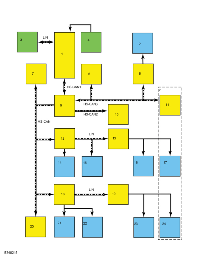
System Diagram - Networked Illumination
.jpg)
| Item | Description |
|---|---|
| 1 | BCM |
| 2 | China only |
| 3 | Headlamp Switch |
| 4 | Light Sensor |
| 5 | FDIM |
| 6 | IPC |
| 7 | FCIM |
| 8 | APIM |
| 9 | GWM |
| 10 | GSM |
| 11 | RACM |
| 12 | DDM |
| 13 | DRDM |
| 14 | LHF Door Lock Switch |
| 15 | LHF Window Control Switch |
| 16 | LHR Window Control Switch |
| 17 | LHR Door Lock Switch |
| 18 | PDM |
| 19 | PRDM |
| 20 | RHVAC |
| 21 | RHF Door Lock Switch |
| 22 | RHF Window Control Switch |
| 23 | RHR Window Control Switch |
| 24 | RHR Door Lock Switch |
Network Message Chart
Module Network Input Messages - APIM , DDM , DRDM , FCIM , GSM , GWM , IPC , PDM , PRDM , RHVAC , and RACM (China only)
| Broadcast Message | Originating Module | Message Purpose |
| Illumination Dimming Level | BCM | Used to command the illumination intensity for networked modules and outputs that are hard-wired to networked modules. |
Networked Illumination Operation
The dimmable switches and components are illuminated when the headlamp switch is in the PARK, ON, or AUTO position. The system-wide illumination intensity is determined by the BCM based on based on inputs from the ambient light sensor and the dimmer switch (iinternal to the headlamp switch).
The BCM sends the dimming level message to the GWM on the HS-CAN1 . The GWM divides the signal between the MS-CAN , HS-CAN2 , and the HS-CAN3 sending messages to the following modules:
The rear door modules receive their dimming level message from the BCM on a LIN connected to the DDM or PDM . The driver side window control switch also uses a LIN to communicate with the DDM .
MS-CAN
- PDM
- DDM
- FCIM
HS-CAN2
- GSM
HS-CAN3
- IPC
- APIM
- RACM (China only)
If the message is not received, or invalid; a CMDTC is set in the respective module, and the illumination level defaults to full intensity.
The IPC allows a 5 second delay before setting a CMDTC and switching to full intensity. During the 5 second delay, the IPC operates at the illumination intensity last received from the BCM .
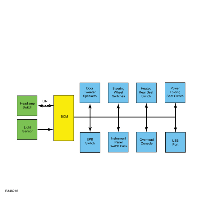
System Diagram - Non-Networked Illumination
.jpg)
| Item | Description |
|---|---|
| 1 | BCM |
| 2 | Door Tweeter Speakers |
| 3 | Steering Wheel Switches |
| 4 | Heated Rear Seat Switch |
| 5 | Power Folding Seat Switch |
| 6 | EPB Switch |
| 7 | Instrument Panel Switch Pack |
| 8 | Overhead Console |
| 9 | USB Port |
| 10 | Light Sensor |
| 11 | Headlamp Switch |
Non-Networked Illumination Operation
The BCM calculates the correct intensity for the non-networked illumination sources based on the ambient light intensity input from the light sensor and the requested illumination intensity level input from the dimmer switch. The BCM provides a pulse-width modulated voltage to all non-networked illumination sources.
Field-Effect Transistor (FET) Protection
The BCM
is protected by the use of a Field-Effect Transistor (FET) on each
output. Refer to the System Diagram to view the different groups of BCM
non-networked illumination outputs. For a full description of
Field-Effect Transistor (FET) protection,
Refer to: Module
Controlled Functions - System Operation and Component Description
(419-10 Multifunction Electronic Modules, Description and Operation).
Component Description
Dimmer Switch
The dimmer switch is a 3 position momentary contact switch, integral to the headlamp switch, providing a non-networked input to the BCM . When the dimmer switch is pressed up for increased illumination intensity, and down for decreased illumination intensity, a ground signal received by the BCM on the corresponding terminal is interpreted as a request to increase or decrease illumination intensity.
 Instrument Panel and Interior Switches Illumination - Overview. Description and Operation
Overview
Dimmable
illumination provides backlighting to switches and control components
when the headlamps or parking lamps are on. The level of intensity is
adjusted by pressing the illumination dim up switch up to increase
intensity or the dim down switch to decrease intensity...
 Instrument Panel and Interior Switches Illumination. Diagnosis and Testing
DTC Chart: Body Control Module (BCM)
Diagnostics in this manual assume a certain skill level and knowledge of Ford-specific diagnostic practices. REFER to: Diagnostic Methods (100-00 General Information, Description and Operation)...
Other information:
Lincoln Nautilus 2018-2025 Service Manual: Body System. Diagnosis and Testing
Symptom Chart(s) Diagnostics in this manual assume a certain skill level and knowledge of Ford-specific diagnostic practices. REFER to: Diagnostic Methods (100-00 General Information, Description and Operation). Dust and Water Leaks Most dust and water leaks occur due to missing or incorrectly installed body sealer or components...
Lincoln Nautilus 2018-2025 Service Manual: Front Toe Adjustment - Vehicles With: Adaptive Steering. General Procedures
Special Tool(s) / General Equipment Wheel Alignment System Adjustment Connect the scan tool and perform the steering toe adjustment. Follow the scan tool directions. NOTE: Make sure that the vehicle is standing on a level surface...
Categories
- Manuals Home
- 1st Generation Nautilus Owners Manual
- 1st Generation Nautilus Service Manual
- Massage Seats
- USB Ports
- Auto-Start-Stop
- New on site
- Most important about car
USB Ports
Locating the USB Ports
Data Transfer USB Ports

The USB Ports could be in the following locations:
On the lower instrument panel. Inside the media bin. Inside the center console.Note: These USB ports can also charge devices.