Lincoln Nautilus: Interior Trim and Ornamentation / Loadspace Trim Panel. Removal and Installation
Lincoln Nautilus 2018-2026 Service Manual / Body and Paint / Body and Paint / Interior Trim and Ornamentation / Loadspace Trim Panel. Removal and Installation
Removal
NOTE: Right hand (RH) shown, left hand (LH) similar.
-
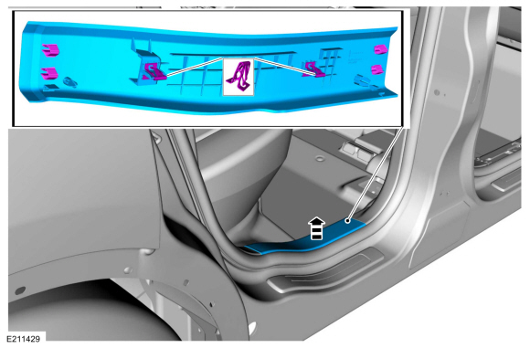
Release the clips and remove the rear door scuff plate trim panel.
 |
-
If equipped.
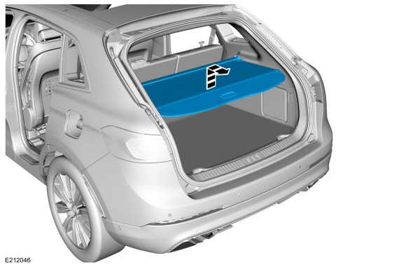
Remove the load compartment cover.
 |
-
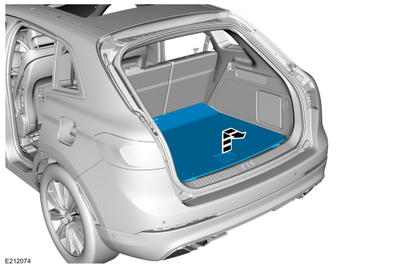
Remove the load compartment floor cover.
 |
-
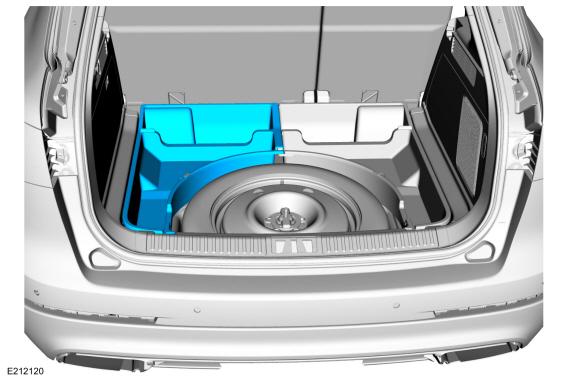
If equipped.
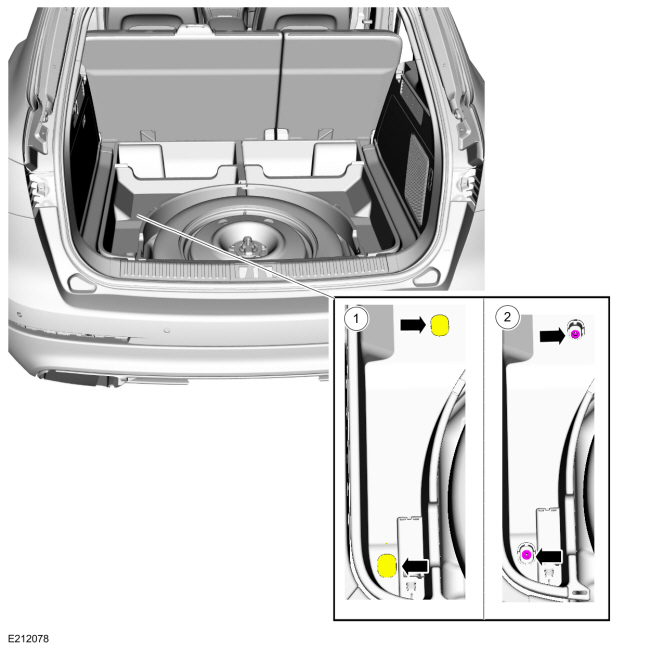
Remove the LH side storage bin retainers.
-
NOTE: The retainer covers have tethers on them and do not fully come off.
Position aside the retainer covers.
-
Remove the retainers.
-
 |
-
If equipped.
Remove the LH side storage bin.
 |
-
If equipped.
Remove the RH side storage bin retainers.
-
NOTE: The retainer covers have tethers on them and do not fully come off.
Position aside the retainer covers.
-
Remove the retainers.
-
 |
-
If equipped.
Remove the RH side storage bin.
.jpg) |
-
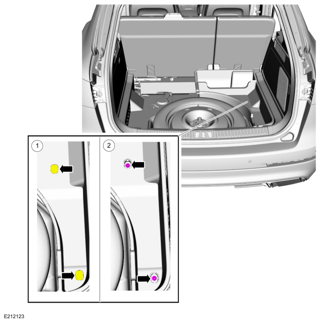
NOTE: Left hand (LH) shown, right hand (RH) similar.
On both sides.
Remove the tie down hooks.
-
Open the retainer cover.
-
Remove the retainer.
-
Remove the tie down hook.
-
Open the retainer cover.
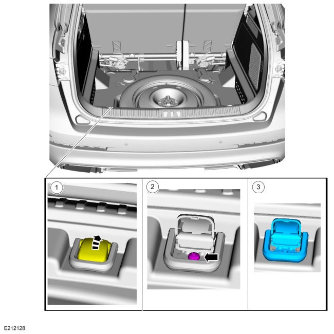 |
-
Remove the load compartment scuff plate trim panel pin-type retainers.
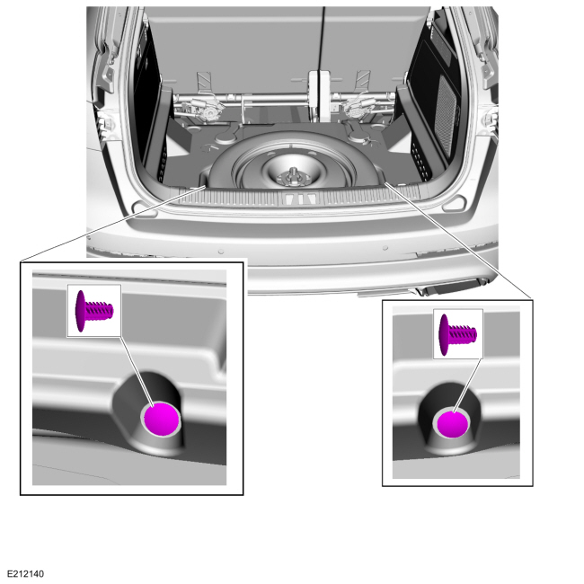 |
-
Release the clips and remove the load compartment scuff plate trim panel.
.jpg) |
-
Remove the rear seat backrest.
Refer to: Rear Seat Backrest (501-10B Rear Seats, Removal and Installation).
-
Remove the loadspace trim panel.
-
Release the clips.
-
If equipped.
Disconnect the bluetooth rear interior antenna electrical connector.
-
Release the clips.
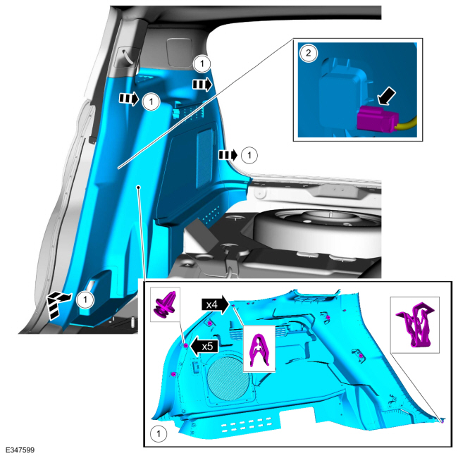 |
Installation
-
To install, reverse the removal procedure.
 Liftgate Trim Panel. Removal and Installation
Removal
Release the clips and remove the liftgate upper center trim panel.
Release the clips and remove the liftgate grab handle cover...
 Loadspace Trim Panel Cargo Net Hook. Removal and Installation
Special Tool(s) /
General Equipment
Flat Headed Screw Driver
Interior Trim Remover
Removal
NOTE:
LH shown, RH similar.
NOTE:
Removal steps in this procedure may contain installation details...
Other information:
Lincoln Nautilus 2018-2026 Service Manual: Cabin Heater Coolant Pump - 2.0L EcoBoost (184kW/250PS) – MI4. Removal and Installation
Special Tool(s) / General Equipment Hose Clamp(s) Removal NOTE: Removal steps in this procedure may contain installation details. WARNING: When releasing the cooling system pressure, cover the coolant expansion tank cap with a thick cloth...
Lincoln Nautilus 2018-2026 Service Manual: Perimeter Anti-Theft Alarm - Component Location. Description and Operation
Item Description 1 BCM 2 Hood latch (with integrated hood ajar switch) 3 Intrusion sensor 4 Anti-theft alarm horn ..
Categories
- Manuals Home
- 1st Generation Nautilus Owners Manual
- 1st Generation Nautilus Service Manual
- Switching the Lane Keeping System On and Off. Switching the Lane Keeping System Mode
- Folding the Exterior Mirrors - Vehicles With: Manual Folding Mirrors. Folding the Exterior Mirrors - Vehicles With: Power Folding Mirrors
- Interior Lamp Function. Adjusting the Instrument Panel Lighting Brightness. Ambient Lighting. Interior Lighting – Troubleshooting
- New on site
- Most important about car
Parking Aid Indicators. Parking Aids – Troubleshooting
Parking Aid Indicators
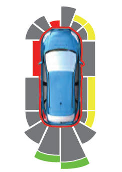
The system provides object distance indication through the information and entertainment display.
As the distance to the object decreases, the indicator waves and the lines move toward the vehicle icon. If there is no object detected, the distance indicator lines are grey.Copyright © 2026 www.linautilus.com