Lincoln Nautilus: Steering Wheel and Column Electrical Components / Steering Wheel and Column Electrical Components - System Operation and Component Description. Description and Operation
System Operation
System Diagram - Push Button Ignition Switch
E343638 *.sttxt { visibility: hidden; } *.stcallout { visibility: visible; } 1 GWM 2 PCM 3 Ignition Switch (Push Button) 4 Ignition Mode Indicator 5 BCM 6 Run/Start Relay| Item | Description |
|---|---|
| 1 | GWM |
| 2 | PCM |
| 3 | Ignition Switch (Push Button) |
| 4 | Ignition Mode Indicator |
| 5 | BCM |
| 6 | Run/Start Relay |
Network Message Chart - Push Button Ignition Switch
GWM Module Network Input Messages
| Broadcast Message | Originating Module | Message Purpose |
|---|---|---|
| Ignition status | BCM | This message informs the GWM of the current ignition status; off, run, start, unknown or invalid which then transmits the message to modules on other networks. |
PCM Module Network Input Messages
| Broadcast Message | Originating Module | Message Purpose |
|---|---|---|
| Ignition status | BCM | This message informs the PCM of the current ignition status; off, run, start, unknown or invalid. |
Push Button Ignition Switch
The push button ignition switch (integrated into the GSM is used to control the ignition mode.
There are two circuits the BCM
monitors from the push button ignition switch to change the ignition
mode. One circuit is monitored for voltage and the other for a ground
signal. When the START/STOP button is pressed, one circuit routes
battery voltage to the BCM while a voltage signal from the BCM
on the second circuit is routed to ground, indicating a request to
change the ignition mode. Changing the ignition mode out of OFF works in
conjunction with the PATS . The BCM must recognize a valid programmed
key before it changes the ignition mode out of OFF. For information
regarding the PATS ,
Refer to: Passive Anti-Theft System (PATS) -
System Operation and Component Description (419-01B Passive Anti-Theft
System (PATS), Description and Operation).
The BCM contains a non-serviceable run/start relay.
Additionally, the BCM controls a serviceable run/start relay located in the BJB .
When the relays are activated, they provide voltage to various vehicle electrical systems.
Refer to the following table for information about achieving the various ignition modes.
| Ignition Mode Entry Condition | Desired Ignition Mode | Action To Take |
|---|---|---|
| OFF | ON (engine off) | Press the START/STOP button without applying the brake pedal. |
| OFF or ON | ON (engine running) | Apply the brake pedal and then press the START/STOP button. |
| ON (engine off) | OFF | Press the START/STOP button. |
| ON (engine running) | OFF | Press the START/STOP button. |
Ignition Mode LED Indicator
The ignition mode LED indicates the ignition mode of the vehicle. The BCM controls the voltage to the ignition mode LED indicator. Refer to the following table.
| Ignition Mode | Ignition Mode LED Indicator |
|---|---|
| OFF | Off |
| ON (engine off) | Flashing |
| ON (engine running) | On |
OFF
The BCM controls the relays providing voltage to the vehicle electrical systems. When the ignition is in the ON mode, a single press and release of the START/STOP button (without applying the brake pedal) changes the ignition to the OFF mode. No programmed key is required to change the ignition to the OFF mode when the vehicle is running.
If the vehicle is in motion, a momentary press of the START/STOP button does not shut the vehicle off. If the vehicle is moving at a speed greater than 15 km/h (9 mph), the START/STOP button must be pressed and held for longer than one second (or pressed 3 times within 2 seconds) to turn the ignition off.
When the BCM changes the ignition mode to OFF, it communicates the ignition mode to the other modules by sending an ignition status message over the CAN .
ON
When the ignition is in the ON mode, the BCM activates the run/start relays to provide voltage to the vehicle electrical systems and communicates the ignition mode to the other modules by sending an ignition status message over the CAN .
When the vehicle enters ON mode, multiple indicators in the IPC prove out and the IPC displays the gear selection and the vehicle mileage.
START
The vehicle temporarily enters the START mode if the brake pedal is applied when the START/STOP button is pressed, and a valid programmed key is detected within the vehicle.
In addition to activating the run/start relays, the BCM communicates the ignition mode to the other modules by sending an ignition status message over the CAN .
After the ignition has completed the vehicle start sequence, the ignition mode returns to ON and the ignition mode LED in the START/STOP button illuminates steadily.
The engine can be started from any ignition mode.
System Diagram - Heated Steering Wheel (vehicles not equipped with adaptive steering)
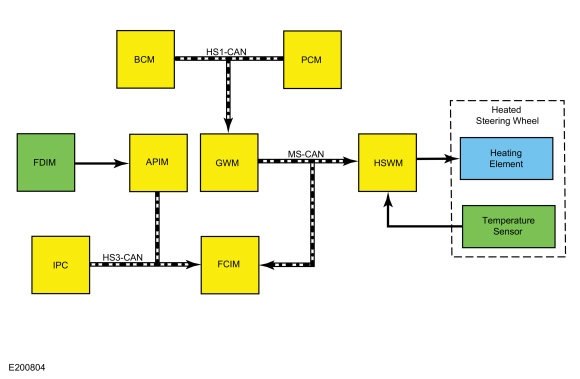

| Item | Description |
|---|---|
| 1 | MS-CAN |
| 2 | HS-CAN3 |
| 3 | HS-CAN1 |
| 4 | FDIM |
| 5 | FCIM |
| 6 | APIM |
| 7 | IPC |
| 8 | HSWM |
| 9 | GWM |
| 10 | BCM |
| 11 | PCM |
| 12 | Temperature sensor |
| 13 | Heated steering wheel |
| 14 | Heating element |
Network Message Chart - Heated Steering Wheel
HSWM Network Input Messages
| Broadcast Message | Originating Module | Message Purpose |
|---|---|---|
| Engine status | PCM | This message indicates to the HSWM whether the engine is running. |
| Ignition status | BCM | Indicates which ignition mode is active. |
| Steering wheel heat request | FCIM | Message is used to activate the heated steering wheel function when the touchscreen button is pressed on the FDIM , or when the conditions are met to activate the heated steering wheel (and heated seats) during a remote start. |
FCIM Module Network Input Messages
| Broadcast Message | Originating Module | Message Purpose |
|---|---|---|
| Steering wheel heat request | APIM | This message informs the FCIM that the heated steering wheel touchscreen button was pressed on the FDIM . |
| Ambient air temperature filtered | IPC | This message is used by the FCIM when determining if outside conditions are cold enough to request the heated steering wheel be activated during remote start operation. |
Heated Steering Wheel
When the engine is running and the HSWM receives a request to heat the steering wheel, the HSWM applies voltage and ground to the steering wheel heating elements (integral to the steering wheel) to heat the steering wheel to a temperature of approximately 82-94°F (28-34°C). The heated steering wheel temperature is maintained by the HSWM using a temperature sensor in the steering wheel.
The HSWM supplies voltage and ground to the heating elements integral to the steering wheel and maintains the temperature based on the steering wheel temperature sensor reading until the heated steering wheel is switched off on the FDIM or the ignition is turned off.
The controls and indicators for the heated steering wheel system are located on the FDIM (touchscreen) only. The FDIM does not communicate on any network and is connected directly to the APIM .
Remote Start System
The heated steering wheel system (along with the heated front seats) may be configured using the message center to activate when the remote start feature is used, based on outside air temperature. During remote start, the outside air temperature is continually monitored by the HVAC system. The heated steering wheel system activation changes if the outside air changes from cold to moderate or warm temperatures or back from moderate or warm to cold temperatures.
System Diagram - Heated Steering Wheel (vehicles equipped with adaptive steering)
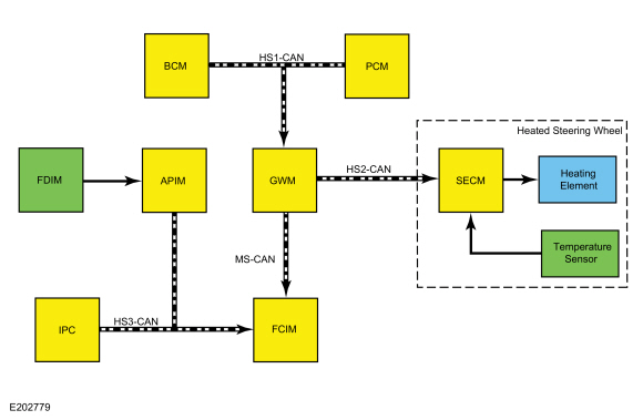
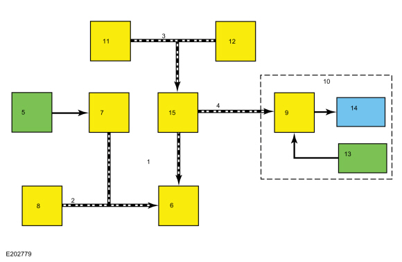
| Item | Description |
|---|---|
| 1 | MS-CAN |
| 2 | HS-CAN3 |
| 3 | HS-CAN1 |
| 4 | HS-CAN2 |
| 5 | FDIM |
| 6 | FCIM |
| 7 | APIM |
| 8 | IPC |
| 9 | SECM |
| 10 | Heated steering wheel |
| 11 | BCM |
| 12 | PCM |
| 13 | Temperature sensor |
| 14 | Heating element |
| 15 | GWM |
Network Message Chart - Heated Steering Wheel
SECM Network Input Messages
| Broadcast Message | Originating Module | Message Purpose |
|---|---|---|
| Engine status | PCM | This message indicates to the HSWM whether the engine is running. |
| Ignition status | BCM | Indicates which ignition mode is active. |
| Steering wheel heat request | FCIM | Message is used to activate the heated steering wheel function when the touchscreen button is pressed on the FDIM , or when the conditions are met to activate the heated steering wheel (and heated seats) during a remote start. |
FCIM Module Network Input Messages
| Broadcast Message | Originating Module | Message Purpose |
|---|---|---|
| Steering wheel heat request | APIM | This message informs the FCIM that the heated steering wheel touchscreen button was pressed on the FDIM . |
| Ambient air temperature filtered | IPC | This message is used by the FCIM when determining if outside conditions are cold enough to request the heated steering wheel be activated during remote start operation. |
Heated Steering Wheel
When the SECM receives a request to heat the steering wheel and the engine is running, the SECM applies voltage and ground to the steering wheel heating elements (integral to the steering wheel) to heat the steering wheel to a temperature of approximately 82-94°F (28-34°C). The heated steering wheel temperature is maintained by the SECM using a temperature sensor in the steering wheel.
The SECM supplies voltage and ground to the heating elements integral to the steering wheel and maintains the temperature based on the steering wheel temperature sensor reading until the heated steering wheel is switched off on the FDIM or the ignition is turned off.
The controls and indicators for the heated steering wheel system are located on the FDIM (touchscreen) only. The FDIM does not communicate on any network and is connected directly to the APIM .
Remote Start System
The heated steering wheel system (along with the heated front seats) may be configured using the message center to activate when the remote start feature is used, based on outside air temperature. During remote start, the outside air temperature is continually monitored by the HVAC system. The heated steering wheel system activation changes if the outside air changes from cold to moderate or warm temperatures or back from moderate or warm to cold temperatures.
Component Description
Push Button Ignition Switch
The push button ignition switch is a momentary dual contact switch that provides direct input to the BCM and PCM . Both sets of contacts are normally open. When the START/STOP button is pressed, one set of contacts provides a ground signal to the BCM and the other set of contacts supplies voltage to the BCM and the PCM .
The ignition mode LED indicator is located near the top of the START/STOP button and is controlled by the BCM .
The ignition switch is part of the GSM .
Heated Steering Wheel
The steering wheel heater element is part of the steering wheel and cannot be serviced separately. The steering wheel temperature sensor is part of the steering wheel and cannot be serviced separately.
HSWM (vehicles not equipped with adaptive steering)
The HSWM controls the steering wheel heating elements. The HSWM uses the steering wheel temperature sensor to maintain the steering wheel temperature. The HSWM supplies voltage and ground to the heating elements integral to the steering wheel and maintains the temperature based on the steering wheel temperature sensor reading until the heated steering wheel is switched off on the FDIM or the ignition is turned off.
The HSWM requires PMI when replaced.
SECM (vehicles equipped with adaptive steering)
The SECM controls the steering wheel heating elements. The SECM uses the steering wheel temperature sensor to maintain the steering wheel temperature. The SECM supplies voltage and ground to the heating elements integral to the steering wheel and maintains the temperature based on the steering wheel temperature sensor reading until the heated steering wheel is switched off on the FDIM or the ignition is turned off.
The SECM cannot be serviced independently. It is only replaced as an assembly with the steering wheel.
The SECM requires PMI when replaced.
BCM
The BCM controls the run/start relays and sets the vehicle ignition mode based on inputs from the ignition switch, or push button ignition switch. It communicates the ignition mode to other modules over the CAN . If a fault is detected with the ignition switch system, Diagnostic Trouble Codes (DTCs) are set in the BCM .
When the BCM is replaced, the parameter reset and PMI procedures must be carried out and at least 2 keys programmed to it.
 Steering Wheel and Column Electrical Components - Overview. Description and Operation
Steering Column Switches Overview
The
steering column switches are located on and around the steering column.
They enable the driver to control various vehicle functions while
remaining focused on driving...
 Steering Wheel and Column Electrical Components. Diagnosis and Testing
DTC Charts
Diagnostics in this manual assume a certain skill level and knowledge of Ford-specific diagnostic practices. REFER to: Diagnostic Methods (100-00 General Information, Description and Operation)...
Other information:
Lincoln Nautilus 2018-2025 Service Manual: Front Wheel Bearing and Wheel Hub. Removal and Installation
Special Tool(s) / General Equipment 204-161 (T97P-1175-A) Installer, HalfshaftTKIT-1997-LM2TKIT-1997-F/FM2TKIT-1997-FLM2 205-D070 (D93P-1175-B) Remover, Front Wheel Hub Removal NOTICE: Suspension fasteners are critical parts that affect the performance of vital components and systems...
Lincoln Nautilus 2018-2025 Service Manual: Windshield Washer Pump. Removal and Installation
Special Tool(s) / General Equipment Fluid Suction Gun Fluid Container Materials Name Specification Motorcraft® Premium Windshield Wash Concentrate with BitterantZC-32-B2 WSS-M14P19-A Removal NOTE: Hood removed in this procedure for clarity...
Categories
- Manuals Home
- 1st Generation Nautilus Owners Manual
- 1st Generation Nautilus Service Manual
- Normal Scheduled Maintenance
- Fuel Quality
- Interior Lamp Function. Adjusting the Instrument Panel Lighting Brightness. Ambient Lighting. Interior Lighting – Troubleshooting
- New on site
- Most important about car
USB Ports
Locating the USB Ports
Data Transfer USB Ports

The USB Ports could be in the following locations:
On the lower instrument panel. Inside the media bin. Inside the center console.Note: These USB ports can also charge devices.