Lincoln Nautilus: Multifunction Electronic Modules / Module Controlled Functions - System Operation and Component Description. Description and Operation
System Operation
Body Control Module (BCM)
The BCM controls various systems by monitoring inputs from switches, sensors and network messages from other modules on the HS-CAN1 and from the GWM . Based on the inputs received, the BCM activates outputs. For example, the BCM monitors the headlamp switch position. Based on this input, the BCM may provide voltage to the exterior lamps.
Battery Saver
The battery saver feature is used to conserve battery voltage. The BCM provides automatic shut-off of the interior lamps after a time-out period when the ignition is off.
Refer to: Interior Lighting (417-02)
.
Battery Load Shed
The BCM monitors the battery state of charge and when necessary will shut off accessories in order to save the remaining battery charge.
Refer to: Charging System - 2.0L EcoBoost (184kW/250PS) - MI4 (414-00)
.
Refer to: Charging System - 2.7L EcoBoost (238kW/324PS) (414-00)
.
Refer to: Charging System - 3.7L Duratec (227kW/301PS) (414-00)
.
Field Effect Transistor (FET) Protection
The BCM utilizes an Field Effect Transistor (FET) protective circuit strategy for many of its outputs, for example, lamp output circuits. Output loads (current level) are monitored for excessive current (typically short circuits) and are shut down (turns off the voltage or ground provided by the module) when a fault event is detected.
A Field Effect Transistor (FET) is a type of transistor that the control module software uses to control and monitor current flow on module outputs. The Field Effect Transistor (FET) protection strategy prevents module damage in the event of excessive current flow.
Output loads (current level) are monitored for excessive current draw (typically short circuits). When a fault event is detected the Field Effect Transistor (FET) turns off and a short circuit DTC sets. The module resets the Field Effect Transistor (FET) protection and allows the circuit to function when the fault is corrected or the ignition state is cycled off and then back on.
When the excessive circuit load occurs often enough, the module shuts down the output until a repair procedure is carried out. Each Field Effect Transistor (FET) protected circuit has 3 predefined levels of short circuit tolerance based on a module lifetime level of fault events based upon the durability of the Field Effect Transistor (FET). If the total tolerance level is determined to be 600 fault events, the 3 predefined levels would be 200, 400 and 600 fault events.
When each level is reached, the DTC associated with the short circuit sets along with DTC U1000:00. These Diagnostic Trouble Codes (DTCs) can be cleared using the module on-demand self-test, then the Clear DTC operation on the scan tool (if the on-demand test shows the fault corrected). The module never resets the fault event counter to zero and continues to advance the fault event counter as short circuit fault events occur.
If the number of short circuit fault events reach the third level, then Diagnostic Trouble Codes (DTCs) U1000:00 and U3000:49 set along with the associated short circuit DTC . DTC U3000:49 cannot be cleared and the module must be replaced after the repair.
Post Crash Alert Function
The post crash alert is a function controlled by the BCM . If the RCM determines an impact of enough severity has occurred (the airbags may or may not be deployed), the post crash alert function activates.
The post crash alert function:
- sounds the horn.
- turns on the hazard lights.
- turns on the interior lights.
- unlocks the doors.
The post crash alert function can be turned off by:
- pressing the hazard flasher lamp switch (which may need to be pressed twice).
- pressing the transmitter unlock button.
- pressing the RKE transmitter PANIC button.
- cycling the ignition switch (RUN-OFF-RUN-OFF-RUN).
- opening the driver door.
Factory-Transport Mode
During vehicle build, some modules (such as the IPC and the BCM ) are set to factory mode. When the vehicle build is complete, the vehicle is set to transport mode.
Transport
mode is used to reduce the drain on the battery during longer periods
when the vehicle is not used. Various system functions can be altered or
disabled when in the transport mode. While in transport mode, the IPC
displays TRANSPORT MODE in the message center. Transport mode can be
disabled and placed into normal operation mode.
Refer to: Transport Mode Deactivation (419-10 Multifunction Electronic Modules, General Procedures).
Car Configuration Parameters
The parameters are set in the BCM . The parameters are also set in
the IPC as backup data for service, in case online As-Built data is not
available. For more information,
Refer to: Module Configuration (418-01)
.
Component Description
BCM
The BCM is a multifunction module that requires a PMI when replaced.
Refer to: Module Programming (418-01)
.
DDM
The DDM receives power window commands from the driver door window control switch through a LIN . The DDM supplies voltage and ground to operate the driver door window regulator motor. The DDM also communicates driver door window control switch requests to the PDM through the MS-CAN .
For the power mirror functions, the DDM controls the LH exterior mirror glass position by supplying voltage and ground to the LH exterior mirror motors based on inputs from the master window control switch. When the RH exterior mirror is selected, the DDM forwards the movement requests to the PDM through the MS-CAN . To control the heated mirror function, the DDM supplies voltage and ground to the LH exterior mirror glass heating element based on messages received from the FCIM . For the memory mirror function, the DDM supplies voltage and ground to the LH mirror motor potentiometers. The DDM monitors the feedback from these potentiometers to determine the mirror glass position. Memory mirror positions are stored in the DDM memory. For more information:
-
Refer to: Handles, Locks, Latches and Entry Systems (501-14) .
-
Refer to: Glass, Frames and Mechanisms (501-11) .
-
Refer to: Rear View Mirrors - System Operation and Component Description (501-09 Rear View Mirrors, Description and Operation).
The DDM requires PMI when replaced.
Refer to: Module Programming (418-01)
.
PDM
For the power window function, the PDM receives power window commands from the passenger door window control switch or from the DDM through the MS-CAN .
For the power mirror function, the PDM controls the RH exterior mirror glass position by supplying voltage and ground to the RH exterior mirror motors based on messages received from the DDM . To control the heated mirror function, the PDM supplies voltage and ground to the RH exterior mirror glass heating element based on messages received from the FCIM . For the memory mirror function, the PDM supplies voltage and ground to the RH mirror motor potentiometers. The PDM monitors the feedback from these potentiometers to determine the mirror glass position. Passenger mirror positions are stored in the PDM memory. For more information:
-
Refer to: Handles, Locks, Latches and Entry Systems (501-14) .
-
Refer to: Glass, Frames and Mechanisms (501-11) .
-
Refer to: Rear View Mirrors - System Operation and Component Description (501-09 Rear View Mirrors, Description and Operation).
The PDM requires PMI when replaced.
Refer to: Module Programming (418-01)
.
RTM
The RTM communicates all RKE and passive key information to the BCM over a LIN circuit and (when the network is awake) the CAN . The RTM is an antenna that receives the high frequency signals from passive keys.
-
Refer to: Handles, Locks, Latches and Entry Systems (501-14) .
-
Refer to: Tire Pressure Monitoring System (TPMS) - System Operation and Component Description (204-04B Tire Pressure Monitoring System (TPMS), Description and Operation).
-
Refer to: Rear View Mirrors - System Operation and Component Description (501-09 Rear View Mirrors, Description and Operation).
The RTM requires PMI when replaced.
Refer to: Module Programming (418-01)
.

 Body Control Module (BCM). Diagnosis and Testing
DTC Chart: BCM
Diagnostics in this manual assume a certain skill level and knowledge of Ford-specific diagnostic practices. REFER to: Diagnostic Methods (100-00 General Information, Description and Operation)...
Other information:
Lincoln Nautilus 2018-2026 Service Manual: Controller Area Network (CAN) Module Communications Network. Diagnosis and Testing
Diagnostic Trouble Code (DTC) Chart Diagnostics in this manual assume a certain skill level and knowledge of Ford-specific diagnostic practices. REFER to: Diagnostic Methods (100-00 General Information, Description and Operation). Module DTC Description Action GWM U0001:09 High Speed CAN Communication Bus: Component Failures GO to Pinpoint Test AR GWM U0214:00 Lost Commun..
Lincoln Nautilus 2018-2026 Owners Manual: Post-Crash Alert System
What Is the Post-Crash Alert System The system helps draw attention to your vehicle in the event of a serious impact. How Does the Post-Crash Alert System Work The system is designed to turn the hazard flashers on and to intermittently sound the horn in the event of a serious impact that deploys an airbag or the seatbelt pretensioners. Post-Crash Alert System Limitations Depending on applicab..
Categories
- Manuals Home
- 1st Generation Nautilus Owners Manual
- 1st Generation Nautilus Service Manual
- Switching the Lane Keeping System On and Off. Switching the Lane Keeping System Mode
- Interior Lamp Function. Adjusting the Instrument Panel Lighting Brightness. Ambient Lighting. Interior Lighting – Troubleshooting
- Auto-Start-Stop
- New on site
- Most important about car
Parking Aid Indicators. Parking Aids – Troubleshooting
Parking Aid Indicators
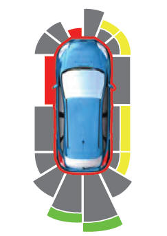
The system provides object distance indication through the information and entertainment display.
As the distance to the object decreases, the indicator waves and the lines move toward the vehicle icon. If there is no object detected, the distance indicator lines are grey.