Lincoln Nautilus: Body Closures / Liftgate Alignment. General Procedures
Inspection
NOTE:
Removal steps in this procedure may contain installation details.
-
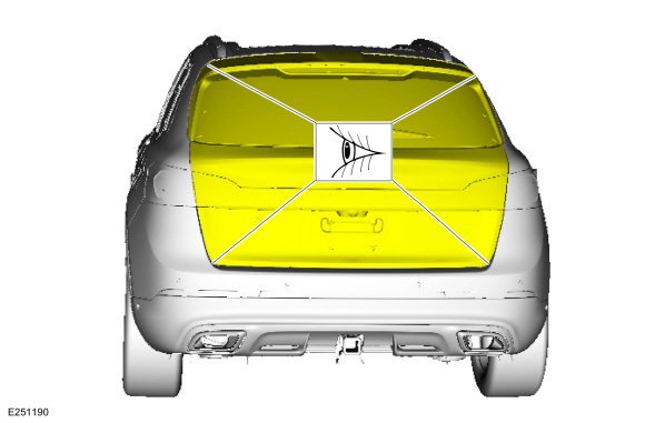
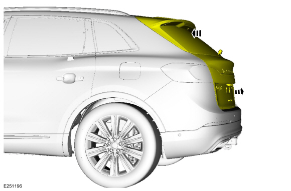
Check liftgate-to-body dimensions.
Refer to: Body and Frame (501-26 Body Repairs - Vehicle Specific Information and Tolerance Checks, Description and Operation).
Adjustment
All alignments
-
Open the liftgate.
-
If equipped.
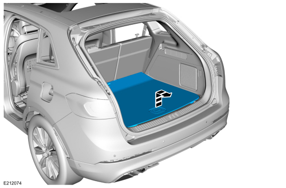
Remove the load compartment cover.
-
Remove the load compartment floor cover.
-
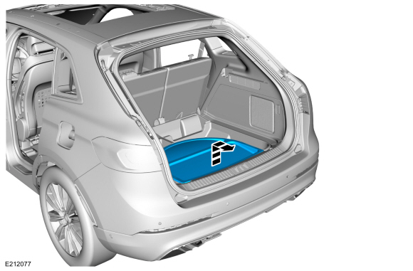
If equipped.
Remove the spare tire cover.
-
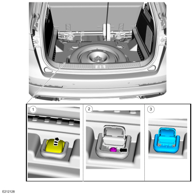
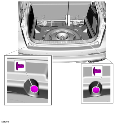
On both sides.
Remove the tie down hooks.
-
Open the retainer cover.
-
Remove the retainers.
-
Remove the tie down hook.
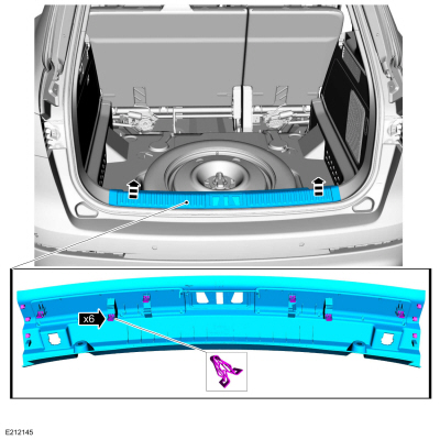
-
Remove the load compartment scuff plate trim panel pin-type retainers.
-
Release the clips and remove the load compartment scuff plate trim panel.
-
Remove the liftgate striker.
Torque:
177 lb.in (20 Nm)
Liftgate left and right, up and down alignment
-
Loosen the bolts enough to permit movement of the liftgate.
-
Close the liftgate.
-
Adjust the liftgate to specification.
Refer to: Body and Frame (501-26 Body Repairs - Vehicle Specific Information and Tolerance Checks, Description and Operation).
-
Open the liftgate.
-
Tighten the bolts.
Torque:
22 lb.ft (30 Nm)
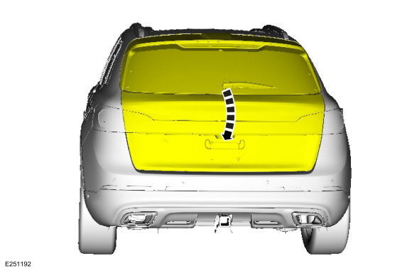
Liftgate in and out alignment
-
Lower the headliner.
Refer to: Headliner - Lowering (501-05 Interior Trim and Ornamentation)
.
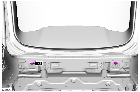
-
Loosen the nuts.
-
NOTE:
Nominal overslam bumpers have a small lip and should be adjusted flush with the sheet metal surface.
Adjust the nominal overslam bumpers.
-
Close the liftgate.
-
Adjust the liftgate to specification.
Refer to: Body and Frame (501-26 Body Repairs - Vehicle Specific Information and Tolerance Checks, Description and Operation).
-
Carefully open the liftgate.
-
Tighten the nuts.
Torque:
46 lb.ft (62.5 Nm)
All alignments
-
Install the liftgate striker.
-
Close the liftgate.
-
Inspect the body-to-liftgate door dimensions.
Refer to: Body and Frame (501-26 Body Repairs - Vehicle Specific Information and Tolerance Checks, Description and Operation).
-
Install the removed components.
-
If equipped.
Carry out the power liftgate initialization.
Refer to: Power Liftgate Initialization (501-03 Body Closures, General Procedures).
Inspection
NOTE:
Removal steps in this procedure may contain installation details.
Inspect the hood-to-body dimensions.
Refer to: Body and Frame (501-26 Body Repairs - Vehicle Specific Information and Tolerance Checks, Description and Operation)...
Initialization
Disconnect the battery or remove the RGTM fuse(s).
Refer to: Battery Disconnect and Connect (414-01 Battery, Mounting and Cables, General Procedures)...
Other information:
Removal
Remove the instrument panel.
Refer to: Instrument Panel (501-12 Instrument Panel and Console, Removal and Installation).
Disconnect the electrical connector.
Rotate and remove the sensor.
Installation
To install, reverse the removal procedure...
Specifications
Item
Specification
Rear fixed glass panel to roof flushness, side (at front of glass)
-0.08 - 0.0 in (-0.5 - 0.0 mm)
Rear fixed glass panel to roof flushness, rear
0...
Categories
WARNING: If the tire pressure
monitor sensor becomes damaged it may
not function.
Note: The use of tire sealant may damage
your tire pressure monitoring system and
should only be used in roadside
emergencies. If you must use a sealant, use
the Tire Mobility Kit sealant. Replace the tire
pressure monitoring system sensor and
valve stem on the wheel by an authorized
dealer after use of the sealant.
Note: The tire pressure monitoring system
indicator light will illuminate when the spare
tire is in use. To restore the full function of
the monitoring system, all road wheels
equipped with tire pressure monitoring
sensors must be mounted on the vehicle.
If you get a flat tire while driving, do not apply
the brake hea
read more
.jpg)
.jpg)
.jpg)
.jpg)
.jpg)
.jpg)
 Hood Alignment. General Procedures
 Power Liftgate Initialization. General Procedures