Lincoln Nautilus: Rear End Sheet Metal Repairs / Rear Side Member Reinforcement Panel. Removal and Installation
Special Tool(s) / General Equipment
| 8 mm Drill Bit | |
| MIG/MAG Welding Equipment | |
| Spot Weld Drill Bit | |
| Locking Pliers |
Materials
| Name | Specification |
|---|---|
| Metal Bonding Adhesive TA-1, TA-1-B, 3M™ 08115, LORD Fusor® 108B, Henkel Teroson EP 5055 |
- |
Removal
NOTE: Left hand (LH) side shown, right hand (RH) side similar.
NOTE: Factory welds may be substituted with resistance or metal inert gas (MIG) plug welds. Resistance welds may not be placed directly over original location. They must be placed adjacent to original location and match factory welds in quantity. Metal inert gas (MIG) plug welds must equal factory welds in both location and quantity.
NOTE: Adequately protect all adjacent areas against cutting, grinding and welding procedures.
-
Depower the SRS .
Refer to: Supplemental Restraint System (SRS) Depowering (501-20B Supplemental Restraint System, General Procedures).
-
If Required:
Dimensionally restore the vehicle to pre-damage condition.
Refer to: Body and Frame (501-26 Body Repairs - Vehicle Specific Information and Tolerance Checks, Description and Operation).
-
Remove the rear floor panel.
Refer to: Rear Floor Panel (501-30 Rear End Sheet Metal Repairs, Removal and Installation).
-
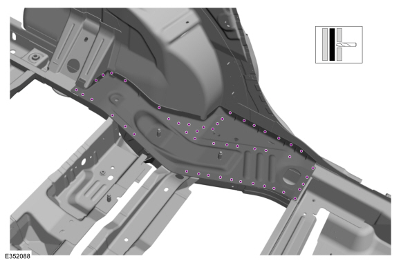
Remove the welds.
Use the General Equipment: Spot Weld Drill Bit
 |
-
Remove the reinforcement.
Use the General Equipment: Spot Weld Drill Bit
.jpg) |
Installation
NOTE: Left hand (LH) side shown, right hand (RH) side similar.
NOTE: Factory welds may be substituted with resistance or metal inert gas (MIG) plug welds. Resistance welds may not be placed directly over original location. They must be placed adjacent to original location and match factory welds in quantity. Metal inert gas (MIG) plug welds must equal factory welds in both location and quantity.
NOTE: Adequately protect all adjacent areas against cutting, grinding and welding procedures.
-
Drill plug weld holes in the reinforcement panel.
Use the General Equipment: 8 mm Drill Bit
.jpg) |
-
Apply adhesive.
Material: Metal Bonding Adhesive / TA-1, TA-1-B, 3M™ 08115, LORD Fusor® 108B, Henkel Teroson EP 5055
.jpg) |
-
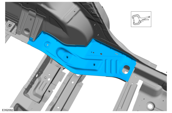
Install, properly position, clamp the replacement reinforcement.
Use the General Equipment: Locking Pliers
 |
-
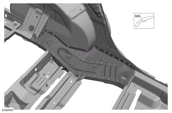
Install the welds.
Use the General Equipment: MIG/MAG Welding Equipment
 |
-
Dress all welds as required using typical metal finishing techniques.
-
Refinish the entire repair using a Ford approved paint system.
-
Restore corrosion protection.
Refer to: Corrosion Prevention (501-25 Body Repairs - General Information, General Procedures).
-
Install the rear floor panel.
Refer to: Rear Floor Panel (501-30 Rear End Sheet Metal Repairs, Removal and Installation).
-
Repower the SRS .
Refer to: Supplemental Restraint System (SRS) Repowering (501-20B Supplemental Restraint System, General Procedures).
 Rear Side Member. Removal and Installation
Special Tool(s) /
General Equipment
MIG/MAG Welding Equipment
Spot Weld Drill Bit
Removal
NOTICE:
The rear side member(s) are constructed of Dual Phase
(DP) 800 steel and cannot be sectioned...
 Rear Suspension Bracket Reinforcement. Removal and Installation
Special Tool(s) /
General Equipment
8 mm Drill Bit
MIG/MAG Welding Equipment
Spot Weld Drill Bit
Locking Pliers
Removal
NOTE:
LH side shown, RH side similar...
Other information:
Lincoln Nautilus 2018-2026 Service Manual: Seatbelt Procedure After a Collision. General Procedures
Inspection WARNING: All seatbelt components must be inspected and corrected as part of any collision repair. Inspect all seatbelt components as prescribed by Seatbelt Procedure After a Collision found in Section 501-20A General Procedures of this manual...
Lincoln Nautilus 2018-2026 Owners Manual: Switching Climate Control On and Off. Switching Recirculated Air On and Off. Switching Air Conditioning On and Off. Switching Maximum Defrost On and Off. Switching Maximum Cooling On and Off
Switching Climate Control On and Off Press the button. Switching Recirculated Air On and Off Press the button to recirculate air currently in the passenger compartment. Note: Recirculated air could turn off or be prevented from turning on in all air flow modes except maximum cooling to reduce the risk of the windows fogging up...
Categories
- Manuals Home
- 1st Generation Nautilus Owners Manual
- 1st Generation Nautilus Service Manual
- Folding the Exterior Mirrors - Vehicles With: Manual Folding Mirrors. Folding the Exterior Mirrors - Vehicles With: Power Folding Mirrors
- Auto-Start-Stop
- Anti-Theft Alarm System Settings. Security – Troubleshooting
- New on site
- Most important about car
Opening and Closing the Hood
Opening the Hood