Lincoln Nautilus: Rear End Sheet Metal Repairs / Rear Suspension Bracket Reinforcement. Removal and Installation
Special Tool(s) / General Equipment
| 8 mm Drill Bit | |
| MIG/MAG Welding Equipment | |
| Spot Weld Drill Bit | |
| Locking Pliers |
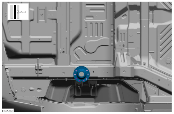
Removal
NOTE: LH side shown, RH side similar.
NOTE: Factory welds may be substituted with resistance or metal inert gas (MIG) plug welds. Resistance welds may not be placed directly over original location. They must be placed adjacent to original location and match factory welds in quantity. Metal inert gas (MIG) plug welds must equal factory welds in both location and quantity.
NOTE: Adequately protect all adjacent areas against cutting, grinding and welding procedures.
-
Remove the lower suspension arm and spring.
Refer to: Lower Arm (204-02 Rear Suspension, Removal and Installation).
Refer to: Spring (204-02 Rear Suspension, Removal and Installation).
-
Remove the spring seat.
-
Remove the welds and bracket.
Use the General Equipment: Spot Weld Drill Bit
 |
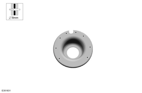
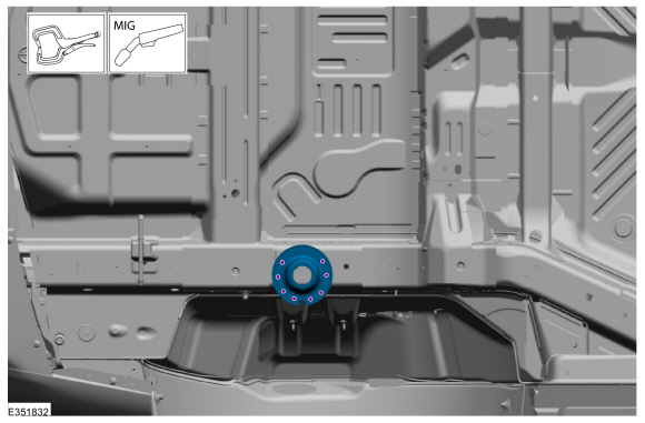
Installation
NOTICE: If refinishing cure temperatures exceed 60° C (140° F), the charge port light ring on plug-in vehicles must be removed.
NOTE: LH side shown, RH side similar.
NOTE: Factory welds may be substituted with resistance or metal inert gas (MIG) plug welds. Resistance welds may not be placed directly over original location. They must be placed adjacent to original location and match factory welds in quantity. Metal inert gas (MIG) plug welds must equal factory welds in both location and quantity.
NOTE: Adequately protect all adjacent areas against cutting, grinding and welding procedures.
-
Drill plug weld holes in the replacement bracket.
Use the General Equipment: 8 mm Drill Bit
 |
-
Install, properly position, clamp and weld the replacement bracket.
Use the General Equipment: Locking Pliers
Use the General Equipment: MIG/MAG Welding Equipment
 |
-
Refinish the entire repair using a Ford approved paint system.
-
Restore corrosion protection.
Refer to: Corrosion Prevention (501-25 Body Repairs - General Information, General Procedures).
-
Install the rear spring seat.
-
Install the lower suspension arm and spring.
Refer to: Lower Arm (204-02 Rear Suspension, Removal and Installation).
Refer to: Spring (204-02 Rear Suspension, Removal and Installation).
 Rear Side Member Reinforcement Panel. Removal and Installation
Special Tool(s) /
General Equipment
8 mm Drill Bit
MIG/MAG Welding Equipment
Spot Weld Drill Bit
Locking Pliers
Materials
Name
Specification
Metal Bonding AdhesiveTA-1, TA-1-B, 3M™ 08115, LORD Fusor® 108B, Henkel Teroson EP 5055
-
Removal
NOTE:
Left hand (LH) side shown, right hand (RH) side similar...
 Rear Wheelhouse Outer. Removal and Installation
Special Tool(s) /
General Equipment
Resistance Spotwelding Equipment
Spherical Cutter
Plasma Cutter
Air Body Saw
MIG/MAG Welding Equipment
Locking Pliers
Materials
Name
Specification
Seam SealerTA-2-B, 3M™ 08308, LORD Fusor® 803DTM
-
Removal
Restore vehicle to pre-accident dimensions, if required...
Other information:
Lincoln Nautilus 2018-2026 Service Manual: Dash Panel. Removal and Installation
Special Tool(s) / General Equipment Scraper for Straight Edges Hot Air Gun 8 mm Drill Bit MIG/MAG Welding Equipment Spot Weld Drill Bit Locking Pliers Materials Name Specification Seam SealerTA-2-B, 3M™ 08308, LORD Fusor® 803DTM - Removal NOTE: Roof removed for clarity...
Lincoln Nautilus 2018-2026 Owners Manual: Heated Seats
Heated Seat Precautions WARNING: Use caution when using the heated seat if you are unable to feel pain to your skin because of advanced age, chronic illness, diabetes, spinal cord injury, medication, alcohol use, exhaustion or other physical conditions...
Categories
- Manuals Home
- 1st Generation Nautilus Owners Manual
- 1st Generation Nautilus Service Manual
- Programming the Garage Door Opener to Your Garage Door Opener Motor
- Child Safety Locks
- Opening the Liftgate
- New on site
- Most important about car
USB Ports
Locating the USB Ports
Data Transfer USB Ports

The USB Ports could be in the following locations:
On the lower instrument panel. Inside the media bin. Inside the center console.Note: These USB ports can also charge devices.