Lincoln Nautilus: Anti-Lock Brake System (ABS) and Stability Control / Rear Wheel Speed Sensor. Removal and Installation
Removal
NOTE: Removal steps in this procedure may contain installation details.
All vehicles
-
Remove the wheel and tire.
Refer to: Wheel and Tire (204-04A Wheels and Tires, Removal and Installation).
-
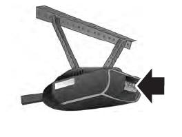
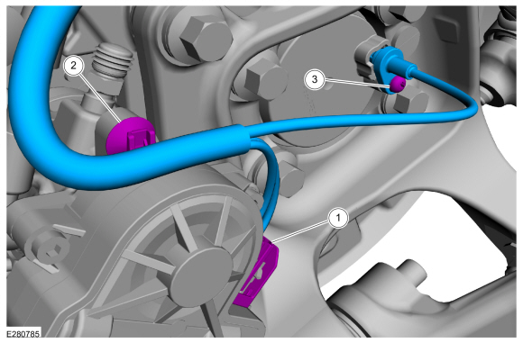
NOTICE: Route the wheel speed sensor/parking brake actuator motor harness as shown or contact with the wheel may occur causing damage to harness.
NOTE: Use the white stripe on rear wheel speed sensor harness for orientation purposes, making sure the harness is not twisted during installation.
-
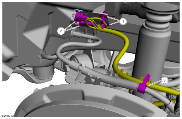
Detach the pin-type retainers.
-
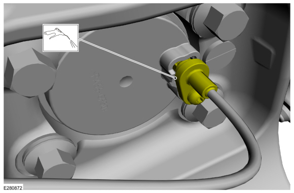
Disconnect the electrical connectors.
-
Detach the brake hose from the harness.
-
Detach the pin-type retainers.
 |
All wheel drive (AWD) vehicles
-
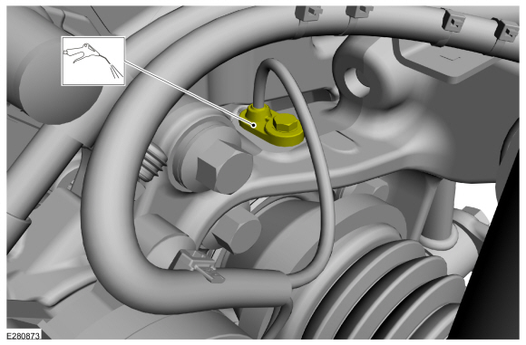
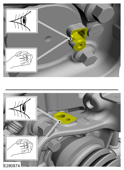
NOTE: Make sure that the sensor housing area is clean and free of foreign material before the sensor is removed.
Using compressed air, clean the sensor housing area.
 |
-
-
Disconnect the electrical connector.
-
Detach the pin-type retainer.
-
Remove the bolt and the rear wheel speed sensor.
Torque: 80 lb.in (9 Nm)
-
Disconnect the electrical connector.
 |
Front wheel drive (FWD) vehicles
-
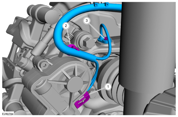
NOTE: Make sure that the sensor housing area is clean and free of foreign material before the sensor is removed.
Using compressed air, clean the sensor housing area.
 |
-
-
Disconnect the electrical connector.
-
Detach the pin-type retainer.
-
Remove the bolt and the rear wheel speed sensor.
Torque: 53 lb.in (6 Nm)
-
Disconnect the electrical connector.
 |
Installation
-
NOTICE: Before installing a new sensor, inspect the sensor housing to make sure the sensor cavity is clean and free of foreign material or damage to the sensor may occur.
Clean and inspect the sensor housing cavity.
 |
-
To install, reverse the removal procedure.
 Hydraulic Control Unit (HCU). Removal and Installation
Removal
NOTE:
Removal steps in this procedure may contain installation details.
NOTE:
The HCU and ABS module are released individually. A new HCU does not come equipped with an ABS module...

Other information:
Lincoln Nautilus 2018-2026 Service Manual: Cabin Air Filter. Removal and Installation
Removal Fully lower the glove compartment. Release the tabs. Disconnect the dampener strap. Remove the screws and open the cain air filter door. Remove the cabin air filter. Installation To install, reverse the removal procedure. ..
Lincoln Nautilus 2018-2026 Service Manual: Rear Door Tweeter Speaker. Removal and Installation
Removal All vehicles Remove the rear door trim panel. Refer to: Rear Door Trim Panel (501-05 Interior Trim and Ornamentation, Removal and Installation). Vehicles with: Harman Revel Audio System Remove the screws and the tweeter speaker through the front of the door panel. Vehicles with: AM/FM/CD/SYNC/Touchscreen Display Remove the sc..
Categories
- Manuals Home
- 1st Generation Nautilus Owners Manual
- 1st Generation Nautilus Service Manual
- Folding the Exterior Mirrors - Vehicles With: Manual Folding Mirrors. Folding the Exterior Mirrors - Vehicles With: Power Folding Mirrors
- Auto Hold
- Switching the Lane Keeping System On and Off. Switching the Lane Keeping System Mode
- New on site
- Most important about car
Programming the Garage Door Opener to Your Garage Door Opener Motor