Lincoln Nautilus: Anti-Lock Brake System (ABS) and Stability Control / Hydraulic Control Unit (HCU). Removal and Installation
Removal
NOTE: Removal steps in this procedure may contain installation details.
NOTE: The HCU and ABS module are released individually. A new HCU does not come equipped with an ABS module.
-
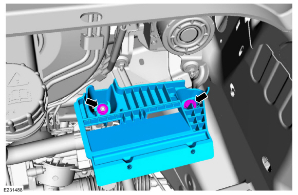
Remove the battery tray.
-
If equipped.
Remove the nut, bolt and the battery tray support bracket.
Torque: 18 lb.ft (24 Nm)
 |
-
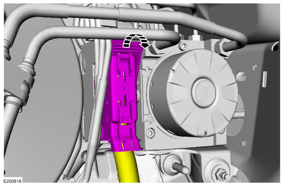
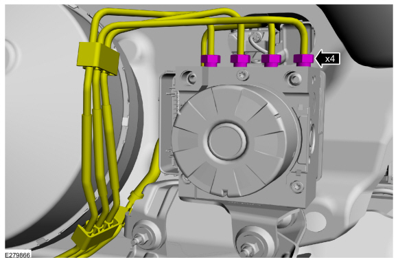
Disconnect the ABS module electrical connector.
 |
-
NOTICE: If the brake fluid is spilled on the paintwork, the affected area must be immediately washed down with cold water.
Disconnect the fittings and remove the master cylinder brake tubes.
-
Plug the brake master cylinder and HCU ports.
Torque: 18 lb.ft (25 Nm)
-
Plug the brake master cylinder and HCU ports.
 |
-
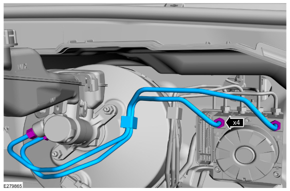
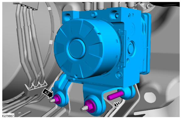
NOTICE: If the brake fluid is spilled on the paintwork, the affected area must be immediately washed down with cold water.
Disconnect the brake tube fittings.
-
Plug the HCU ports and the brake tube ends.
Torque: 17 lb.ft (23 Nm)
-
Plug the HCU ports and the brake tube ends.
 |
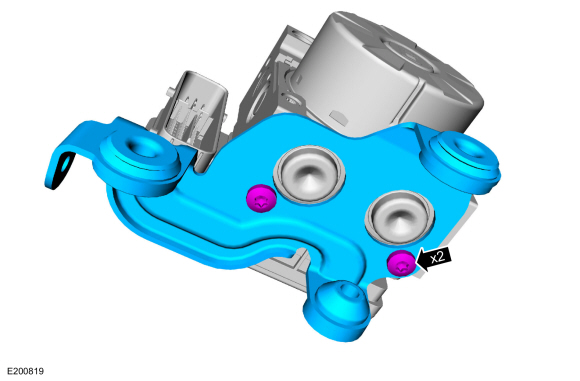
-
Remove the nuts and the HCU .
Torque: 80 lb.in (9 Nm)
 |
-
NOTE: This step is only necessary if a new HCU is being installed.
Remove the bolts and the HCU bracket.
Torque: 80 lb.in (9 Nm)
 |
-
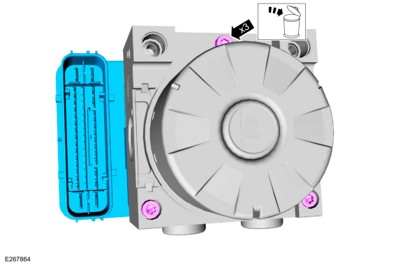
NOTICE: Make sure the HCU and ABS module are clean and free of brake fluid or foreign material before separating the components. Do not allow any brake fluid or foreign material to enter the mating side of the ABS module or component damage can occur.
Remove the screws and the ABS module. Discard the screws.
Torque: 49 lb.in (5.5 Nm)
 |
Installation
-
To install, reverse the removal procedure.
-
Bleed the brake system.
Refer to: Brake System Pressure Bleeding (206-00 Brake System - General Information, General Procedures).
-
If a new HCU
is being installed, carryout the IVD Initialization Sequence and Valve
Calibration using the scan tool and following the scan tool on-screen
instructions.
 Front Wheel Speed Sensor. Removal and Installation
Removal
NOTE:
Removal steps in this procedure may contain installation details.
Remove the wheel and tire.
Refer to: Wheel and Tire (204-04A Wheels and Tires, Removal and Installation)...
 Rear Wheel Speed Sensor. Removal and Installation
Removal
NOTE:
Removal steps in this procedure may contain installation details.
All vehicles
Remove the wheel and tire.
Refer to: Wheel and Tire (204-04A Wheels and Tires, Removal and Installation)...
Other information:
Lincoln Nautilus 2018-2026 Service Manual: Passenger Side Register Air Discharge Temperature Sensor. Removal and Installation
Removal Remove the instrument panel. Refer to: Instrument Panel (501-12 Instrument Panel and Console, Removal and Installation). Disconnect the electrical connector. Rotate and remove the sensor. Installation To install, reverse the removal procedure...
Lincoln Nautilus 2018-2026 Service Manual: Wire Terminal Inspection and Removal. General Procedures
Disconnect WARNING: Before beginning any service procedure in this section, refer to Health and Safety Precautions in section 100-00 General Information. Failure to follow this instruction may result in serious personal injury. Refer to: Health and Safety Precautions (100-00 General Information, Description and Operation)...
Categories
- Manuals Home
- 1st Generation Nautilus Owners Manual
- 1st Generation Nautilus Service Manual
- Massage Seats
- Fuel Quality
- Normal Scheduled Maintenance
- New on site
- Most important about car
Clearing the Garage Door Opener. Reprogramming the Garage Door Opener. Garage Door Opener Radio Frequencies
Clearing the Garage Door Opener