Lincoln Nautilus: Electronic Feature Group / Remote Convenience
Lincoln Nautilus 2018-2026 Service Manual / Electrical / Electronic Feature Group / Remote Convenience
- Universal Transmitter - Overview. Description and Operation
- Universal Transmitter - System Operation and Component Description. Description and Operation
- Universal Transmitter. Diagnosis and Testing
 Passive Anti-Theft System (PATS) Center Antenna. Removal and Installation
Removal
Remove the floor console.
Refer to: Floor Console (501-12 Instrument Panel and Console, Removal and Installation).
Remove the floor console bracket...
 Universal Transmitter - Overview. Description and Operation
Overview
The universal transmitter operates garage doors, gates and home or office lighting and security systems. ..
Other information:
Lincoln Nautilus 2018-2026 Owners Manual: Switching the Audio Unit On and Off. Selecting the Audio Source. Playing or Pausing the Audio Source. Adjusting the Volume
Switching the Audio Unit On and Off Press the button on the volume control. Selecting the Audio Source Audio Unit Press the button to open the media source menu. You can press this multiple times to change to the audio source or scroll through the media sources. Touchscreen Press Sources on the touchscreen to open the media source menu. Playing or Pausing the Audio Source Touchscreen Pres..
Lincoln Nautilus 2018-2026 Owners Manual: Using the Valet Mode. Using the Backup Start Passcode
Using the Valet Mode Press Settings on the touchscreen. Press Valet Mode.Note: Have your Backup Start Passcode completely setup before using Valet Mode. Note: Once the system detects a valid Phone as a Key, the temporary passcode displays in both the touchscreen and mobile app. If the system does not detect a valid Phone as a Key, it prompts you to enter your Backup Start Passcode...
Categories
- Manuals Home
- 1st Generation Nautilus Owners Manual
- 1st Generation Nautilus Service Manual
- Opening the Liftgate
- Engine Oil Capacity and Specification - 2.0L
- Locating the Pre-Collision Assist Sensors
- New on site
- Most important about car
Replacing the Rear Wiper Blades
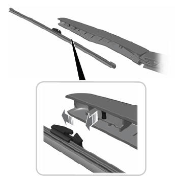
Note: Do not hold the wiper blade to lift the wiper arm.
Remove the wiper blade.Copyright © 2026 www.linautilus.com