Lincoln Nautilus: Steering Column / Steering Column - System Operation and Component Description. Description and Operation
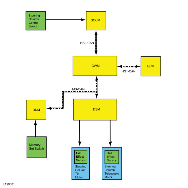
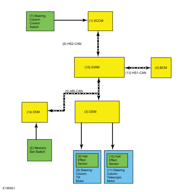
System Diagram
| Item | Description |
|---|---|
| 1 | DDM |
| 2 | SCCM |
| 3 | Memory Set Switch |
| 4 | DSM |
| 5 | BCM |
| 6 | MS-CAN |
| 7 | HS2-CAN |
| 8 | Steering Column Control Switch |
| 9 | Steering Column Tilt Motor |
| 10 | Hall Effect Sensor |
| 11 | GWM |
| 12 | Steering Column Telescopic Motor |
| 13 | Hall Effect Sensor |
| 14 | HS1-CAN |
System Operation
Network Message Chart - Power Adjustable Steering Column
Module Network Input Messages
| Broadcast Message | Originating Module | Message Purpose |
|---|---|---|
| Ignition status | BCM | This message is used to communicate ignition status, which is used for initiating the easy entry/easy exit feature. |
| Personality recall | BCM | When the personality recall command is received from the BCM , the DSM stores or recalls the steering wheel position. If a RKE transmitter has been programmed to a memory position, this input is used to recall the steering column position. |
| Steering column position switch status | SCCM | Message to control the adjustable steering column when the steering column control switch is pressed. The message is transmitted from the SCCM to the DSM via the GWM . |
| Memory seat switch status | DDM | When the memory set switch (1, 2 or 3) is activated, the DDM sends this message to the DSM which then stores or recalls the corresponding memory seat position. |
Manual Adjustable Steering Column
The manual adjustable steering column is controlled by a mechanical lever on the underside of the steering column, which uses a cam to lock and unlock the steering column. The steering column can be adjusted when the lever is pulled downward. The steering column can be adjusted up or down and in or out. When the steering column is in the desired position(s), lifting the lever upward to its original position locks the steering column.
Power Adjustable Steering Column
The power adjustable steering column is controlled by the steering column control switch, the memory SET switch or the RKE transmitter. The power adjustable steering column can be adjusted upward, downward, inward and outward using the steering column control switch.
Jog Mode
If the DSM loses the signal from either of the steering column tilt/telescopic motor sensors, the affected steering column motor operates in jog mode. Jog mode allows limited operation of the affected steering column motor using only the steering column control switch. When the steering column control switch is operated in jog mode, the steering column moves in the desired direction for one second, then stops. The steering column control switch must be released, then pressed again in order to move the steering column for an additional second. Jog mode is an indication that there is a tilt or telescoping motor sensor or circuit fault. If the adjustable steering column is operating in jog mode, a DTC sets in the DSM .
Memory Position Programming and Recall
The DSM monitors the steering column position using Hall-effect sensors that are integral to the tilt and telescopic motors. The sensors provide a digital signal used by the DSM to calculate the position of the steering column in relation to the full forward, full rearward, full up and full down positions. The DSM uses this signal to store and recall memory positions, to perform the easy entry/exit operations and to make sure the tilt and telescopic motors do not stall against the steering column end of travel. If a tilt motor sensor DTC or telescopic motor sensor (also called reach motor sensor) DTC is set, the DSM does not recall a programmed memory position or automatically position the steering column during the easy entry/easy exit operations.
The memory SET switch is monitored by the DDM . When a memory position is recalled through the memory SET switch, the DDM sends a MS-CAN message to the DSM . The DSM activates the tilt/telescopic motor(s) and monitors the Hall-effect sensors to adjust the steering column to the position that is stored in the DSM memory. Once the steering column reaches the desired position, the DSM deactivates the steering column motor(s). If the DSM receives a steering column switch input during a memory position recall function, the module stops the memory recall and responds to the new steering column switch position input.
When the RKE transmitter is activated, the BCM sends a High Speed Controller Area Network 1 (HS1-CAN) message to the GWM . The GWM then sends a MS-CAN message to the DSM , which moves the steering column to the position that is stored in the DSM memory.
DSM Hard Stop/Soft Stop
A hard stop occurs when one of the memory column axes physically reach the end of travel and can go no further. A soft stop occurs when the column stops before it physically reaches the end of travel. The hard stop is set by column design and cannot be changed or adjusted. The soft stop is set by the DSM . The memory column axes are up/down. To prevent unnecessary stress on the column and motors, the DSM sets soft stop positions, 2 for each moving axis. The DSM uses a preset distance from the hard stop to determine where the soft stop occurs. When an axis reaches the hard stop and the switch is held for approximately one second, the DSM briefly reverses direction and establishes the soft stop for that axis in that direction. The DSM uses this back up strategy to check sensor integrity any time movement has stopped prematurely due to a sensor failure or obstruction.
Easy Entry/Easy Exit
The easy entry/easy exit feature can be enabled or disabled using the message center. Refer to Driver Controls in the Owner's Literature for instructions for using the message center.
The easy entry/easy exit function moves the steering column upward when the vehicle is in the PARK position and the ignition is turned to OFF.
The DSM monitors the steering column position using Hall-effect sensors that are integral to the tilt and telescopic motors. The DSM commands the steering column upward when the ignition status message indicates the ignition is OFF. The DSM cancels this operation if a valid input is received from the steering column control switch or memory position switch.
The DSM records the current steering column position before powering the steering column for an easy exit operation. This recorded position returns the steering column to this position on the next easy entry operation (Example; The ignition is turned ON). During easy entry operation, the steering column is either returned to the position previous to the easy exit operation or to the saved memory preset if a RKE transmitter is used.
Component Description
Steering Column Control Switch
The steering column control switch is a momentary contact switch that is connected directly to the LH side of the SCCM and controls the forward, rearward, upward and downward movement of the steering column. The steering column control switch is serviced separately.
Steering Column Tilt Motor
The DSM provides power and ground to the tilt motor, which controls the upward and downward position of the power adjustable steering column. The tilt motor is equipped with a Hall-effect type rotation sensor that sends digital signals to the DSM . The DSM uses these signals to calculate the location of the steering column in relation to the full up and down positions and to make sure the tilt motor does not stall against the steering column end of travel in the up or down direction. The tilt motor is serviced separately from the steering column.
Steering Column Telescopic Motor
The DSM provides power and ground to the telescopic motor, which controls the inward and outward position of the power adjustable steering column. The telescopic motor is equipped with a Hall-effect type rotation sensor that sends digital signals to the DSM . The DSM uses these signals to calculate the location of the steering column in relation to the full forward and rearward positions and to make sure the telescopic motor does not stall against the steering column end of travel in the forward or rearward direction. The telescopic motor is serviced with the steering column.
Steering Effort Control Module (vehicles equipped with adaptive steering)
The steering wheel contains the Steering Effort Control Module (SECM), which provides power and ground to the adaptive steering motor.
The SECM cannot be serviced independently. It is only replaced as an assembly with the steering wheel.
The SECM requires PMI when replaced.
 Steering Column - Overview. Description and Operation
Steering Column Overview
The steering column system consists of the following components:
Steering wheel
SCCM
Telescopic and tilt motors (power adjustable steering column)
Steering column control switch (power adjustable steering column)
The
steering column is the mechanical linkage between the steering wheel
and the steering gear...
 Steering Column. Diagnosis and Testing
DTC Chart: SCCM
Diagnostics in this manual assume a certain skill level and knowledge of Ford-specific diagnostic practices. REFER to: Diagnostic Methods (100-00 General Information, Description and Operation)...
Other information:
Lincoln Nautilus 2018-2026 Service Manual: Rear Door Window Regulator and Motor. Removal and Installation
Removal NOTE: LH side shown, RH side similar. NOTE: Removal steps in this procedure may contain installation details. Remove the rear door trim panel. Refer to: Rear Door Trim Panel (501-05 Interior Trim and Ornamentation, Removal and Installation)...
Lincoln Nautilus 2018-2026 Service Manual: Audio Digital Signal Processing (DSP) Module. Removal and Installation
Removal NOTE: Removal steps in this procedure may contain installation details. NOTE: If installing a new module, it is necessary to upload the module configuration information to the scan tool prior to removing the module. This information must be downloaded into the new module after installation...
Categories
- Manuals Home
- 1st Generation Nautilus Owners Manual
- 1st Generation Nautilus Service Manual
- Normal Scheduled Maintenance
- Programming the Garage Door Opener to Your Garage Door Opener Motor
- Auto-Start-Stop
- New on site
- Most important about car
Replacing the Rear Wiper Blades
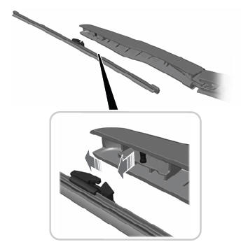
Note: Do not hold the wiper blade to lift the wiper arm.
Remove the wiper blade.