Lincoln Nautilus: Steering Wheel and Column Electrical Components / Steering Wheel and Column Electrical Components. Diagnosis and Testing
DTC Charts
Diagnostics in this manual assume a certain skill level and knowledge of Ford-specific diagnostic practices.
REFER to: Diagnostic Methods (100-00 General Information, Description and Operation).
BCM DTC Chart
| DTC | Description | Action |
|---|---|---|
| B108A:01 | Start Button: General Electrical Failure | GO to Pinpoint Test A |
| B108A:24 | Start Button: Signal Stuck High | GO to Pinpoint Test A |
| B108A:9E | Start Button: Stuck On | GO to Pinpoint Test A |
| B1142:29 | Ignition Status 1: Signal Invalid | GO to Pinpoint Test A |
| B1240:11 | Start Button Mode Indicator: Circuit Short to Ground | GO to Pinpoint Test B |
| B1240:15 | Start Button Mode Indicator: Circuit Short to Battery or Open |
|
| B130F:12 | Run Accessory Control: Circuit Short to Battery |
REFER to: Wipers and Washers (501-16 Wipers and Washers, Diagnosis and Testing). |
| B130F:14 | Run Accessory Control: Circuit Short to Ground or Open |
REFER to: Wipers and Washers (501-16 Wipers and Washers, Diagnosis and Testing). |
| B1310:12 | Run/Start Control: Circuit Short to Battery | GO to Pinpoint Test A |
| B1310:14 | Run/Start Control: Circuit Short to Ground or Open | GO to Pinpoint Test A |
| U300A:01 | Ignition Switch: General Electrical Failure | GO to Pinpoint Test A |
| All other Diagnostic Trouble Codes (DTCs) | - |
REFER to: Body Control Module (BCM) (419-10 Multifunction Electronic Modules, Diagnosis and Testing). |
Diagnostics in this manual assume a certain skill level and knowledge of Ford-specific diagnostic practices.
REFER to: Diagnostic Methods (100-00 General Information, Description and Operation).
SCCM DTC Chart
| DTC | Description | Action |
|---|---|---|
| B1007:09 | High-Beam Headlamp Switch: Component Failure |
REFER to: Headlamps (417-01 Exterior Lighting, Diagnosis and Testing). |
| B1008:09 | Wiper Mode Switch: Component Failure |
REFER to: Wipers and Washers (501-16 Wipers and Washers, Diagnosis and Testing). |
| B1051:09 | Front Washer Switch: Component Failure |
REFER to: Wipers and Washers (501-16 Wipers and Washers, Diagnosis and Testing). |
| B1052:09 | Rear Washer Switch: Component Failure |
REFER to: Wipers and Washers (501-16 Wipers and Washers, Diagnosis and Testing). |
| B10AD:02 | Rain Sensor: General Signal Failure |
REFER to: Wipers and Washers (501-16 Wipers and Washers, Diagnosis and Testing). |
| B10AD:08 | Rain Sensor: Bus Signal/Message Failure |
REFER to: Wipers and Washers (501-16 Wipers and Washers, Diagnosis and Testing). |
| B10AD:49 | Rain Sensor: Internal Electronic Failure |
REFER to: Wipers and Washers (501-16 Wipers and Washers, Diagnosis and Testing). |
| B10AD:55 | Rain Sensor: Not Configured |
REFER to: Wipers and Washers (501-16 Wipers and Washers, Diagnosis and Testing). |
| B1131:02 | Wiper motor module: General Signal Failure |
REFER to: Wipers and Washers (501-16 Wipers and Washers, Diagnosis and Testing). |
| B1131:08 | Wiper motor module: Bus Signal/Message Failure |
REFER to: Wipers and Washers (501-16 Wipers and Washers, Diagnosis and Testing). |
| B1131:11 | Wiper motor module: Circuit Short To Ground |
REFER to: Wipers and Washers (501-16 Wipers and Washers, Diagnosis and Testing). |
| B1131:49 | Wiper motor module: Internal Electronic Failure |
REFER to: Wipers and Washers (501-16 Wipers and Washers, Diagnosis and Testing). |
| B1131:55 | Wiper motor module: Not Configured |
REFER to: Wipers and Washers (501-16 Wipers and Washers, Diagnosis and Testing). |
| B1131:9A | Wiper motor module: Component or System Operating Conditions |
REFER to: Wipers and Washers (501-16 Wipers and Washers, Diagnosis and Testing). |
| B11D9:16 | Vehicle Battery: Circuit Voltage Below Threshold | GO to Pinpoint Test D |
| B11D9:17 | Vehicle Battery: Circuit Voltage Above Threshold | GO to Pinpoint Test E |
| B1298:09 | Steering Column Adjust Up Switch: Component Failure |
REFER to: Steering Column (211-04 Steering Column, Diagnosis and Testing). |
| B1299:09 | Steering Column Adjust Down Switch: Component Failure |
REFER to: Steering Column (211-04 Steering Column, Diagnosis and Testing). |
| B12A1:09 | Steering Column Adjust Out Switch: Component Failure |
REFER to: Steering Column (211-04 Steering Column, Diagnosis and Testing). |
| B12A2:09 | Steering Column Adjust In Switch: Component Failure |
REFER to: Steering Column (211-04 Steering Column, Diagnosis and Testing). |
| B12F7:09 | Single Wipe Switch: Component Failure |
REFER to: Wipers and Washers (501-16 Wipers and Washers, Diagnosis and Testing). |
| B137F:09 | Steering Wheel Left Switch Pack: Component Failure |
REFER to: Cruise Control (419-03A Cruise Control, Diagnosis and Testing). REFER to: Cruise Control (419-03B Cruise Control - Vehicles With: Adaptive Cruise Control With Lane Centering, Diagnosis and Testing). |
| B137F:11 | Steering Wheel Left Switch Pack: Circuit Short to Ground |
REFER to: Cruise Control (419-03A Cruise Control, Diagnosis and Testing). REFER to: Cruise Control (419-03B Cruise Control - Vehicles With: Adaptive Cruise Control With Lane Centering, Diagnosis and Testing). |
| B137F:17 | Steering Wheel Left Switch Pack: Circuit Voltage Above Threshold |
REFER to: Cruise Control (419-03A Cruise Control, Diagnosis and Testing). REFER to: Cruise Control (419-03B Cruise Control - Vehicles With: Adaptive Cruise Control With Lane Centering, Diagnosis and Testing). |
| B1380:09 | Steering Wheel Right Switch Pack: Component Failure | Refer to the appropriate section in Group 415 for the procedure. |
| B1380:11 | Steering Wheel Right Switch Pack: Circuit Short to Ground | Refer to the appropriate section in Group 415 for the procedure. |
| B1380:17 | Steering Wheel Right Switch Pack: Circuit Voltage Above Threshold | Refer to the appropriate section in Group 415 for the procedure. |
| B13A6:09 | Lane Departure Warning (LDW) Switch Input: Component Failure |
REFER to: Lane Keeping System (419-07 Lane Keeping System, Diagnosis and Testing). |
| B1D36:09 | Turn Indicator Switch: Component Failure |
REFER to: Turn Signal and Hazard Lamps (417-01 Exterior Lighting, Diagnosis and Testing). |
| C1B00:09 | Steering Angle Sensor: Component Failure |
REFER to: Anti-Lock Brake System (ABS) and Stability Control (206-09 Anti-Lock Brake System (ABS) and Stability Control, Diagnosis and Testing). |
| C1B00:29 | Steering Angle Sensor: Signal Invalid |
REFER to: Anti-Lock Brake System (ABS) and Stability Control (206-09 Anti-Lock Brake System (ABS) and Stability Control, Diagnosis and Testing). |
| U0121:00 | Lost Communication With Anti-Lock Brake System (ABS) Control Module: No Sub Type Information | GO to Pinpoint Test F |
| U0415:00 | Invalid Data Received From Anti-Lock Brake System (ABS) Control Module: No Sub Type Information |
DIAGNOSE all non-network Diagnostic Trouble Codes (DTCs) in the ABS module. REFER to: Anti-Lock Brake System (ABS) and Stability Control (206-09 Anti-Lock Brake System (ABS) and Stability Control, Diagnosis and Testing). |
| U2100:00 | Initial Configuration Not Complete: No Sub Type Information |
Check vehicle service history for recent service actions related to
this module. This DTC can set due to incomplete or improper PMI
procedures. If there have been recent service actions with this module,
REPEAT/CARRY OUT the PMI
procedure as directed by the diagnostic scan tool. If there have been
no recent service actions, INSTALL a new module to correct the failure
to retain configuration data. REFER to: Steering Column Control Module (SCCM) (211-05 Steering Wheel and Column Electrical Components, Removal and Installation). REFER to: Steering Column Control Module (SCCM) - Vehicles With: Adaptive Steering (211-05 Steering Wheel and Column Electrical Components, Removal and Installation). |
| U2101:00 | Control Module Configuration Incompatible: No Sub Type Information | This DTC sets if the steering wheel switches do not match the switch function configuration data in the SCCM . CHECK the parts catalog and CONFIRM that the correct SCCM and steering wheel control switches are installed in the vehicle. INSTALL the correct components, as necessary. |
| U3000:49 | Control Module: Internal Electronic Failure |
INSTALL a new SCCM . REFER to: Steering Column Control Module (SCCM) - Vehicles With: Adaptive Steering (211-05 Steering Wheel and Column Electrical Components, Removal and Installation). |
Diagnostics in this manual assume a certain skill level and knowledge of Ford-specific diagnostic practices.
REFER to: Diagnostic Methods (100-00 General Information, Description and Operation).
HSWM DTC Chart
| DTC | Description | Action |
|---|---|---|
| B135C:11 | Heater Element: Circuit Short to Ground | GO to Pinpoint Test H |
| B135C:15 | Heater Element: Circuit Short to Battery or Open | GO to Pinpoint Test H |
| U0100:00 | Lost Communication With ECM/PCM "A": No Sub Type Operation | GO to Pinpoint Test I |
| U0140:00 | Lost Communication With Body Control Module: No Sub Type Operation | GO to Pinpoint Test J |
| U0256:00 | Lost Communication With Front Controls Interface Module "A": No Sub Type Operation | GO to Pinpoint Test K |
| U1000:00 | Solid State Driver Protection Active - Driver Disabled: No Sub Type Operation | The HSWM has temporarily disabled an output because an excessive current draw exists (such as a short to ground). The HSWM cannot enable the output until the cause of the short is corrected. ADDRESS all other Diagnostic Trouble Codes (DTCs) first. After the cause of the concern is corrected, CLEAR the Diagnostic Trouble Codes (DTCs). REPEAT the self-test. |
| U2100:00 | Initial Configuration Not Complete: No Sub Type Operation | This DTC sets due to incomplete or improper PMI procedures. CARRY OUT the PMI procedure as directed by the diagnostic scan tool. Use As-Built data when carrying out PMI for this DTC . |
| U210A:11 | Temperature Sensor: Circuit Short to Ground | GO to Pinpoint Test L |
| U210A:15 | Temperature Sensor: Circuit Short to Battery or Open | GO to Pinpoint Test L |
| U3000:49 | Control Module: Internal Electronic Failure |
INSTALL a new HSWM . REFER to: Heated Steering Wheel Module (HSWM) (211-05 Steering Wheel and Column Electrical Components, Removal and Installation). |
Diagnostics in this manual assume a certain skill level and knowledge of Ford-specific diagnostic practices.
REFER to: Diagnostic Methods (100-00 General Information, Description and Operation).
SECM DTC Chart
| DTC | Description | Action |
|---|---|---|
| B135C:11 | Heater Element: Circuit Short to Ground |
CLEAR the DTC . REPEAT the self-test. If DTC B135C:11 is retrieved again, REFER to: Steering Wheel - Vehicles With: Adaptive Steering (211-04 Steering Column, Removal and Installation). |
| B135C:15 | Heater Element: Circuit Short to Battery or Open |
CLEAR the DTC . REPEAT the self-test. If DTC B135C:15 is retrieved again, REFER to: Steering Wheel - Vehicles With: Adaptive Steering (211-04 Steering Column, Removal and Installation). |
| U1000:00 | Solid State Driver Protection Active - Driver Disabled: No Sub Type Operation |
CLEAR the DTC . REPEAT the self-test. If DTC U1000:00 is retrieved again, REFER to: Steering Wheel - Vehicles With: Adaptive Steering (211-04 Steering Column, Removal and Installation). |
| U210A:11 | Temperature Sensor: Circuit Short To Ground |
CLEAR the DTC . REPEAT the self-test. If DTC U210A:11 is retrieved again, REFER to: Steering Wheel - Vehicles With: Adaptive Steering (211-04 Steering Column, Removal and Installation). |
| U210A:15 | Temperature Sensor: Circuit Short To Battery or Open |
CLEAR the DTC . REPEAT the self-test. If DTC U210A:15 is retrieved again, REFER to: Steering Wheel - Vehicles With: Adaptive Steering (211-04 Steering Column, Removal and Installation). |
| All other Diagnostic Trouble Codes (DTCs) | - |
REFER to: Adaptive Steering (211-02 Power Steering, Diagnosis and Testing). |
Symptom Charts
Symptom Chart: Ignition Switch - Push Button
Diagnostics in this manual assume a certain skill level and knowledge of Ford-specific diagnostic practices.
REFER to: Diagnostic Methods (100-00 General Information, Description and Operation).
Symptom Chart
| Condition | Possible Causes | Actions |
|---|---|---|
| No power in ON |
|
|
| Key not detected displays in the message center |
|
|
| The ignition mode indicator is inoperative |
|
|
| The ignition mode indicator is always on |
|
|
Symptom Chart: Heated Steering Wheel (vehicles not equipped with adaptive steering)
Diagnostics in this manual assume a certain skill level and knowledge of Ford-specific diagnostic practices.
REFER to: Diagnostic Methods (100-00 General Information, Description and Operation).
Symptom Chart
| Condition | Possible Causes | Actions |
|---|---|---|
| The heated steering wheel is inoperative or does not operate correctly |
|
|
Symptom Chart: Heated Steering Wheel (vehicles equipped with adaptive steering)
Diagnostics in this manual assume a certain skill level and knowledge of Ford-specific diagnostic practices.
REFER to: Diagnostic Methods (100-00 General Information, Description and Operation).
Symptom Chart
| Condition | Possible Causes | Actions |
|---|---|---|
| The heated steering wheel is inoperative or does not operate correctly |
|
|
Pinpoint Tests
No Power in ON - Push Button Ignition Switch
Refer to Wiring Diagrams Cell 13 for schematic and connector information.
Refer to Wiring Diagrams Cell 20 for schematic and connector information.
Normal Operation and Fault Conditions
REFER to: Steering Wheel and Column Electrical Components - System
Operation and Component Description (211-05 Steering Wheel and Column
Electrical Components, Description and Operation).
BCM DTC Fault Trigger Conditions
| DTC | Description | Fault Trigger Conditions |
|---|---|---|
| B108A:01 | Start Button: General Electrical Failure | Sets continuous when the BCM detects a fault from one of the ignition switch input circuits. |
| B108A:24 | Start Button: Signal Stuck High | Sets continuous when the BCM detects a fault from one of the ignition switch input circuits. |
| B108A:9E | Start Button: Stuck On | Sets continuous when the BCM detects only one switch input circuit indicating open when the start button is released. |
| B1142:29 | Ignition Status 1: Signal Invalid | Sets during the on-demand self-test when the BCM detects a fault from one of the ignition switch input circuits. |
| U300A:01 | Ignition Switch: General Electrical Failure | Sets when the BCM detects an invalid combination from the ignition switch input circuits. |
Possible Causes
- Battery voltage concern
- Fuse
- Wiring, terminals or connectors
- Relay
- BJB
- PATS concern
- GSM
- BCM
Visual Inspection and Diagnostic Pre-checks
- Inspect the battery and battery cables.
- Inspect the BCM fuse 7 (10A) and F20 (5A).
PINPOINT TEST A: NO POWER IN ON - PUSH BUTTON IGNITION SWITCH
| NOTICE: Use the correct probe adapter(s) when making measurements. Failure to use the correct probe adapter(s) may damage the connector. | ||||||||||||||||
| A1 CHECK THE VEHICLE BATTERY | ||||||||||||||||
Is the battery OK?
|
||||||||||||||||
| A2 CHECK FOR IGNITION ON MODE | ||||||||||||||||
Does the ignition mode indicator flash on and off continuously?
|
||||||||||||||||
| A3 CHECK FOR A PATS (PASSIVE ANTI-THEFT SYSTEM) CONCERN | ||||||||||||||||
Does No key detected display in the message center?
|
||||||||||||||||
| A4 CHECK THE IGNITION SWITCH 1 (START_STOP_1) PID (PARAMETER IDENTIFICATION) | ||||||||||||||||
Does the PID change state when the START/STOP button is pressed and released?
|
||||||||||||||||
| A5 CHECK THE GSM (GEAR SHIFT MODULE) POWER CIRCUITS FOR VOLTAGE. | ||||||||||||||||
Is the voltage greater than 11 volts?
|
||||||||||||||||
| A6 CHECK THE GSM (GEAR SHIFT MODULE) POWER CIRCUITS FOR AN OPEN. | ||||||||||||||||
Is the resistance less than 3 ohms?
|
||||||||||||||||
| A7 CHECK THE START/STOP 1 INPUT CIRCUIT FOR A SHORT TO VOLTAGE | ||||||||||||||||
Is any voltage present?
|
||||||||||||||||
| A8 CHECK THE START/STOP 1 INPUT CIRCUIT FOR A SHORT TO THE START/STOP 2 INPUT CIRCUIT | ||||||||||||||||
Is the resistance greater than 10,000 ohms?
|
||||||||||||||||
| A9 CHECK THE START/STOP 1 INPUT CIRCUIT FOR A SHORT TO GROUND | ||||||||||||||||
Is the resistance greater than 10,000 ohms?
|
||||||||||||||||
| A10 BYPASS THE PUSH BUTTON IGNITION SWITCH WHILE MONITORING THE IGNITION SWITCH 1 (START_STOP_1) PID (PARAMETER IDENTIFICATION) | ||||||||||||||||
Does the PID indicate the START/STOP button is pressed with the fused jumper wire connected?
|
||||||||||||||||
| A11 CHECK FOR VOLTAGE TO THE IGNITION SWITCH | ||||||||||||||||
Is the voltage greater than 11 volts?
|
||||||||||||||||
| A12 CHECK THE IGNITION SWITCH VOLTAGE SUPPLY CIRCUIT FOR AN OPEN | ||||||||||||||||
Is the resistance less than 3 ohms?
|
||||||||||||||||
| A13 CHECK THE BCM (BODY CONTROL MODULE) START/STOP 1 INPUT CIRCUIT FOR AN OPEN | ||||||||||||||||
Is the resistance less than 3 ohms?
|
||||||||||||||||
| A14 CHECK THE IGNITION SWITCH 2 (START_STOP_2) PID (PARAMETER IDENTIFICATION) | ||||||||||||||||
Does the PID change state when the START/STOP button is pressed and released?
|
||||||||||||||||
| A15 CHECK THE BCM (BODY CONTROL MODULE) START/STOP 2 INPUT CIRCUIT FOR A SHORT TO VOLTAGE | ||||||||||||||||
Is any voltage present?
|
||||||||||||||||
| A16 CHECK THE START/STOP 1 INPUT CIRCUIT FOR A SHORT TO THE START/STOP 2 INPUT CIRCUIT | ||||||||||||||||
Is the resistance greater than 10,000 ohms?
|
||||||||||||||||
| A17 CHECK THE BCM (BODY CONTROL MODULE) START/STOP 2 INPUT CIRCUIT FOR A SHORT TO GROUND | ||||||||||||||||
Is the resistance greater than 10,000 ohms?
|
||||||||||||||||
| A18 BYPASS THE PUSH BUTTON IGNITION SWITCH WHILE MONITORING THE IGNITION SWITCH 2 (START_STOP_2) PID (PARAMETER IDENTIFICATION) | ||||||||||||||||
Does the PID indicate the START/STOP button is pressed with the fused jumper wire connected?
|
||||||||||||||||
| A19 CHECK THE IGNITION SWITCH GROUND CIRCUITS FOR AN OPEN | ||||||||||||||||
Is the voltage greater than 11 volts?
|
||||||||||||||||
| A20 CHECK THE BCM (BODY CONTROL MODULE) START/STOP 2 INPUT CIRCUIT FOR AN OPEN | ||||||||||||||||
Is the resistance less than 3 ohms?
|
||||||||||||||||
| A21 CARRY OUT A NETWORK TEST | ||||||||||||||||
Does the GSM and the BCM pass the network test?
|
||||||||||||||||
| A22 CHECK THE BJB (BATTERY JUNCTION BOX) RUN/START RELAY | ||||||||||||||||
Is the concern still present?
|
||||||||||||||||
| A23 CHECK THE BJB (BATTERY JUNCTION BOX) RUN/START RELAY VOLTAGE SUPPLY | ||||||||||||||||
Are the voltages greater than 11 volts?
|
||||||||||||||||
| A24 CHECK THE BCM (BODY CONTROL MODULE) RUN/START RELAY CONTROL | ||||||||||||||||
|
NOTE: The following step uses a test lamp to simulate normal circuit loads. Use only a Rotunda Test Lamp (SGT27000) or 250- 300mA incandescent bulb test lamp. To avoid connector terminal damage, use the Rotunda Flex Probe kit for the test lamp probe connection to the vehicle. Do not use the test lamp probe directly on any connector.
Does the test lamp illuminate?
|
||||||||||||||||
| A25 CHECK THE BCM (BODY CONTROL MODULE) RUN/START RELAY CONTROL CIRCUIT TO THE BJB (BATTERY JUNCTION BOX) | ||||||||||||||||
|
NOTE: The following step uses a test lamp to simulate normal circuit loads. Use only a Rotunda Test Lamp (SGT27000) or 250- 300mA incandescent bulb test lamp. To avoid connector terminal damage, use the Rotunda Flex Probe kit for the test lamp probe connection to the vehicle. Do not use the test lamp probe directly on any connector.
Does the test lamp illuminate?
|
||||||||||||||||
| A26 CHECK THE BCM (BODY CONTROL MODULE) RUN/START RELAY CONTROL CIRCUIT FOR A SHORT TO GROUND | ||||||||||||||||
Is the resistance greater than 10,000 ohms?
|
||||||||||||||||
| A27 CHECK THE BCM (BODY CONTROL MODULE) RUN/START RELAY CONTROL CIRCUIT FOR AN OPEN | ||||||||||||||||
Is the resistance less than 3 ohms?
|
||||||||||||||||
| A28 CHECK FOR CORRECT GSM (GEAR SHIFT MODULE) OPERATION | ||||||||||||||||
Is the concern still present?
|
||||||||||||||||
| A29 CHECK FOR CORRECT BCM (BODY CONTROL MODULE) OPERATION | ||||||||||||||||
Is the concern still present?
|


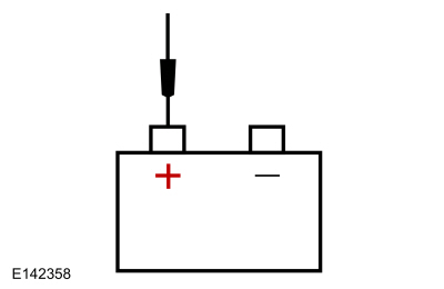 Battery Positive Terminal
The Ignition Mode Indicator Is Inoperative
Refer to Wiring Diagrams Cell 20 for schematic and connector information.
Normal Operation and Fault Conditions
REFER to: Steering Wheel and Column Electrical Components - System
Operation and Component Description (211-05 Steering Wheel and Column
Electrical Components, Description and Operation).
BCM DTC Fault Trigger Conditions
| DTC | Description | Fault Trigger Conditions |
|---|---|---|
| B1240:11 | Start Button Mode Indicator: Circuit Short to Ground | Sets when the BCM detects a short to ground from the ignition mode status indicator circuit. |
| B1240:15 | Start Button Mode Indicator: Circuit Short to Battery or Open | Sets when the BCM detects an open from the ignition mode status indicator circuit. |
Possible Causes
- Wiring, terminals or connectors
- GSM
- BCM
PINPOINT TEST B: THE IGNITION MODE INDICATOR IS INOPERATIVE
| NOTICE: Use the correct probe adapter(s) when making measurements. Failure to use the correct probe adapter(s) may damage the connector. | ||||||||||||||||
| B1 CHECK FOR VOLTAGE TO THE IGNITION MODE INDICATOR | ||||||||||||||||
Is the voltage greater than 11 volts?
|
||||||||||||||||
| B2 CHECK THE IGNITION MODE INDICATOR VOLTAGE CIRCUIT FOR A SHORT TO GROUND | ||||||||||||||||
Is the resistance greater than 10,000 ohms?
|
||||||||||||||||
| B3 CHECK THE IGNITION MODE INDICATOR VOLTAGE CIRCUIT FOR AN OPEN | ||||||||||||||||
Is the resistance less than 3 ohms?
|
||||||||||||||||
| B4 CHECK THE IGNITION MODE INDICATOR GROUND CIRCUITS FOR AN OPEN | ||||||||||||||||
Is the voltage greater than 11 volts?
|
||||||||||||||||
| B5 CHECK FOR CORRECT GSM (GEAR SHIFT MODULE) OPERATION | ||||||||||||||||
Is the concern still present?
|
||||||||||||||||
| B6 CHECK FOR CORRECT BCM (BODY CONTROL MODULE) OPERATION | ||||||||||||||||
Is the concern still present?
|
The Ignition Mode Indicator Is Always On
Refer to Wiring Diagrams Cell 20 for schematic and connector information.
Normal Operation and Fault Conditions
REFER to: Steering Wheel and Column Electrical Components - System
Operation and Component Description (211-05 Steering Wheel and Column
Electrical Components, Description and Operation).
BCM DTC Fault Trigger Conditions
| DTC | Description | Fault Trigger Conditions |
|---|---|---|
| B1240:15 | Start Button Mode Indicator: Circuit Short to Battery or Open | Sets when the BCM detects a short to voltage from the ignition mode status indicator circuit. |
Possible Causes
- Wiring, terminals or connectors
- GSM
- BCM
PINPOINT TEST C: THE IGNITION MODE INDICATOR IS ALWAYS ON
| NOTICE: Use the correct probe adapter(s) when making measurements. Failure to use the correct probe adapter(s) may damage the connector. | ||||||||||
| C1 ISOLATE THE BCM (BODY CONTROL MODULE) | ||||||||||
Does the ignition mode indicator continue to illuminate?
|
||||||||||
| C2 CHECK THE IGNITION MODE INDICATOR CIRCUIT FOR A SHORT TO VOLTAGE | ||||||||||
Is any voltage present?
|
||||||||||
| C3 CHECK FOR CORRECT GSM (GEAR SHIFT MODULE) OPERATION | ||||||||||
Is the concern still present?
|
||||||||||
| C4 CHECK FOR CORRECT BCM (BODY CONTROL MODULE) OPERATION | ||||||||||
Is the concern still present?
|
B11D9:16
Refer to Wiring Diagrams Cell 13 for schematic and connector information.
Normal Operation and Fault Conditions
The SCCM continuously monitors input voltage for correct operation. If voltage outside of defined limits is detected by the SCCM , the applicable DTC sets. DTC B11D9:16 can set if the vehicle battery has been discharged. The vehicle battery may become discharged due to excessive load(s) on the charging system from aftermarket accessories or if the vehicle has been left unattended with the accessories on.
SCCM DTC Fault Trigger Conditions
| DTC | Description | Fault Trigger Conditions |
|---|---|---|
| B11D9:16 | Vehicle Battery: Circuit Below Threshold | Sets in continuous memory if the SCCM detects battery voltage below 8 volts on the battery voltage supply circuit. |
Possible Causes
- Battery
- Wiring, terminals or connectors
- Fuse
- Charging system
- SCCM
Visual Inspection and Diagnostic Pre-checks
- Make sure the vehicle battery terminals and cables are free of any corrosion and other contaminates.
- Make sure the vehicle battery terminals are tightened to their correct torque specifications.
PINPOINT TEST D: B11D9:16
| NOTICE: Use the correct probe adapter(s) when making measurements. Failure to use the correct probe adapter(s) may damage the connector. | ||||||||||
| D1 CHECK FOR SCCM (STEERING COLUMN CONTROL MODULE) DIAGNOSTIC TROUBLE CODES (DTCS) | ||||||||||
Is DTC B11D9:16 still present?
|
||||||||||
| D2 CHECK FOR CHARGING SYSTEM DIAGNOSTIC TROUBLE CODES (DTCS) IN THE PCM (POWERTRAIN CONTROL MODULE) | ||||||||||
Are any charging system Diagnostic Trouble Codes (DTCs) present in the PCM ?
|
||||||||||
| D3 CHECK THE BATTERY CONDITION AND STATE OF CHARGE | ||||||||||
Is the battery OK?
|
||||||||||
| D4 CHECK THE SCCM (STEERING COLUMN CONTROL MODULE) VOLTAGE SUPPLY CIRCUIT FOR HIGH RESISTANCE | ||||||||||
Is the voltage within 0.2 volt of the recorded battery voltage?
|
||||||||||
| D5 CHECK THE SCCM (STEERING COLUMN CONTROL MODULE) GROUND CIRCUIT FOR HIGH RESISTANCE | ||||||||||
Is the resistance less than 3 ohms?
|
||||||||||
| D6 CHECK FOR CORRECT SCCM (STEERING COLUMN CONTROL MODULE) OPERATION | ||||||||||
Is the concern still present?
|
B11D9:17
Refer to Wiring Diagrams Cell 13 for schematic and connector information.
Normal Operation and Fault Conditions
The SCCM continuously monitors input voltage for correct operation. If voltage outside of defined limits is detected by the SCCM , the applicable DTC sets. DTC B11D9:17 can set if the vehicle has been recently jump started or the vehicle battery has been recently charged.
SCCM DTC Fault Trigger Conditions
| DTC | Description | Fault Trigger Conditions |
|---|---|---|
| B11D9:17 | Vehicle Battery: Circuit Above Threshold | Sets in continuous memory if the SCCM detects battery voltage above 19 volts on the battery voltage supply circuit. |
Possible Causes
- Wiring, terminals or connectors
- Charging system
- SCCM
PINPOINT TEST E: B11D9:17
| E1 CHECK FOR HIGH BATTERY VOLTAGE AND/OR CHARGING SYSTEM DTC (DIAGNOSTIC TROUBLE CODE) IN THE PCM (POWERTRAIN CONTROL MODULE) | ||||
Are any voltage and/or charging system Diagnostic Trouble Codes (DTCs) present?
|
||||
| E2 CHECK THE BATTERY VOLTAGE | ||||
Does the battery voltage rise to 16.5 volts or higher?
|
||||
| E3 RECHECK FOR SCCM (STEERING COLUMN CONTROL MODULE) DTC (DIAGNOSTIC TROUBLE CODE) B11D9:17 | ||||
Is DTC B11D9:17 still present?
|
||||
| E4 CHECK FOR CORRECT SCCM (STEERING COLUMN CONTROL MODULE) OPERATION | ||||
Is the concern still present?
|
U0121:00
Refer to Wiring Diagrams Cell 128 for schematic and connector information.
Normal Operation and Fault Conditions
The SCCM communicates with the ABS module over the CAN . If the SCCM does not receive messages from the ABS module, no noticeable symptom may be present.
SCCM DTC Fault Trigger Conditions
| DTC | Description | Fault Trigger Conditions |
|---|---|---|
| U0121:00 | Lost Communication With Anti-Lock Brake System (ABS) Control Module: No Sub Type Information | Sets when the SCCM does not receive an expected message from the ABS module for more than 5 seconds. |
Possible Causes
- Network communication concern
- ABS module
PINPOINT TEST F: U0121:00
| F1 VERIFY THE CUSTOMER CONCERN | ||||
Is an observable symptom present?
|
||||
| F2 CHECK THE COMMUNICATION NETWORK | ||||
Does the ABS module pass the network test?
|
||||
| F3 CHECK FOR NON-NETWORK ABS (ANTI-LOCK BRAKE SYSTEM) MODULE DIAGNOSTIC TROUBLE CODES (DTCS) | ||||
Are any non-network Diagnostic Trouble Codes (DTCs) present?
|
||||
| F4 CHECK FOR NON-NETWORK SCCM (STEERING COLUMN CONTROL MODULE) DIAGNOSTIC TROUBLE CODES (DTCS) | ||||
Are any non-network Diagnostic Trouble Codes (DTCs) present?
|
||||
| F5 RECHECK THE SCCM (STEERING COLUMN CONTROL MODULE) DIAGNOSTIC TROUBLE CODES (DTCS) | ||||
|
NOTE: If new modules were installed prior to the DTC being set, the module configuration may be incorrectly set during PMI or PMI may not have been carried out
Is DTC U0121:00 still present?
|
||||
| F6 CHECK FOR OTHER CAUSES OF COMMUNICATION NETWORK CONCERN | ||||
Is the observable symptom still present?
|
||||
| F7 CHECK FOR CORRECT ABS (ANTI-LOCK BRAKE SYSTEM) MODULE OPERATION | ||||
Is the concern still present?
|
The Heated Steering Wheel Is Inoperative Or Does Not Operate Correctly
Refer to Wiring Diagrams Cell 128 for schematic and connector information.
Normal Operation and Fault Conditions
When steering wheel heat is requested and the engine is running, the HSWM uses a sensor in the steering wheel (integral to the steering wheel) to maintain the heated steering wheel temperature. The resistance of the sensor rises as the temperature falls and the resistance falls as the temperature rises. The resistance can vary from 3,384 ohms at 50°C (122°F) to 34,699 ohms at 0°C (32°F). The HSWM supplies a reference voltage and ground to the temperature sensor and monitors the voltage drop from the temperature sensor for controlling current flow to the heating element. The HSWM is designed to remain on, heating the steering wheel and maintaining temperature until switched OFF using the FCIM or the ignition is turned OFF.
NOTE: On all vehicles, slow heating between the 10 o'clock and 2 o'clock steering wheel hand positions is considered normal.
Possible Causes
- Wiring, terminals or connectors
- Steering wheel
- Clockspring
- HSWM
PINPOINT TEST G: THE HEATED STEERING WHEEL IS INOPERATIVE OR DOES NOT OPERATE CORRECTLY
| NOTICE: Use the correct probe adapter(s) when making measurements. Failure to use the correct probe adapter(s) may damage the connector. | ||||||||||||||||||||||||||
| G1 CHECK FOR COMMUNICATION TO THE HSWM (HEATED STEERING WHEEL MODULE) | ||||||||||||||||||||||||||
Does the HSWM pass the network test?
|
||||||||||||||||||||||||||
| G2 CHECK FOR HSWM (HEATED STEERING WHEEL MODULE) DIAGNOSTIC TROUBLE CODES (DTCS) | ||||||||||||||||||||||||||
Are any Diagnostic Trouble Codes (DTCs) present?
|
||||||||||||||||||||||||||
| G3 CHECK THE HEATER ELEMENT TEMPERATURE SENSOR AND CIRCUIT RESISTANCE | ||||||||||||||||||||||||||
Is the resistance within the specified value for the current temperature of the steering wheel?
|
||||||||||||||||||||||||||
| G4 CHECK THE HEATER ELEMENT TEMPERATURE SENSOR CIRCUITS RESISTANCE TO THE CLOCKSPRING | ||||||||||||||||||||||||||
Are the resistances less than 3 ohms?
|
||||||||||||||||||||||||||
| G5 CHECK THE HEATER ELEMENT TEMPERATURE SENSOR RESISTANCE | ||||||||||||||||||||||||||
Is the resistance within the specified value for the current temperature of the steering wheel?
|
||||||||||||||||||||||||||
| G6 VERIFY THE SRS (SUPPLEMENTAL RESTRAINT SYSTEM) PROVES OUT SUCCESSFULLY | ||||||||||||||||||||||||||
Did the SRS prove out successfully?
|
||||||||||||||||||||||||||
| G7 CHECK FOR CORRECT HSWM (HEATED STEERING WHEEL MODULE) OPERATION | ||||||||||||||||||||||||||
Is the concern still present?
|
B135C:11, B135C:15
Refer to Wiring Diagrams Cell 128 for schematic and connector information.
Normal Operation and Fault Conditions
When steering wheel heat is requested and the engine is running, the HSWM applies voltage and ground to the steering wheel heating element (integral to the steering wheel). The steering wheel heating element draws between 1 and 10 amps of current depending on steering wheel temperature. The HSWM uses a sensor in the steering wheel (integral to the steering wheel) to maintain the heated steering wheel temperature. The HSWM is designed to remain on, heating the steering wheel and maintaining temperature until switched OFF using the FCIM or the ignition is turned OFF.
HSWM DTC Fault Trigger Conditions
| DTC | Description | Fault Trigger Conditions |
|---|---|---|
| B135C:11 | Heater Element: Circuit Short to Ground | Sets when the heated steering wheel is commanded on and the HSWM senses current greater than 10 amps from the steering wheel heating element output circuit, indicating a short to ground or when the steering wheel heating element output Field Effect Transistor (FET) in the HSWM has a thermal failure. When this fault sets, the steering wheel heating element output is disabled until the ignition is cycled. |
| B135C:15 | Heater Element: Circuit Short to Battery or Open | Sets when the heated steering wheel is commanded on and the module senses current less than 1 amp from the steering wheel heating element output circuit. This indicates a short to voltage, an open circuit or an open in the heating element. When this fault sets, the steering wheel heating element output is disabled until the ignition is cycled. |
Possible Causes
- Wiring, terminals or connectors
- Steering wheel
- Clockspring
- HSWM
PINPOINT TEST H: B135C:11, B135C:15
| NOTICE: Use the correct probe adapter(s) when making measurements. Failure to use the correct probe adapter(s) may damage the connector. | |||||||||||||
| H1 CHECK THE HSWM (HEATED STEERING WHEEL MODULE) DIAGNOSTIC TROUBLE CODES (DTCS) | |||||||||||||
Is DTC B135C:11 present?
|
|||||||||||||
| H2 CHECK THE HEATER ELEMENT VOLTAGE CIRCUIT FOR A SHORT TO GROUND | |||||||||||||
Is the resistance greater than 10,000 ohms?
|
|||||||||||||
| H3 CHECK THE HEATER ELEMENT VOLTAGE CIRCUIT TO THE CLOCKSPRING FOR A SHORT TO GROUND | |||||||||||||
Is the resistance greater than 10,000 ohms?
|
|||||||||||||
| H4 CHECK THE HEATER ELEMENT FOR A SHORT TO GROUND | |||||||||||||
Is the resistance greater than 10,000 ohms?
|
|||||||||||||
| H5 CHECK THE HEATER ELEMENT AND RETURN CIRCUIT RESISTANCE | |||||||||||||
Is the resistance between 1.6 and 3.1 ohms?
|
|||||||||||||
| H6 CHECK THE HEATER ELEMENT CIRCUITS FOR A SHORT TOGETHER | |||||||||||||
Is the resistance greater than 10,000 ohms?
|
|||||||||||||
| H7 CHECK THE HEATER ELEMENT FOR AN INTERNAL SHORT | |||||||||||||
Is the resistance between 1.6 and 3.1 ohms?
|
|||||||||||||
| H8 CHECK THE HEATER ELEMENT VOLTAGE AND GROUND CIRCUITS FOR A SHORT TO VOLTAGE | |||||||||||||
Is any voltage present?
|
|||||||||||||
| H9 CHECK THE HEATER ELEMENT AND CIRCUIT RESISTANCE | |||||||||||||
Is the resistance between 1.6 and 3.1 ohms?
|
|||||||||||||
| H10 CHECK THE HEATER ELEMENT CIRCUITS FOR AN OPEN | |||||||||||||
Are the resistances less than 3 ohms?
|
|||||||||||||
| H11 CHECK THE HEATER ELEMENT RESISTANCE | |||||||||||||
Is the resistance between 1.6 and 3.1 ohms?
|
|||||||||||||
| H12 CHECK FOR CORRECT HSWM (HEATED STEERING WHEEL MODULE) OPERATION | |||||||||||||
Is the concern still present?
|
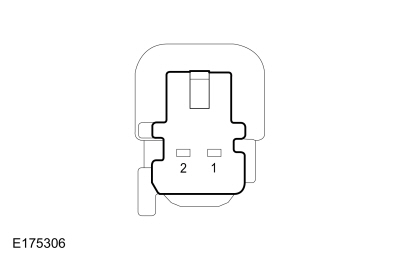 C218D, pin 2 (steering wheel side)
U0100:00
Normal Operation and Fault Conditions
The HSWM communicates with the PCM over the CAN through the GWM . If the HSWM does not receive messages from the PCM , no noticeable symptom may be present.
HSWM DTC Fault Trigger Conditions
| DTC | Description | Fault Trigger Conditions |
|---|---|---|
| U0100:00 | Lost Communication With ECM/PCM "A": No Sub Type Information | Sets when the HSWM does not receive an expected message from the PCM for more than 5 seconds. |
Possible Causes
- Network communication concern
- PCM
PINPOINT TEST I: U0100:00
| I1 VERIFY THE CUSTOMER CONCERN | ||||
Is an observable symptom present?
|
||||
| I2 CHECK THE COMMUNICATION NETWORK | ||||
Does the PCM pass the network test?
|
||||
| I3 CHECK FOR NON-NETWORK PCM (POWERTRAIN CONTROL MODULE) DIAGNOSTIC TROUBLE CODES (DTCS) | ||||
Are any non-network Diagnostic Trouble Codes (DTCs) present?
|
||||
| I4 CHECK FOR NON-NETWORK HSWM (HEATED STEERING WHEEL MODULE) DIAGNOSTIC TROUBLE CODES (DTCS) | ||||
Are any non-network Diagnostic Trouble Codes (DTCs) present?
|
||||
| I5 RECHECK THE HSWM (HEATED STEERING WHEEL MODULE) DIAGNOSTIC TROUBLE CODES (DTCS) | ||||
|
NOTE: If new modules were installed prior to the DTC being set, the module configuration may be incorrectly set during PMI or PMI may not have been carried out
Is DTC U0100:00 still present?
|
||||
| I6 CHECK FOR OTHER CAUSES OF COMMUNICATION NETWORK CONCERN | ||||
Is the observable symptom still present?
|
||||
| I7 CHECK FOR CORRECT PCM (POWERTRAIN CONTROL MODULE) OPERATION | ||||
Is the concern still present?
|

 VIN required to access Guided Routine (PCM)
U0140:00
Normal Operation and Fault Conditions
The HSWM communicates with the BCM over the CAN . If the HSWM does not receive messages from the BCM , no noticeable symptom may be present.
HSWM DTC Fault Trigger Conditions
| DTC | Description | Fault Trigger Conditions |
|---|---|---|
| U0140:00 | Lost Communication With Body Control Module: No Sub Type Information | Sets when the HSWM does not receive an expected message from the BCM for more than 5 seconds. |
Possible Causes
- Network communication concern
- BCM
PINPOINT TEST J: U0140:00
| J1 VERIFY THE CUSTOMER CONCERN | ||||
Is an observable symptom present?
|
||||
| J2 CHECK THE COMMUNICATION NETWORK | ||||
Does the BCM pass the network test?
|
||||
| J3 CHECK FOR NON-NETWORK BCM (BODY CONTROL MODULE) DIAGNOSTIC TROUBLE CODES (DTCS) | ||||
Are any non-network Diagnostic Trouble Codes (DTCs) present?
|
||||
| J4 CHECK FOR NON-NETWORK HSWM (HEATED STEERING WHEEL MODULE) DIAGNOSTIC TROUBLE CODES (DTCS) | ||||
Are any non-network Diagnostic Trouble Codes (DTCs) present?
|
||||
| J5 RECHECK THE HSWM (HEATED STEERING WHEEL MODULE) DIAGNOSTIC TROUBLE CODES (DTCS) | ||||
|
NOTE: If new modules were installed prior to the DTC being set, the module configuration may be incorrectly set during PMI or PMI may not have been carried out
Is DTC U0140:00 still present?
|
||||
| J6 CHECK FOR OTHER CAUSES OF COMMUNICATION NETWORK CONCERN | ||||
Is the observable symptom still present?
|
||||
| J7 CHECK FOR CORRECT BCM (BODY CONTROL MODULE) OPERATION | ||||
Is the concern still present?
|
U0256:00
Normal Operation and Fault Conditions
The HSWM communicates with the FCIM over the CAN . If the HSWM does not receive messages from the FCIM , the heated steering wheel function can be inoperative.
HSWM DTC Fault Trigger Conditions
| DTC | Description | Fault Trigger Conditions |
|---|---|---|
| U0256:00 | Lost Communication With Front Controls Interface Module "A": No Sub Type Information | Sets when the HSWM does not receive an expected message from the FCIM for more than 5 seconds. |
Possible Causes
- Network communication concern
- FCIM
PINPOINT TEST K: U0256:00
| K1 VERIFY THE CUSTOMER CONCERN | ||||
Is an observable symptom present?
|
||||
| K2 CHECK THE COMMUNICATION NETWORK | ||||
Does the FCIM pass the network test?
|
||||
| K3 CHECK FOR NON-NETWORK FCIM (FRONT CONTROLS INTERFACE MODULE) DIAGNOSTIC TROUBLE CODES (DTCS) | ||||
Are any non-network Diagnostic Trouble Codes (DTCs) present?
|
||||
| K4 CHECK FOR NON-NETWORK HSWM (HEATED STEERING WHEEL MODULE) DIAGNOSTIC TROUBLE CODES (DTCS) | ||||
Are any non-network Diagnostic Trouble Codes (DTCs) present?
|
||||
| K5 RECHECK THE HSWM (HEATED STEERING WHEEL MODULE) DIAGNOSTIC TROUBLE CODES (DTCS) | ||||
|
NOTE: If new modules were installed prior to the DTC being set, the module configuration may be incorrectly set during PMI or PMI may not have been carried out
Is DTC U0256:00 still present?
|
||||
| K6 CHECK FOR OTHER CAUSES OF COMMUNICATION NETWORK CONCERN | ||||
Is the observable symptom still present?
|
||||
| K7 CHECK FOR CORRECT FCIM (FRONT CONTROLS INTERFACE MODULE) OPERATION | ||||
Is the concern still present?
|
U210A:11, U210A:15
Refer to Wiring Diagrams Cell 128 for schematic and connector information.
Normal Operation and Fault Conditions
When steering wheel heat is requested and the engine is running, the HSWM uses a sensor in the steering wheel (integral to the steering wheel) to maintain the heated steering wheel temperature. The resistance of the sensor rises as the temperature falls and the resistance falls as the temperature rises. The resistance can vary from 3,384 ohms at 50°C (122°F) to 34,699 ohms at 0°C (32°F). The HSWM supplies a reference voltage and ground to the temperature sensor and monitors the voltage drop from the temperature sensor for controlling current flow to the heating element. The HSWM is designed to remain on, heating the steering wheel and maintaining temperature, until switched OFF using the FCIM or the ignition is turned OFF.
HSWM DTC Fault Trigger Conditions
| DTC | Description | Fault Trigger Conditions |
|---|---|---|
| U210A:11 | Temperature Sensor: Circuit Short to Ground | Sets when the heated steering wheel is commanded on and the HSWM reads a resistance value less than 627 ohms on the heating element temperature sensor input circuit, indicating a short to ground. When this fault occurs, the steering wheel heating element output is disabled until the ignition is cycled. |
| U210A:15 | Temperature Sensor: Circuit Short to Battery or Open | Sets when the heated steering wheel is commanded on and the HSWM reads a resistance value greater than 670,000 ohms on the heating element temperature sensor reference circuit for greater than 10 minutes. This indicates a short to voltage, an open circuit or an open heating element temperature sensor. When this fault occurs, the steering wheel heating element output is disabled until the ignition is cycled. |
Possible Causes
- Wiring, terminals or connectors
- Steering wheel
- Clockspring
- HSWM
PINPOINT TEST L: U210A:11, U210A:15
| NOTICE: Use the correct probe adapter(s) when making measurements. Failure to use the correct probe adapter(s) may damage the connector. | |||||||||||||
| L1 CHECK THE HSWM (HEATED STEERING WHEEL MODULE) DIAGNOSTIC TROUBLE CODES (DTCS) | |||||||||||||
Is DTC U210A:11 present?
|
|||||||||||||
| L2 CHECK THE HEATER ELEMENT TEMPERATURE SENSOR REFERENCE CIRCUIT FOR A SHORT TO GROUND | |||||||||||||
Is the resistance greater than 10,000 ohms?
|
|||||||||||||
| L3 CHECK THE HEATER ELEMENT TEMPERATURE SENSOR REFERENCE CIRCUIT TO THE CLOCKSPRING FOR A SHORT TO GROUND | |||||||||||||
Is the resistance greater than 10,000 ohms?
|
|||||||||||||
| L4 CHECK THE HEATER ELEMENT TEMPERATURE SENSOR FOR A SHORT TO GROUND | |||||||||||||
Is the resistance greater than 10,000 ohms?
|
|||||||||||||
| L5 CHECK THE HEATER ELEMENT TEMPERATURE SENSOR AND CIRCUIT FOR LOW RESISTANCE | |||||||||||||
Is the resistance greater than 627 ohms?
|
|||||||||||||
| L6 CHECK THE HEATER ELEMENT TEMPERATURE SENSOR CIRCUITS FOR A SHORT TOGETHER | |||||||||||||
Is the resistance greater than 10,000 ohms?
|
|||||||||||||
| L7 CHECK THE HEATER ELEMENT TEMPERATURE SENSOR FOR A SHORT | |||||||||||||
Is the resistance greater than 627 ohms?
|
|||||||||||||
| L8 CHECK THE HEATER ELEMENT TEMPERATURE SENSOR REFERENCE AND GROUND CIRCUITS FOR A SHORT TO VOLTAGE | |||||||||||||
Is any voltage present?
|
|||||||||||||
| L9 CHECK THE HEATER ELEMENT TEMPERATURE SENSOR AND CIRCUIT FOR HIGH RESISTANCE | |||||||||||||
Is the resistance less than 670,000 ohms?
|
|||||||||||||
| L10 CHECK THE HEATER ELEMENT TEMPERATURE SENSOR CIRCUITS FOR AN OPEN | |||||||||||||
Are the resistances less than 3 ohms?
|
|||||||||||||
| L11 CHECK THE HEATER ELEMENT TEMPERATURE SENSOR FOR HIGH RESISTANCE | |||||||||||||
Is the resistance less than 670,000 ohms?
|
|||||||||||||
| L12 VERIFY THE SRS (SUPPLEMENTAL RESTRAINT SYSTEM) PROVES OUT SUCCESSFULLY | |||||||||||||
Did the SRS prove out successfully?
|
|||||||||||||
| L13 CHECK FOR CORRECT HSWM (HEATED STEERING WHEEL MODULE) OPERATION | |||||||||||||
Is the concern still present?
|

 Steering Column Multifunction Switch Adjustment. General Procedures
Adjustment
Using a diagnostic scan tool, retrieve and diagnose all SECM Diagnostic Trouble Codes (DTCs).
Refer to: Adaptive Steering (211-02 Power Steering, Diagnosis and Testing)...
Other information:
Lincoln Nautilus 2018-2026 Owners Manual: Remote Control Limitations
WARNING: Changes or modifications not expressively approved by the party responsible for compliance could void the user's authority to operate the equipment. The term "IC:" before the radio certification number only signifies that Industry Canada technical specifications were met...
Lincoln Nautilus 2018-2026 Owners Manual: Phone as a Key – Troubleshooting
Phone as a Key – Frequently Asked Questions How can I tell if my vehicle has Phone as a Key? The touchscreen shows the Phone as a Key reset option if your vehicle has Phone as a Key. If you have registered your vehicle through the Lincoln Way app, a control button appears on the home screen of the Lincoln Way app...
Categories
- Manuals Home
- 1st Generation Nautilus Owners Manual
- 1st Generation Nautilus Service Manual
- Programming the Garage Door Opener to Your Garage Door Opener Motor
- Replacing the Rear Wiper Blades
- Opening the Liftgate
- New on site
- Most important about car
Replacing the Rear Wiper Blades
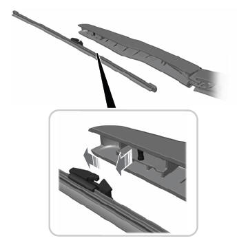
Note: Do not hold the wiper blade to lift the wiper arm.
Remove the wiper blade.