Lincoln Nautilus Manuals

Lincoln Nautilus: Accessory Charging / Wireless Accessory Charging Module (WACM). Diagnosis and Testing

Lincoln Nautilus 2018-2024 Service Manual / Electrical / Battery and Charging System / Accessory Charging / Wireless Accessory Charging Module (WACM). Diagnosis and Testing

Diagnostic Trouble Code (DTC) Chart

Diagnostics in this manual assume a certain skill level and knowledge of Ford-specific diagnostic practices.
REFER to: Diagnostic Methods (100-00 General Information, Description and Operation).


Module DTC Description Action
APIM U0253:00 Lost Communication With Accessory Protocol Interface Module: No Sub Type Information GO to Pinpoint Test E
BCM B1554:11 Wireless Accessory Charger Enable/Disable: Circuit Short To Ground GO to Pinpoint Test A
BCM B1554:13 Wireless Accessory Charger Enable/Disable: Circuit Open GO to Pinpoint Test A
WACM U0140:00 Lost Communication With Body Control Module: No Sub Type Information GO to Pinpoint Test D
WACM U0184:00 Lost Communication With Radio: No Sub Type Information GO to Pinpoint Test F
WACM U201A:51 Control Module Main Calibration Data: Not Programmed GO to Pinpoint Test H
WACM U2100:00 Initial Configuration Not Complete: No Sub Type Information GO to Pinpoint Test H
WACM U2101:00 Control Module Configuration Incompatible: No Sub Type Information GO to Pinpoint Test H
WACM U3000:41 Control Module: General Checksum Failure GO to Pinpoint Test G
WACM U3000:42 Control Module: General Memory Failure GO to Pinpoint Test G
WACM U3000:49 Control Module: Internal Electronic Failure GO to Pinpoint Test G
WACM U3003:16 Battery Voltage: Circuit Voltage Below Threshold GO to Pinpoint Test C
WACM U3003:17 Battery Voltage: Circuit Voltage Above Threshold GO to Pinpoint Test C

Global Customer Symptom Code (GCSC) Chart

Diagnostics in this manual assume a certain skill level and knowledge of Ford-specific diagnostic practices.
REFER to: Diagnostic Methods (100-00 General Information, Description and Operation).


Symptom Action
Driver Aid & Information > Power/Charge Port/Pad > Performance > Inoperative GO to Pinpoint Test B

Symptom Chart(s)

Diagnostics in this manual assume a certain skill level and knowledge of Ford-specific diagnostic practices.
REFER to: Diagnostic Methods (100-00 General Information, Description and Operation).

Symptom Chart: WACM (Wireless Accessory Charging Module)


Condition Possible Sources Actions
A module does not communicate with the diagnostic scan tool
  • Fuse(s)
  • Wiring, terminals or connectors
  • ACM
  • APIM
  • BCM
  • WACM
 
REFER to: Controller Area Network (CAN) Module Communications Network (418-00A Controller Area Network (CAN) Module Communications Network, Diagnosis and Testing).
The WACM Cannot Be Controlled Or Could Always Be On REFER to Pinpoint Test   GO to Pinpoint Test A
The WACM Is Inoperative REFER to Pinpoint Test   GO to Pinpoint Test B

Pinpoint Test(s)


PINPOINT TEST A: B1554:11, B1554:13

Refer to Wiring Diagrams Cell 44 for schematic and connector information.

Normal Operation and Fault Conditions

REFER to: Wireless Accessory Charging Module (WACM) - System Operation and Component Description (414-06 Accessory Charging, Description and Operation).

DTC Fault Trigger Conditions

DTC Description Fault Trigger Condition
BCM B1554:11 Wireless Accessory Charger Enable/Disable: Circuit Short To Ground This DTC sets when the module senses lower than expected voltage on the WACM hardwired status circuit, indicating a short to ground. The primary method of configuring WACM off during an interior key search may not work; the CAN signal backup is the only mechanism to prevent WACM from interfering with an interior key search.
BCM B1554:13 Wireless Accessory Charger Enable/Disable: Circuit Open This DTC sets when the module senses no voltage on the WACM hardwired status circuit, indicating an open circuit. The primary method of configuring WACM off during an interior key search may not work; the CAN signal backup is the only mechanism to prevent WACM from interfering with an interior key search.

Possible Sources

  • Wiring, terminals or connectors
  • WACM

Visual Inspection and Pre-checks

  • Recheck wireless charging process with a known good smart phone that contains the built-in wireless charging technology. Or test wireless charging process with a cell phone with a wireless-capable back cover or adapter.
  • With a known compatible cell phone resting on the WACM pad, monitor the FCIM (if equipped) or IPC message center (if equipped) for the WACM charging status message "Wireless Charger Active". This message displays after a cell phone has been laid on the charging pad and started a wireless charging session (may only appear on first charging session of a given ignition cycle). A recheck of this message can be performed by turning the ignition off, then back on, then placing the compatible phone back on the charging pad.
  • The "Charge Terminated" message will typically appear within 25 seconds after a foreign object /phone misaligned is detected on the charging pad.
  • Inspect for loose or corroded WACM connections.
  • Remind customer that only compatible phones with built-in wireless charging or with a compatible wireless charging case can be used with the charger.

NOTICE: Use the correct probe adapter(s) when making measurements. Failure to use the correct probe adapter(s) may damage the connector.

A1 CHECK THE WACM (WIRELESS ACCESSORY CHARGING MODULE) OPERATION
  • Place a known compliant cell phone onto the WACM charging pad.
  • Observe for the "Wireless Charger Active" message to display through the FCIM (if equipped) or IPC message center (if equipped).

Does the charging pad operate?
Yes REFER to Owner’s Literature for proper use and operation.
No GO to A2

A2 CHECK THE COMMUNICATION NETWORK
  • Ignition ON.
  • Using a diagnostic scan tool, carry out the network test.

Does the WACM pass the network test?
Yes GO to A3
No DIAGNOSE the WACM does not communicate with the diagnostic scan tool.
REFER to: Controller Area Network (CAN) Module Communications Network (418-00A Controller Area Network (CAN) Module Communications Network, Diagnosis and Testing).

A3 CHECK THE BCM (BODY CONTROL MODULE) WACM (WIRELESS ACCESSORY CHARGING MODULE) STATUS CIRCUIT FOR A SHORT TO VOLTAGE
  • Ignition OFF.
  • Disconnect BCM C2280G .
  • Disconnect WACM C3853 .
  • Ignition ON.
  • Measure:
    Click to display connectors
    Positive Lead Measurement / Action Negative Lead
      C2280G-11   Ground

Is there any voltage present?
Yes REPAIR the circuit.
No GO to A4

A4 CHECK THE BCM (BODY CONTROL MODULE) WACM (WIRELESS ACCESSORY CHARGING MODULE) STATUS CIRCUIT FOR A SHORT TO GROUND
  • Measure:
    Click to display connectors
    Positive Lead Measurement / Action Negative Lead
      C2280G-11   Ground

Are the resistances greater than 10,000 ohms?
Yes GO to A5
No REPAIR the circuit.

A5 CHECK THE BCM (BODY CONTROL MODULE) WACM (WIRELESS ACCESSORY CHARGING MODULE) STATUS CIRCUIT FOR AN OPEN
  • Disconnect BCM C2280G .
  • Disconnect WACM C3853 .
  • Measure:
    Click to display connectors
    Positive Lead Measurement / Action Negative Lead
      C3853-3   C2280G-11

Are the resistances less than 3 ohms?
Yes GO to A6
No REPAIR the circuit.

A6 CHECK THE WACM (WIRELESS ACCESSORY CHARGING MODULE) VBAT CIRCUIT AND WACM (WIRELESS ACCESSORY CHARGING MODULE) STATUS CIRCUIT FOR A SHORT TOGETHER
  • Measure:
    Click to display connectors
    Positive Lead Measurement / Action Negative Lead
      C2280G-11   C2280F-29

Are the resistances greater than 10,000 ohms?
Yes GO to A7
No REPAIR the circuit.

A7 CHECK FOR CORRECT BCM (BODY CONTROL MODULE) OPERATION
  • Ignition OFF.
  • Disconnect and inspect all the BCM connectors.
  • Repair:
    • corrosion (install new connector or terminals – clean module pins)
    • damaged or bent pins – install new terminals/pins
    • pushed-out pins – install new pins as necessary
  • Reconnect all BCM connectors. Make sure they seat and latch correctly.
  • Operate the system and determine if the concern is still present.

Is the concern still present?
Yes CHECK OASIS for any applicable service articles: TSB , GSB , SSM or FSA . If a service article exists for this concern, DISCONTINUE this test and FOLLOW the service article instructions. If no service articles address this concern, Install a new BCM .
REFER to: Wireless Accessory Charging Module (WACM) (414-06 Accessory Charging, Removal and Installation).
No The system is operating correctly at this time. The concern may have been caused by a loose or corroded connector. ADDRESS the root cause of any connector or pin issues.

PINPOINT TEST B: THE WACM (WIRELESS ACCESSORY CHARGING MODULE) IS INOPERATIVE

NOTE: There may be intermittent passive engine start attempts if the wireless charging feature is in use and the remote key FOB is placed in close proximity to the wireless charger.


Refer to Wiring Diagrams Cell 44 for schematic and connector information.

Normal Operation and Fault Conditions

REFER to: Wireless Accessory Charging Module (WACM) - System Operation and Component Description (414-06 Accessory Charging, Description and Operation).

Possible Sources

  • Wiring, terminals or connectors
  • Environmental Interference
  • WACM

Visual Inspection and Pre-checks

  • Recheck wireless charging process with a known good smart phone that contains the built-in wireless charging technology. Or test wireless charging process with a cell phone with a wireless-capable back cover or adapter. Verify phone charges for at least 30 seconds. It is recommended to place the cell phone as close to the center of the charging surface as possible and to use a cell phone with a battery state of charge of less than 80 percent.
  • With a known compatible cell phone resting on the WACM pad, monitor the FCIM (if equipped) or IPC message center (if equipped) for the WACM charging status message "Wireless Charger Active". This message displays after a cell phone has been laid on the charging pad and started a wireless charging session (may only appear on first charging session of a given ignition cycle). A recheck of this message can be performed by turning the ignition off, then back on, then placing the compatible phone back on the charging pad.
  • The "Charge Terminated" message will typically appear within 25 seconds after a foreign object /phone misaligned is detected on the charging pad.
  • Inspect for loose or corroded WACM connections.
  • Remind customer that only compatible phones with built-in wireless charging or with a compatible wireless charging case can be used with the charger.

NOTICE: Use the correct probe adapter(s) when making measurements. Failure to use the correct probe adapter(s) may damage the connector.

B1 CHECK FOR WACM (WIRELESS ACCESSORY CHARGING MODULE) DTCS (DIAGNOSTIC TROUBLE CODES)
  • Ignition ON.
  • Using a diagnostic scan tool, carry out the WACM self-test.

Are any diagnostic trouble codes (DTCs) present?
Yes GO to B2
No REFER to Owner’s Manual for proper use and operation.

B2 CHECK THE COMMUNICATION NETWORK
  • Ignition ON.
  • Using a diagnostic scan tool, carry out the network test.

Does the WACM pass the network test?
Yes GO to B3
No DIAGNOSE the WACM does not communicate with the diagnostic scan tool.
REFER to: Controller Area Network (CAN) Module Communications Network (418-00A Controller Area Network (CAN) Module Communications Network, Diagnosis and Testing).

B3 CHECK THE WACM (WIRELESS ACCESSORY CHARGING MODULE) STATUS CIRCUIT FOR A SHORT TO VOLTAGE
  • Ignition OFF.
  • Disconnect BCM C2280G .
  • Disconnect Wireless Accessory Charging Module C3853 .
  • Ignition ON.
  • Measure:
    Click to display connectors
    Positive Lead Measurement / Action Negative Lead
      C3853-3   Ground

Is there any voltage present?
Yes REPAIR the circuit.
No GO to B4

B4 CHECK THE WACM (WIRELESS ACCESSORY CHARGING MODULE) STATUS CIRCUIT FOR A SHORT TO GROUND
  • Measure:
    Click to display connectors
    Positive Lead Measurement / Action Negative Lead
      C3853-3   Ground

Are the resistances greater than 10,000 ohms?
Yes GO to B5
No REPAIR the circuit.

B5 CHECK THE BCM (BODY CONTROL MODULE) WACM (WIRELESS ACCESSORY CHARGING MODULE) STATUS CIRCUIT FOR AN OPEN
  • Disconnect BCM C2280G .
  • Disconnect WACM C3853 .
  • Measure:
    Click to display connectors
    Positive Lead Measurement / Action Negative Lead
      C3853-3   C2280G-11

Are the resistances less than 3 ohms?
Yes GO to B6
No REPAIR the circuit.

B6 CHECK THE WACM (WIRELESS ACCESSORY CHARGING MODULE) VBAT CIRCUIT AND WACM (WIRELESS ACCESSORY CHARGING MODULE) STATUS CIRCUIT FOR A SHORT TOGETHER
  • Measure:
    Click to display connectors
    Positive Lead Measurement / Action Negative Lead
      C3853-1   C3853-3

Are the resistances greater than 10,000 ohms?
Yes GO to B7
No REPAIR the circuit.

B7 CHECK FOR CORRECT WACM (WIRELESS ACCESSORY CHARGING MODULE) OPERATION
  • Ignition OFF.
  • Disconnect and inspect all the WACM connectors.
  • Repair:
    • corrosion (install new connector or terminals – clean module pins)
    • damaged or bent pins – install new terminals/pins
    • pushed-out pins – install new pins as necessary
  • Reconnect all WACM connectors. Make sure they seat and latch correctly.
  • Operate the system and determine if the concern is still present.

Is the concern still present?
Yes CHECK OASIS for any applicable service articles: TSB , GSB , SSM or FSA . If a service article exists for this concern, DISCONTINUE this test and FOLLOW the service article instructions. If no service articles address this concern, INSTALL a new WACM .
REFER to: Wireless Accessory Charging Module (WACM) (414-06 Accessory Charging, Removal and Installation).
No The system is operating correctly at this time. The concern may have been caused by a loose or corroded connector. ADDRESS the root cause of any connector or pin issues.

PINPOINT TEST C: U3003:16, U3003:17

Refer to Wiring Diagrams Cell 12 for schematic and connector information.

Normal Operation and Fault Conditions

The WACM requires an operating voltage that is between 9 and 15.5 volts. The WACM receives this voltage from the BCM . The WACM has a single ground circuit located in the passenger compartment wiring harness. Excessive resistance or an open in one or more of these circuits, a discharged battery, and overcharging condition or a inoperative charging system results in the WACM setting a DTC .

DTC Fault Trigger Conditions

DTC Description Fault Trigger Condition
WACM U3003:16 Battery Voltage: Circuit Voltage Below Threshold Sets in the WACM if it detects battery voltage below 9 volts on the voltage supply circuit for 2.5 seconds or longer.
WACM U3003:17 Battery Voltage: Circuit Voltage Above Threshold Sets in the WACM if it detects battery voltage above 15.5 volts on the voltage supply circuit for 2.5 seconds or longer.

Possible Sources

  • Fuses
  • Wiring, terminals or connectors
  • Charging system concern
  • Battery
  • WACM

Visual Inspection and Pre-checks

  • Make sure the vehicle battery terminals and cables are free of any corrosion and other contaminants.
  • Make sure the vehicle battery terminals are tightened to their correct torque specifications.
  • Make sure BCM power fuse (7.5A) is OK.
  • Inspect for loose or corroded WACM connections.

NOTE: DTC U3003:17 may be stored in the module memory due to past battery charging or vehicle jump starting events.

Use the correct probe adapter(s) when making measurements. Failure to use the correct probe adapter(s) may cause damage to the connector.
C1 CARRY OUT THE WACM (WIRELESS ACCESSORY CHARGING MODULE) SELF-TEST
  • Start the engine.
  • Using a diagnostic scan tool, perform the WACM self-test.
  • Using a diagnostic scan tool, clear the WACM Diagnostic Trouble Codes (DTCs).
  • Ignition OFF.
  • Wait 10 seconds.
  • Start the engine.
  • Using a diagnostic scan tool, perform the WACM self-test.

Is DTC U3003:16 or U3003:17 still present?
Yes GO to C2
No The system is operating normally at this time. The DTC may have been set previously during battery charging or while jump starting the vehicle.

C2 : CHECK THE BATTERY CONDITION AND STATE OF CHARGE
  • Carry out the Battery Condition Test diagnostic routine.
    REFER to: Battery (414-01 Battery, Mounting and Cables, Diagnosis and Testing).

Did the battery pass the condition test?
Yes GO to C3
No INSTALL a new battery. REFER to Group 414-01 for the appropriate battery replacement procedure.
REFER to: Battery (414-01 Battery, Mounting and Cables, Removal and Installation).

C3 CHECK THE CHARGING SYSTEM VOLTAGE

NOTE: Do not allow the engine Revolutions Per Minute (RPM) to exceed 2,000 Revolutions Per Minute (RPM) while carrying out this step or the generator may self-excite, resulting in default charging system output voltage. If engine Revolutions Per Minute (RPM) exceeds 2,000 Revolutions Per Minute (RPM), shut the vehicle off and restart the engine before carrying out this step.

  • Start the engine.
  • Measure:
    Click to display connectors
    Positive Lead Measurement / Action Negative Lead

Does the battery voltage rise above 15.5 volts or higher?
Yes For DTC U3003:17, DIAGNOSE the charging system. REFER to Group 414-00 for the appropriate charging system diagnosis and testing procedure.
No For DTC U3003:16, GO to C4

C4 CHECK THE WACM (WIRELESS ACCESSORY CHARGING MODULE) VOLTAGE SUPPLY CIRCUIT FOR HIGH RESISTANCE
  • Turn off all interior/exterior lights and accessories.
  • Ignition OFF.
  • Disconnect WACM C3853 .
  • Ignition ON.
  • Measure:
    Click to display connectors
    Positive Lead Measurement / Action Negative Lead
      C3853-1   Ground

Is the voltage greater than 11 volts?
Yes GO to C5
No REPAIR the circuit.

C5 CHECK THE WACM (WIRELESS ACCESSORY CHARGING MODULE) GROUND CIRCUIT FOR HIGH RESISTANCE
  • Ignition OFF.
  • Measure:
    Click to display connectors
    Positive Lead Measurement / Action Negative Lead
      C3853-5   Ground

Is the resistance less than 3 ohms?
Yes GO to C6
No REPAIR the circuit.

C6 CHECK FOR CORRECT WACM (WIRELESS ACCESSORY CHARGING MODULE) OPERATION
  • Ignition OFF.
  • Disconnect and inspect the WACM and all related in-line connectors.
  • Repair:
    • corrosion (install new connector or terminals – clean module pins)
    • damaged or bent pins – install new terminals/pins
    • pushed-out pins – install new pins as necessary
  • Reconnect the WACM and all related in-line connectors. Make sure they seat and latch correctly.
  • Operate the system and determine if the concern is still present.

Is the concern still present?
Yes CHECK OASIS for any applicable service articles: TSB , GSB , SSM or FSA . If a service article exists for this concern, DISCONTINUE this test and FOLLOW the service article instructions. If no service articles address this concern, INSTALL a new WACM .
REFER to: Wireless Accessory Charging Module (WACM) (414-06 Accessory Charging, Removal and Installation).
No The system is operating correctly at this time. The concern may have been due to incorrect parts replacement procedures or incorrect module configuration.

PINPOINT TEST D: U0140:00

Refer to Wiring Diagrams Cell 44 for schematic and connector information.

Normal Operation and Fault Conditions

  • REFER to: Wireless Accessory Charging Module (WACM) - System Operation and Component Description (414-06 Accessory Charging, Description and Operation).
  • Modules send messages on the vehicle communication networks. If data messages from the BCM are missing for 5 seconds or longer, the WACM sets a DTC .

DTC Fault Trigger Conditions

DTC Description Fault Trigger Condition
WACM U0140:00 Lost Communication With Body Control Module: No Sub Type Information Sets in continuous memory in the WACM if data messages received from the BCM are missing for 5 seconds or longer.

Possible Sources

  • Wiring, terminals or connectors
  • WACM
  • BCM

NOTICE: Use the correct probe adapter(s) when making measurements. Failure to use the correct probe adapter(s) may damage the connector.

D1 VERIFY THE CUSTOMER CONCERN
  • Ignition ON.
  • Verify there is an observable symptom present.

Is there an observable symptom present?
Yes GO to D2
No CLEAR the DTC . The system is operating normally at this time. The DTC may have been set due to high network traffic or an intermittent fault condition.

D2 CHECK THE COMMUNICATION NETWORK
  • Ignition ON.
  • Using a diagnostic scan tool, perform the network test.

Does the WACM pass the network test?
Yes GO to D3
No DIAGNOSE the WACM does not communicate with the diagnostic scan tool.
REFER to: Controller Area Network (CAN) Module Communications Network (418-00A Controller Area Network (CAN) Module Communications Network, Diagnosis and Testing).

D3 PERFORM THE WACM (WIRELESS ACCESSORY CHARGING MODULE) SELF-TEST
  • Using a diagnostic scan tool, perform the WACM self-test.

Are any non-network Diagnostic Trouble Codes (DTCs) present?
Yes REFER to DTC Chart: WACM in this section.
No GO to D4

D4 CHECK THE GWM (GATEWAY MODULE A) DTCS (DIAGNOSTIC TROUBLE CODES)
  • Using a diagnostic scan tool, check the GWM CMDTCs (Continuous Memory Diagnostic Trouble Codes).

Are any DTCS (Diagnostic Trouble Codes) recorded?
Yes
REFER to: Controller Area Network (CAN) Module Communications Network (418-00A Controller Area Network (CAN) Module Communications Network, Diagnosis and Testing).
No GO to D5

D5 PERFORM THE BCM (BODY CONTROL MODULE) SELF-TEST
  • Using a diagnostic scan tool, perform the BCM self-test.

Are any non-network DTCS (Diagnostic Trouble Codes) present?
Yes
REFER to: Body Control Module (BCM) (419-10 Multifunction Electronic Modules, Diagnosis and Testing).
No GO to D6

D6 RECHECK THE WACM (WIRELESS ACCESSORY CHARGING MODULE) DTCS (DIAGNOSTIC TROUBLE CODES)
  • Using a diagnostic scan tool, clear the WACM DTCs (Diagnostic Trouble Codes).
  • Ignition OFF.
  • Ignition ON.
  • Wait 10 seconds.
  • Using a diagnostic scan tool, perform the continuous memory self-test.
  • Check the WACM DTCs (Diagnostic Trouble Codes).

Is DTC U0140:00 still present?
Yes GO to D7
No The system is operating correctly at this time. The DTC may have been set due to high network traffic or an intermittent fault condition.

D7 CHECK FOR OTHER CAUSES OF COMMUNICATION NETWORK CONCERN

NOTE: If new modules were installed prior to the DTC being set, the module configuration may be incorrectly set during the PMI , or the PMI may not have been carried out.

  • CHECK the vehicle service history for recent service actions related to the BCM or WACM . If recent service history is found:
    • verify correct replacement module was installed
      • HVBOM may be used to verify correct part fitment
    • verify the configuration of replacement module was correct
      • re-configure module using as-built data if prior configuration is suspect
    • verify the module was not obtained from a like vehicle and installed into customer vehicle
      • return the swapped module to source vehicle and obtain new replacement module
  • Operate the system and determine if the observable symptom is still present.

Is the observable symptom still present?
Yes GO to D8
No The system is operating correctly at this time. The concern may have been due to incorrect parts replacement procedures or incorrect module configuration.

D8 CHECK FOR CORRECT WACM (WIRELESS ACCESSORY CHARGING MODULE) OPERATION
  • Ignition OFF.
  • Disconnect and inspect all the WACM connectors.
  • Repair:
    • corrosion (install new connector or terminals – clean module pins)
    • damaged or bent pins – install new terminals/pins
    • pushed-out pins – install new pins as necessary
  • Reconnect all WACM connectors. Make sure they seat and latch correctly.
  • Operate the system and determine if the concern is still present.

Is the concern still present?
Yes CHECK OASIS for any applicable service articles: TSB , GSB , SSM or FSA . If a service article exists for this concern, DISCONTINUE this test and FOLLOW the service article instructions. If no service articles address this concern, INSTALL a new WACM .
REFER to: Wireless Accessory Charging Module (WACM) (414-06 Accessory Charging, Removal and Installation).
No The system is operating correctly at this time. The concern may have been caused by a loose or corroded connector. ADDRESS the root cause of any connector or pin issues.

PINPOINT TEST E: U0253:00

Refer to Wiring Diagrams Cell 44 for schematic and connector information.

Normal Operation and Fault Conditions

REFER to: Information and Entertainment System - System Operation and Component Description (415-00 Information and Entertainment System - General Information - Vehicles With: SYNC 4, Description and Operation).

DTC Fault Trigger Conditions

DTC Description Fault Trigger Condition
APIM U0253:00 Lost Communication With Accessory Protocol Interface Module: No Sub Type Information Sets in continuous memory in the WACM if data messages received from the APIM through the GWM are missing for 5 seconds or longer.

Possible Sources

  • Communication concern
  • APIM
E1 VERIFY THE CUSTOMER'S CONCERN
  • Ignition ON.
  • Verify there is an observable symptom present.

Is an observable symptom present?
Yes GO to E4
No CLEAR the DTC . The system is operating correctly at this time. The DTC may have been set due to high network traffic or an intermittent fault condition.

E2 CHECK THE COMMUNICATION NETWORK
  • Using a diagnostic scan tool, perform the network test

Does the FCDIM pass the network test?
Yes GO to E3
No
REFER to: Controller Area Network (CAN) Module Communications Network (418-00A Controller Area Network (CAN) Module Communications Network, Diagnosis and Testing).

E3 PERFORM THE WACM (WIRELESS ACCESSORY CHARGING MODULE) SELF-TEST
  • Using a diagnostic scan tool, perform the WACM network test

Are any non-network Diagnostic Trouble Codes (DTCs) present?
Yes REFER to DTC Chart WACM in this section.
No GO to E4

E4 CHECK THE GWM (GATEWAY MODULE A) DIAGNOSTIC TROUBLE CODES (DTCS)
  • Using a diagnostic scan tool, check the GWM CMDTCs (Continuous Memory Diagnostic Trouble Codes).

Are any Diagnostic Trouble Codes (DTCs) recorded?
Yes
REFER to: Controller Area Network (CAN) Module Communications Network (418-00A Controller Area Network (CAN) Module Communications Network, Diagnosis and Testing).
No GO to E5

E5 PERFORM THE APIM (ACCESSORY PROTOCOL/INTERFACE MODULE) SELF-TEST
  • Using a diagnostic scan tool, perform the APIM self-test:

Are any non-network Diagnostic Trouble Codes (DTCs) present?
Yes
REFER to: Controller Area Network (CAN) Module Communications Network (418-00A Controller Area Network (CAN) Module Communications Network, Diagnosis and Testing).
No GO to E6

E6 RECHECK THE WACM (WIRELESS ACCESSORY CHARGING MODULE) DIAGNOSTIC TROUBLE CODES (DTCS)
  • Using a diagnostic scan tool, clear the WACM Diagnostic Trouble Codes (DTCs).
  • Ignition OFF.
  • Ignition ON.
  • Wait 10 seconds.
  • Using a diagnostic scan tool, perform the continuous memory self-test.
  • Check the WACM Diagnostic Trouble Codes (DTCs).

Is U0253:00 still present?
Yes GO to E7
No The system is operating correctly at this time. The DTC may have been set due to high network traffic or an intermittent fault condition.

E7 CHECK FOR OTHER CAUSES OF COMMUNICATION NETWORK CONCERN

NOTE: If new modules were installed prior to the DTC being set, the module configuration may be incorrectly set during the PMI , or the PMI may not have been carried out.

  • CHECK the vehicle service history for recent service actions related to the APIM or WACM . If recent service history is found:
    • verify correct replacement module was installed
      • HVBOM may be used to verify correct part fitment
    • verify the configuration of replacement module was correct
      • re-configure module using as-built data if prior configuration is suspect
    • verify the module was not obtained from a like vehicle and installed into customer vehicle
      • return the swapped module to source vehicle and obtain new replacement module
  • Operate the system and determine if the observable symptom is still present.

Is the observable symptom still present?
Yes GO to E8
No The system is operating correctly at this time. The concern may have been due to incorrect parts replacement procedures or incorrect module configuration.

E8 CHECK FOR CORRECT APIM (ACCESSORY PROTOCOL/INTERFACE MODULE) OPERATION
  • Ignition OFF.
  • Disconnect and inspect the FCDIM connector.
  • Repair:
    • corrosion (install new connector or terminals – clean module pins)
    • damaged or bent pins – install new terminals/pins
    • pushed-out pins – install new pins as necessary
  • Reconnect all APIM connectors. Make sure they seat and latch correctly.
  • Operate the system and determine if the concern is still present.

Is the concern still present?
Yes CHECK OASIS for any applicable service articles: TSB , GSB , SSM or FSA . If a service article exists for this concern, DISCONTINUE this test and FOLLOW the service article instructions. If no service articles address this concern, INSTALL a new APIM .
REFER to: SYNC Module [APIM] (415-00 Information and Entertainment System - General Information - Vehicles With: SYNC 4, Removal and Installation).
No The system is operating correctly at this time. The concern may have been caused by a loose or corroded connector. ADDRESS the root cause of any connector or pin issues.

PINPOINT TEST F: U0184:00

Refer to Wiring Diagrams Cell 44 for schematic and connector information.

Normal Operation and Fault Conditions

  • REFER to: Wireless Accessory Charging Module (WACM) - System Operation and Component Description (414-06 Accessory Charging, Description and Operation).
  • See Network Message Chart.

DTC Fault Trigger Conditions

DTC Description Fault Trigger Condition
WACM U0184:00 Lost Communication With Radio: No Sub Type Information Set by the WACM when network messages are missing from the ACM for more than 5 seconds with the ignition in RUN.

Possible Sources

  • ACM
F1 VERIFY THE CUSTOMER'S CONCERN
  • Verify there is an observable symptom present.

Is an observable symptom present?
Yes GO to F2
No The system is operating correctly at this time. The DTC may have been set due to high network traffic or an intermittent fault condition.

F2 RECHECK FOR DTC (DIAGNOSTIC TROUBLE CODE) U0184:00
  • Ignition ON.
  • Using a diagnostic scan tool, clear all Continuous Memory Diagnostic Trouble Codes (CMDTCs).
  • Ignition OFF.
  • Ignition ON.
  • Wait at least 10 seconds.
  • Using a diagnostic scan tool, retrieve all Continuous Memory Diagnostic Trouble Codes (CMDTCs).

Is DTC U0184:00 set in the WACM ?
Yes GO to F3
No The system is operating correctly at this time. The DTC may have been set due to high network traffic or an intermittent fault condition.

F3 CHECK FOR BATTERY VOLTAGE OUT-OF-RANGE DTCS (DIAGNOSTIC TROUBLE CODES)
  • Using a diagnostic scan tool, perform the self-test for the following modules:
    • ACM
    • WACM

Are any low or high voltage Diagnostic Trouble Codes (DTCs) recorded in the ACM , or WACM ?
Yes For DTCs (Diagnostic Trouble Codes)U3003:16 and U3003:17, GO to Pinpoint Test C
No GO to F4

F4 CHECK FOR CORRECT ACM (AUDIO FRONT CONTROL MODULE) OPERATION
  • Ignition OFF.
  • Disconnect and inspect the ACM connector.
  • Repair:
    • corrosion (install new connector or terminals – clean module pins)
    • damaged or bent pins – install new terminals/pins
    • pushed-out pins – install new pins as necessary
  • Reconnect all ACM connectors. Make sure they seat and latch correctly.
  • Operate the system and determine if the concern is still present.

Is the concern still present?
Yes CHECK OASIS for any applicable service articles: TSB , GSB , SSM or FSA . If a service article exists for this concern, DISCONTINUE this test and FOLLOW the service article instructions. If no service articles address this concern, INSTALL a new ACM .
REFER to: Audio Front Control Module (ACM) (415-00 Information and Entertainment System - General Information - Vehicles With: SYNC 4, Removal and Installation).
No The system is operating correctly at this time. The concern may have been caused by a loose or corroded connector. ADDRESS the root cause of any connector or pin issues.

PINPOINT TEST G: U3000:41, U3000:42, U3000:49

Refer to Wiring Diagrams Cell 44 for schematic and connector information.

Normal Operation and Fault Conditions

REFER to: Wireless Accessory Charging Module (WACM) - System Operation and Component Description (414-06 Accessory Charging, Description and Operation).

DTC Fault Trigger Conditions

DTC Description Fault Trigger Condition
WACM U3000:41 Control Module: General Checksum Failure This DTC sets due to incomplete or improper PMI procedures.
WACM U3000:42 Control Module: General Memory Failure This DTC sets due to incomplete or improper PMI procedures.
WACM U3000:49 Control Module: Internal Electronic Failure This DTC sets in the WACM Field-Effect Transister (FET) protective circuit strategy for its actuator outputs has reached 100%.

Possible Sources

  • Vehicle communication bus
  • Incomplete or improper PMI procedures
  • WACM
G1 RECHECK THE WACM (WIRELESS ACCESSORY CHARGING MODULE) DTCS (DIAGNOSTIC TROUBLE CODES)

NOTE: If new modules were installed prior to the DTC being set, the module configuration may be incorrectly set during the PMI or the PMI may not have been carried out.

  • Using a diagnostic scan tool, clear the Diagnostic trouble Codes (DTCs).
  • Ignition OFF.
  • Ignition ON.
  • Wait 10 seconds.
  • Using a diagnostic scan tool, perform the WACM self-test.

Is 2100:00, U3000:41 or U3000:49 present?
Yes For DTC U3000:41, U3000:42, PERFORM the PMI procedure on the WACM .
REFER to: Module Programming (418-01A Module Configuration, General Procedures). For DTC U3000:49, INSTALL a new WACM .
REFER to: Wireless Accessory Charging Module (WACM) (414-06 Accessory Charging, Removal and Installation).
No The system is operating correctly at this time. The DTC may have been set due to high network traffic or an intermittent fault condition.

PINPOINT TEST H: U2100:00, U2101:00, U201A:51

Refer to Wiring Diagrams Cell 44 for schematic and connector information.

Normal Operation and Fault Conditions

REFER to: Wireless Accessory Charging Module (WACM) - System Operation and Component Description (414-06 Accessory Charging, Description and Operation).

DTC Fault Trigger Conditions

DTC Description Fault Trigger Condition
WACM U2100:00 Initial Configuration Not Complete: No Sub Type Information This DTC sets due to incomplete or improper PMI procedures.
WACM U2101:00 Control Module Configuration Incompatible: No Sub Type Information This DTC sets due to incomplete or improper PMI procedures.
WACM U201A:51 Control Module Main Calibration Data: Not Programmed This DTC sets due to incomplete or improper PMI procedures.

Possible Sources

  • Vehicle communication bus
  • Incomplete or improper PMI procedures
  • WACM
H1 CHECK FOR RECENT SERVICE ACTIONS RELATED TO THE WACM (WIRELESS ACCESSORY CHARGING MODULE)
  • CHECK vehicle service history for recent service actions related to the WACM .

Has there been recent service issues against the WACM?
Yes GO to H2
No INSTALL a new WACM to correct the failure to retain configuration data.
REFER to: Wireless Accessory Charging Module (WACM) (414-06 Accessory Charging, Removal and Installation).

H2 RECHECK THE WACM (WIRELESS ACCESSORY CHARGING MODULE) DTCS (DIAGNOSTIC TROUBLE CODES)

NOTE: If new modules were installed prior to the DTC being set, the module configuration may be incorrectly set during the PMI or the PMI may not have been carried out.

NOTE: CHECK vehicle service history for recent service actions related to this module.

  • Using a diagnostic scan tool, clear the DTCs (Diagnostic trouble Codes).
  • Ignition OFF.
  • Ignition ON.
  • Wait 10 seconds.
  • Using a diagnostic scan tool, perform the WACM self-test.

Is U2100:00, U2101:00, or U201A:51 present?
Yes PERFORM the PMI procedure on the WACM .
REFER to: Module Programming (418-01A Module Configuration, General Procedures). INSTALL a new WACM .
REFER to: Wireless Accessory Charging Module (WACM) (414-06 Accessory Charging, Removal and Installation).
No The system is operating correctly at this time. The DTC may have been set due to high network traffic or an intermittent fault condition.


    Wireless Accessory Charging Module (WACM) - System Operation and Component Description. Description and Operation

    S..

    Wireless Accessory Charging Module (WACM). Removal and Installation

    Removal NOTE: Removal steps in this procedure may contain installation details. NOTE: If installing a new module, it is necessary to upload the module configuration information to the scan tool prior to removing the module...

    Other information:

    Lincoln Nautilus 2018-2024 Owners Manual: Automatic Transmission Audible Warnings. Automatic Transmission – Troubleshooting


    Automatic Transmission Audible Warnings Transmission Not In Park (P) Audible Warning Sounds if you open the driver door before shifting into park (P). Park (P) Selection Audible Warning Sounds when you shift into park (P). Automatic Transmission – Troubleshooting Automatic Transmission – Information Messages ..

    Lincoln Nautilus 2018-2024 Service Manual: Passenger Airbag Deactivation (PAD) Indicator. Removal and Installation


    Special Tool(s) / General Equipment Interior Trim Remover Removal NOTE: Interior rear view mirror removed for clarity. Remove the IPMA cover. Release the IPMA cover clips. Use the General Equipment: Interior Trim Remover Disconnect the PAD indicator electrical connector. Release the tabs and remove the PAD indicator...

    Categories

    Parking Aid Indicators. Parking Aids – Troubleshooting

    Parking Aid Indicators

    Lincoln Nautilus. Parking Aid Indicators. Parking Aids – Troubleshooting

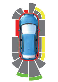
    The system provides object distance indication through the information and entertainment display.

    As the distance to the object decreases, the indicator waves and the lines move toward the vehicle icon. If there is no object detected, the distance indicator lines are grey.

    read more

    Copyright © 2024 www.linautilus.com