Lincoln Nautilus: Front Disc Brake / Brake Caliper. Removal and Installation
Materials
| Name | Specification |
|---|---|
| Motorcraft® Metal Brake Parts Cleaner PM-4-A, PM-4-B, APM-4-C |
- |
Removal
NOTICE: Do not spill brake fluid on painted or plastic surfaces or damage to the surface may occur. If brake fluid is spilled onto a painted or plastic surface, immediately wash the surface with water.
NOTE: Removal steps in this procedure may contain installation details.
-
Remove the wheel and tire.
Refer to: Wheel and Tire (204-04A Wheels and Tires, Removal and Installation).
-
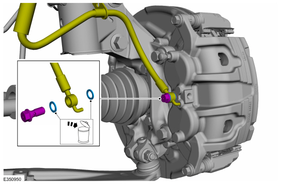
Remove the bolt and disconnect the brake hose. Discard the washers.
Torque: 18 lb.ft (25 Nm)
 |
-
NOTICE: Make sure that all openings are sealed.
Seal all the openings with clean blanking caps.
-
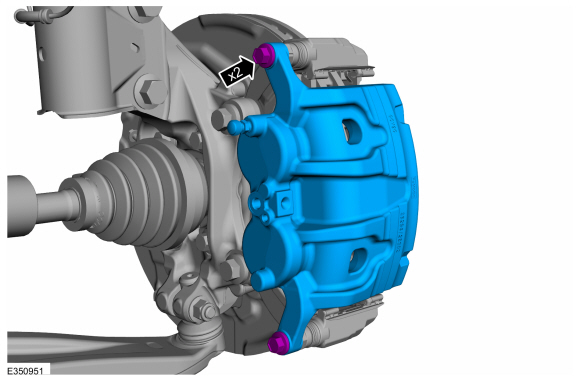
Remove the bolts and the brake caliper.
Torque: 44 lb.ft (60 Nm)
 |
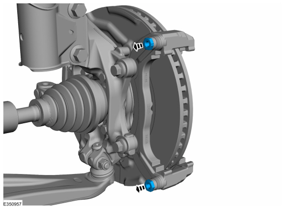
NOTE: Below steps are required when guide rods do not move freely.
-
NOTE: Note the position of the components before removal.
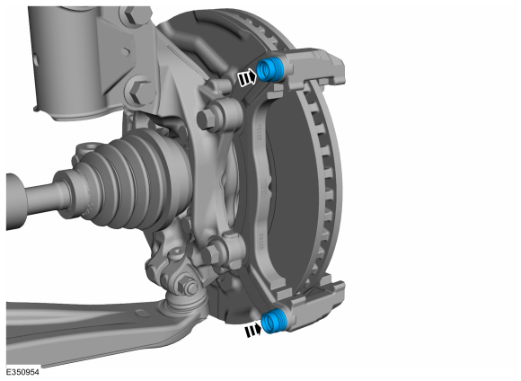
Remove the guide rods.
 |
-
Remove the guide rod boots.
 |
Installation
NOTICE: Make sure that the component is clean and free of foreign material.
NOTE: Below steps are required when guide rods do not move freely.
-
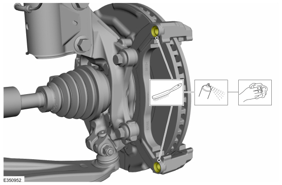
Clean the anchor plate bore using the specified material and a plastic wire brush.
Material: Motorcraft® Metal Brake Parts Cleaner / PM-4-A, PM-4-B, APM-4-C
 |
-
Install the guide rod boots into the caliper anchor plate.
 |
-
Lubricate the guide rod with grease supplied in service kit.
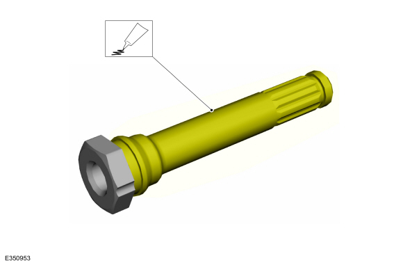 |
-
NOTE: Make sure that the components are installed to the position noted before removal.
Orient and push guide rod all the way into caliper anchor plate bore. Ensure guide rods are properly sealed into the boots.
 |
-
Rotate the guide rod to grease the complete surface.
Pull the guide rod back and forth to evenly distribute the grease.
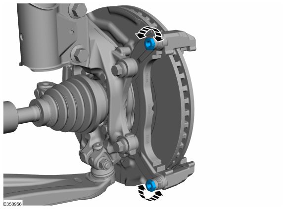 |
-
If required.
Install the new brake pads.
Refer to: Brake Pads (206-03 Front Disc Brake, Removal and Installation).
-
NOTICE: Make sure that the brake hose is not twisted when installing the brake caliper or damage to the brake flexible hose may occur.
To install, reverse the removal procedure.
-
Bleed the brake system.
Refer to: Brake System Pressure Bleeding (206-00 Brake System - General Information, General Procedures).

 Brake Caliper Anchor Plate. Removal and Installation
Removal
NOTE:
Removal steps in this procedure may contain installation details.
Remove the brake pads.
Refer to: Brake Pads (206-03 Front Disc Brake, Removal and Installation)...
Other information:
Lincoln Nautilus 2018-2026 Service Manual: Factory Mode Deactivation. General Procedures
Deactivation NOTE: During vehicle build, some modules, such as the IPC and BCM module are set in factory mode. Factory mode reduces the drain on the battery during longer periods where the vehicle is not used. While in the factory mode, various systems may be altered or disabled and the IPC displays FACTORY MODE CONTACT DEALER in the message center...
Lincoln Nautilus 2018-2026 Service Manual: Hands-Free Liftgate Actuation Upper Sensor. Removal and Installation
Removal NOTE: Removal steps in this procedure may contain installation details. Remove the rear bumper cover. Refer to: Rear Bumper Cover (501-19 Bumpers, Removal and Installation). Remove the lower rear bumper cover. Remove the rivets...
Categories
- Manuals Home
- 1st Generation Nautilus Owners Manual
- 1st Generation Nautilus Service Manual
- Folding the Exterior Mirrors - Vehicles With: Manual Folding Mirrors. Folding the Exterior Mirrors - Vehicles With: Power Folding Mirrors
- Opening the Liftgate
- Opening and Closing the Hood
- New on site
- Most important about car
USB Ports
Locating the USB Ports
Data Transfer USB Ports

The USB Ports could be in the following locations:
On the lower instrument panel. Inside the media bin. Inside the center console.Note: These USB ports can also charge devices.