Lincoln Nautilus: Rear Disc Brake / Brake Disc. Removal and Installation
Materials
| Name | Specification |
|---|---|
| Motorcraft® Metal Brake Parts Cleaner PM-4-A, PM-4-B, APM-4-C |
- |
Removal
NOTE: Removal steps in this procedure may contain installation instructions.
-
Activate the EPB service mode. WARNING:
Service actions on vehicles equipped with electronic
parking brakes may cause unexpected parking brake application, which
could result in injury to hands or fingers. Deactivate the electronic
parking brake system prior to servicing or removing rear brake
components. Failure to follow this instruction may result in serious
personal injury.
WARNING:
Service actions on vehicles equipped with electronic
parking brakes may cause unexpected parking brake application, which
could result in injury to hands or fingers. Deactivate the electronic
parking brake system prior to servicing or removing rear brake
components. Failure to follow this instruction may result in serious
personal injury.
Refer to: Electronic Parking Brake (EPB) Service Mode Activation and Deactivation (206-05 Parking Brake and Actuation, General Procedures).
-
Remove the wheel and tire.
Refer to: Wheel and Tire (204-04A Wheels and Tires, Removal and Installation).
-
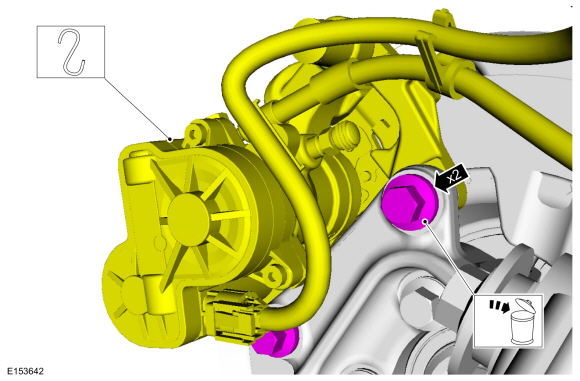
Remove the bolts and position the brake caliper and anchor plate assembly aside. Discard the bolts.
Torque: 76 lb.ft (103 Nm)
 |
-
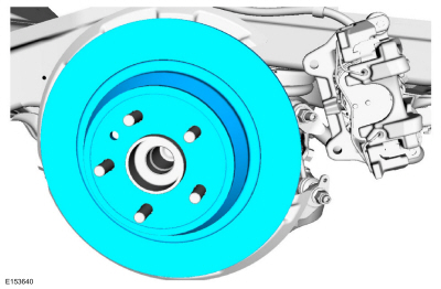
Remove the brake disc.
 |
-
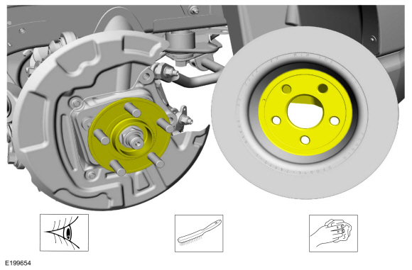
NOTICE: Make sure that the mating faces are clean and free of foreign material.
Clean the brake disc-to-wheel hub mating surfaces.
Material: Motorcraft® Metal Brake Parts Cleaner / PM-4-A, PM-4-B, APM-4-C
 |
Installation
-
NOTICE: Make sure that the brake hose is not twisted when installing the brake caliper or damage to the brake flexible hose may occur.
To install, reverse the removal procedure.
-
Deactivate the EPB service mode.
Refer to: Electronic Parking Brake (EPB) Service Mode Activation and Deactivation (206-05 Parking Brake and Actuation, General Procedures).
-
Apply the brake pedal several times to verify correct brake system operation.
 Brake Caliper Anchor Plate. Removal and Installation
Removal
NOTE:
Steps in the removal procedure may contain installation details.
Remove the brake pads.
Refer to: Brake Pads (206-04 Rear Disc Brake, Removal and Installation)...
 Brake Disc Shield. Removal and Installation
Removal
NOTE:
Removal steps in this procedure may contain installation details.
Remove the brake disc.
Refer to: Brake Disc (206-04 Rear Disc Brake, Removal and Installation)...
Other information:
Lincoln Nautilus 2018-2026 Owners Manual: Stopping the Engine
Stopping the Engine When Your Vehicle is Stationary Shift into park (P). Apply the parking brake. Wait until the engine reaches idle speed. Press the push button ignition switch. Stopping the Engine When Your Vehicle is Moving WARNING: Switching off the engine when your vehicle is still moving results in a significant decrease in braking assistance...
Lincoln Nautilus 2018-2026 Service Manual: Loadspace Trim Panel Cargo Net Hook. Removal and Installation
Special Tool(s) / General Equipment Flat Headed Screw Driver Interior Trim Remover Removal NOTE: LH shown, RH similar. NOTE: Removal steps in this procedure may contain installation details. Open the loadspace trim panel cargo net hook...
Categories
- Manuals Home
- 1st Generation Nautilus Owners Manual
- 1st Generation Nautilus Service Manual
- Locating the Pre-Collision Assist Sensors
- Interior Lamp Function. Adjusting the Instrument Panel Lighting Brightness. Ambient Lighting. Interior Lighting – Troubleshooting
- Switching the Lane Keeping System On and Off. Switching the Lane Keeping System Mode
- New on site
- Most important about car
USB Ports
Locating the USB Ports
Data Transfer USB Ports

The USB Ports could be in the following locations:
On the lower instrument panel. Inside the media bin. Inside the center console.Note: These USB ports can also charge devices.