Lincoln Nautilus: Front Disc Brake / Brake Pads. Removal and Installation
Special Tool(s) / General Equipment
| Brake Caliper Piston Retractor |
Materials
| Name | Specification |
|---|---|
| Motorcraft® Metal Brake Parts Cleaner PM-4-A, PM-4-B, APM-4-C |
- |
Removal
NOTE: Removal steps in this procedure may contain installation details.
All vehicles
-
Remove the wheel and tire.
Refer to: Wheel and Tire (204-04A Wheels and Tires, Removal and Installation).
All vehicles
-
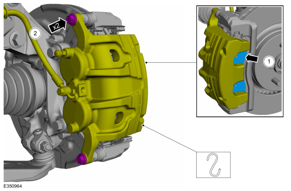
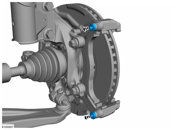
NOTICE: Make sure that no load is placed on the brake hose.
NOTICE: Do not pry in the caliper sight hole to retract the pistons as this can damage the pistons and boots.
-
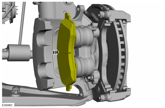
Separate the outer pad adhesive backing from housing.
-
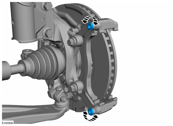
Remove the brake caliper guide pin bolts and position aside the brake caliper.
Torque: 44 lb.ft (60 Nm)
-
Separate the outer pad adhesive backing from housing.
 |
Vehicles without adhesive on brake pad insulator
-
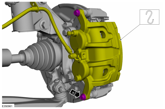
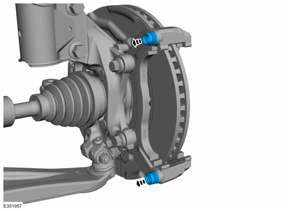
NOTICE: Make sure that no load is placed on the brake hose.
NOTICE: Do not pry in the caliper sight hole to retract the pistons as this can damage the pistons and boots.
Remove the brake caliper guide pin bolts and position aside the brake caliper.
Torque: 44 lb.ft (60 Nm)
 |
All vehicles
-
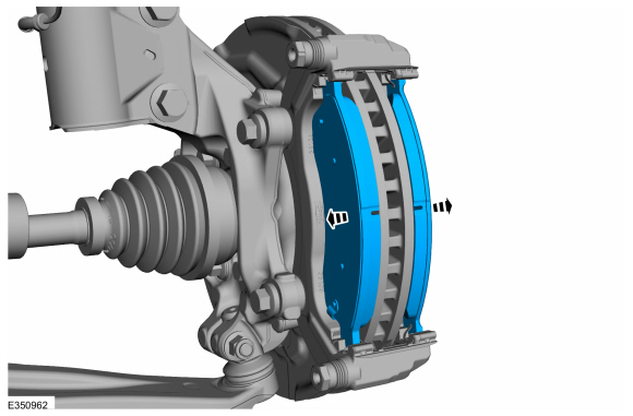
NOTICE: Brake pads with adhesive on the insulator are one-time use only. When the brake pads are separated from the brake caliper, new brake pads must be installed to prevent brake noise and shudder.
NOTICE: When installing the new brake pads make sure to remove the foil backing from the outboard brake pads. Once the foil backing is removed from the brake pads do not touch the adhesive on the backing.
NOTE: Inner and outer brake pads are not interchangeable.
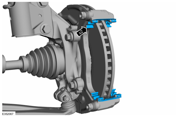
NOTE: Take extra care not to bend the retraction arms of the pad clips while inserting the brake pads.
Remove the brake pads.
 |
-
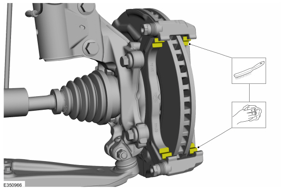
Remove and discard the brake pad clips.
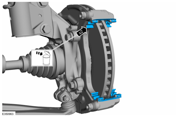 |
-
NOTICE: Protect the caliper pistons and boots when pushing the caliper piston into the caliper piston bores or damage to components may occur.
Compress the brake caliper pistons until the pistons bottoms out in the brake caliper bore.
Use the General Equipment: Brake Caliper Piston Retractor
 |
NOTE: Below steps are required when guide rods do not move freely.
-
NOTE: Note the position of the components before removal.
Remove the guide rods.
 |
-
Remove the guide rod boots.
 |
Installation
All vehicles
-
Clean the brake pad to anchor plate contact surface.
 |
-
Install the new brake pad clips.
 |
Vehicles with adhesive on brake pad insulator
NOTICE: Brake pads with adhesive on the insulator are one-time use only. When the brake pads are separated from the brake caliper, new brake pads must be installed to prevent brake noise and shudder.
NOTICE: When installing the new brake pads make sure to remove the foil backing from the outboard brake pads. Once the foil backing is removed from the brake pads do not touch the adhesive on the backing.
NOTE: A new brake caliper piston will have a protective cover. Make sure to remove the cover before installing the brake caliper.
-
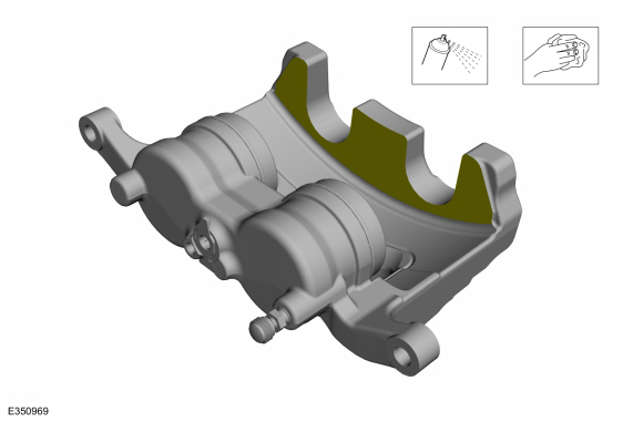
Clean all residual pad adhesive from the finger area
of the brake caliper. Make sure the finger area is free of grease and
foreign material.
Material: Motorcraft® Metal Brake Parts Cleaner / PM-4-A, PM-4-B, APM-4-C
 |
All vehicles
NOTICE: Make sure that the component is clean and free of foreign material.
NOTE: Below steps are required when guide rods do not move freely.
-
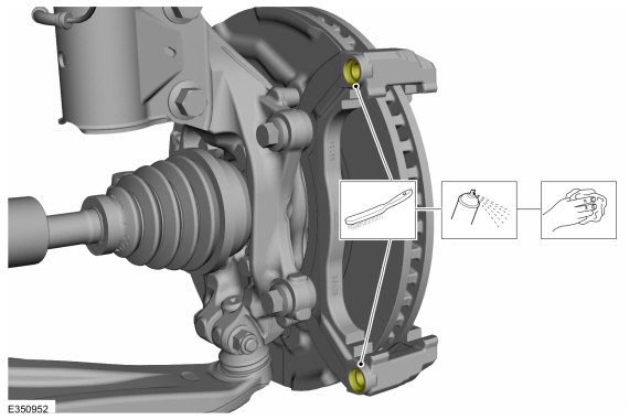
Clean the anchor plate bore using the specified material and a plastic wire brush.
Material: Motorcraft® Metal Brake Parts Cleaner / PM-4-A, PM-4-B, APM-4-C
 |
-
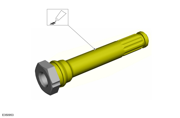
Lubricate the guide rod with grease supplied in service kit.
 |
-
NOTE: Make sure that the components are installed to the position noted before removal.
Orient and push guide rod all the way into caliper anchor plate bore.
 |
-
Rotate the guide rod to grease the complete surface.
Pull the guide rod back and forth to evenly distribute the grease.
 |
-
To install, reverse the removal procedure.
-
Apply the brake pedal several times to verify correct brake system operation.
Vehicles with adhesive on brake pad insulator
-
Start the engine and apply the brake pedal firmly 5
times to assure the outboard brake pads are bonded to the caliper.
 Brake Disc Shield. Removal and Installation
Removal
NOTE:
Removal steps in this procedure may contain installation details.
Remove the brake disc.
Refer to: Brake Disc (206-03 Front Disc Brake, Removal and Installation)...
 Front Brake Flexible Hose. Removal and Installation
Removal
NOTICE:
If the fluid is spilled on the paintwork, the affected area must be immediately washed down with cold water.
NOTE:
Removal steps in this procedure may contain installation details...
Other information:
Lincoln Nautilus 2018-2026 Service Manual: Alternating Current (AC) Power Outlet Socket. Removal and Installation
Removal WARNING: Disconnect the 12 volt battery before servicing the direct current to alternating current (DC-AC) inverter or alternating current (AC) powerpoint to prevent the risk of high voltage shock. Failure to follow this instruction may result in serious personal injury...
Lincoln Nautilus 2018-2026 Service Manual: Direct Current/Direct Current (DC/DC) Converter Control Module - Overview. Description and Operation
OVERVIEW The Low voltage Direct Current/Direct Current (DC/DC) converter, also known as the Voltage Quality Module (VQM), is on vehicles equipped with the auto-start-stop system. Auto-start-stop technology provides fuel savings by turning the engine off when the vehicle is stopped and then automatically restarting the engine when the driver is ready to continue driving...
Categories
- Manuals Home
- 1st Generation Nautilus Owners Manual
- 1st Generation Nautilus Service Manual
- Massage Seats
- Locating the Pre-Collision Assist Sensors
- Programming the Garage Door Opener to Your Garage Door Opener Motor
- New on site
- Most important about car
Traction Control
How Does Traction Control Work
If your vehicle begins to slide, the system applies the brakes to individual wheels and, when needed, reduces power at the same time. If the wheels spin when accelerating on slippery or loose surfaces, the system reduces power in order to increase traction.
Switching Traction Control On and Off
WARNING: The stability and traction control light illuminates steadily if the system detects a failure. Make sure you did not manually disable the traction control system using the information display controls or the switch. If the stability control and traction control light is still illuminating steadily, have the system serviced by an authorized dealer immediately. Operating your vehicle with the traction co