Lincoln Nautilus: Brake System - General Information / Component Bleeding. General Procedures
Lincoln Nautilus 2018-2026 Service Manual / Chassis / Brake System / Brake System - General Information / Component Bleeding. General Procedures
Special Tool(s) / General Equipment
| Master Cylinder Bleeding Set |
Bleeding
NOTICE: If the fluid is spilled on the paintwork, the affected area must be immediately washed down with cold water.
Master Cylinder
NOTE: When a new brake master cylinder has been installed, it should be primed to prevent air from entering the system.
-
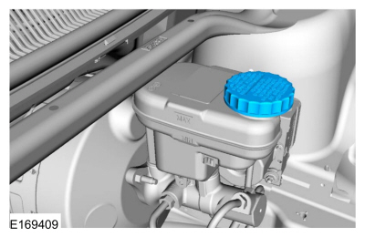
NOTE: Make sure the area around the master cylinder cap is clean and free of foreign material.
Remove the brake fluid reservoir cap.
 |
-
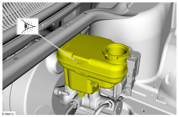
Fill the reservoir with clean, specified brake fluid.
Refer to: Specifications (206-00 Brake System - General Information, Specifications).
 |
-
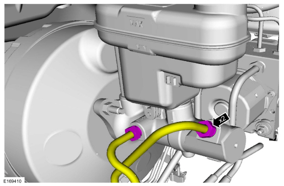
Loosen and remove the brake tube fittings.
 |
-
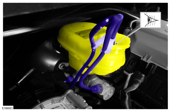
Install the master cylinder bleeding set.
Use the General Equipment: Master Cylinder Bleeding Set
 |
-
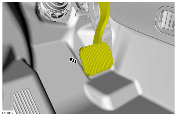
Have an assistant pump the brake pedal slowly until clear bubble free fluid flows from the brake tubes.
 |
-
Remove the master cylinder bleeding set.
Remove the General Equipment: Master Cylinder Bleeding Set
|
-
Tighten the brake tube fittings.
Refer to: Specifications (206-00 Brake System - General Information, Specifications).
|
-
Fill the reservoir with clean, specified brake fluid.
Refer to: Specifications (206-00 Brake System - General Information, Specifications).
|
-
Refer to: Brake System Pressure Bleeding (206-00 Brake System - General Information, General Procedures).
Brake Caliper, Wheel Cylinder, Brake Hose or Brake Tube
-
NOTE: Pressure bleeding the brake system is required anytime a hydraulic brake system component has been disconnected.
Refer to: Brake System Pressure Bleeding (206-00 Brake System - General Information, General Procedures).
 Brake System Pressure Bleeding. General Procedures
Special Tool(s) /
General Equipment
Brake/Clutch System Pressure Bleeder/Filler
Fluid Container
Bleeding
All vehicles
NOTICE:
If the fluid is spilled on the paintwork, the affected area must be immediately washed down with cold water...

Other information:
Lincoln Nautilus 2018-2026 Service Manual: Adaptive Front Lighting Module. Removal and Installation
Removal Remove the headlamp assembly. Refer to: Headlamp Assembly (417-01 Exterior Lighting, Removal and Installation). Remove the screws and position the adaptive front lighting module to access the connectors. Disconnect the electrical connectors and remove the adaptive front lighting module. Installation To i..
Lincoln Nautilus 2018-2026 Service Manual: Roof Panel. Removal and Installation
Special Tool(s) / General Equipment Resistance Spotwelding Equipment Scraper for Straight Edges Spherical Cutter Hot Air Gun Spot Weld Drill Bit Locking Pliers Materials Name Specification Metal Bonding AdhesiveTA-1, TA-1-B, 3M™ 08115, LORD Fusor® 108B, Henkel Teroson EP 5055 - Seam SealerTA-2-B, 3M™ 08308, LORD Fusor® 803DTM - ..
Categories
- Manuals Home
- 1st Generation Nautilus Owners Manual
- 1st Generation Nautilus Service Manual
- Replacing the Rear Wiper Blades
- Programming the Garage Door Opener to Your Garage Door Opener Motor
- Normal Scheduled Maintenance
- New on site
- Most important about car
Parking Aid Indicators. Parking Aids – Troubleshooting
Parking Aid Indicators
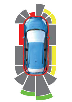
The system provides object distance indication through the information and entertainment display.
As the distance to the object decreases, the indicator waves and the lines move toward the vehicle icon. If there is no object detected, the distance indicator lines are grey.Copyright © 2026 www.linautilus.com