Lincoln Nautilus: Engine System - General Information / Connecting Rod Bearing Journal Clearance. General Procedures
Lincoln Nautilus 2018-2026 Service Manual / Powertrain / Engine / Engine System - General Information / Connecting Rod Bearing Journal Clearance. General Procedures
Check
NOTE: Refer to the appropriate Section 303-01 for the specification.
-
NOTE: The crankshaft connecting rod journals must be within specifications to check the connecting rod bearing journal clearance.
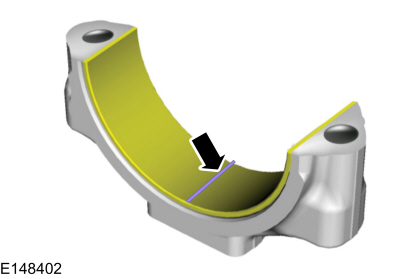
Remove the connecting rod bearing cap and connecting rod bearing.
-
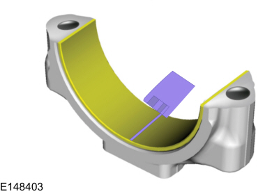
Position a piece of Plastigage across the bearing surface.
 |
-
NOTE: Do not turn the crankshaft during this step.
Install and tighten to specifications, then remove the connecting rod bearing cap.
-
Measure the Plastigage to get the connecting rod bearing
journal clearance. The Plastigage should be smooth and flat. A changing
width indicates a tapered or damaged connecting rod or connecting rod
bearing.
 |
 Compression and Cylinder Leakage Test - Gasoline. General Procedures
Make sure the oil in the crankcase is of the correct
viscosity and at the correct level and that the battery is correctly
charged. Operate the vehicle until the engine is at normal operating
temperature...
 Crankshaft End Play. General Procedures
General Equipment
Dial indicator
Dial indicator fixture
NOTE:
Refer to the appropriate Section 303-01 for the specification.
Position the crankshaft to the rear of the cylinder block...
Other information:
Lincoln Nautilus 2018-2026 Service Manual: Headlamp Leveling Module. Removal and Installation
Removal NOTE: Removal steps in this procedure may contain installation details. NOTE: If installing a new module, it is necessary to upload the module configuration information to the scan tool prior to removing the module. This information must be downloaded into the new module after installation...
Lincoln Nautilus 2018-2026 Service Manual: Rear Door Tweeter Speaker. Removal and Installation
Removal All vehicles Remove the rear door trim panel. Refer to: Rear Door Trim Panel (501-05 Interior Trim and Ornamentation, Removal and Installation). Vehicles with: Harman Revel Audio System Remove the screws and the tweeter speaker through the front of the door panel...
Categories
- Manuals Home
- 1st Generation Nautilus Owners Manual
- 1st Generation Nautilus Service Manual
- Interior Lamp Function. Adjusting the Instrument Panel Lighting Brightness. Ambient Lighting. Interior Lighting – Troubleshooting
- Auto Hold
- Opening and Closing the Hood
- New on site
- Most important about car
Clearing the Garage Door Opener. Reprogramming the Garage Door Opener. Garage Door Opener Radio Frequencies
Clearing the Garage Door Opener
Copyright © 2026 www.linautilus.com