Lincoln Nautilus Manuals

Lincoln Nautilus: Exterior Lighting / Fog Lamps. Diagnosis and Testing

DTC Charts

DTC Chart: BCM

Diagnostics in this manual assume a certain skill level and knowledge of Ford-specific diagnostic practices.
REFER to: Diagnostic Methods (100-00 General Information, Description and Operation).

  DTC Description Action
B1046:11 Front Fog Lamp Control Switch: Circuit Short To Ground   GO to Pinpoint Test D
B1047:11 Rear Fog Lamp Control Switch: Circuit Short To Ground   GO to Pinpoint Test E
B1A79:11 Rear Fog Lamp: Circuit Short To Ground   GO to Pinpoint Test B
B1A79:15 Rear Fog Lamp: Circuit Short To Battery or Open
  • If the fog lamp is inoperative, GO to Pinpoint Test B
  • If the fog lamp is always on, GO to Pinpoint Test E
U1000:00 Solid State Driver Protection Active -Driver Disabled: No Sub Type Information The module has temporarily disabled an output because an excessive current draw exists (such as a short to ground). The BCM cannot enable the output until the cause of the short is corrected. ADDRESS all other Diagnostic Trouble Codes (DTCs) first. After the cause of the concern is corrected, CLEAR the Diagnostic Trouble Codes (DTCs). REPEAT the self-test. For additional information on BCM Field Effect Transistor (FET) protection,
REFER to: Module Controlled Functions - System Operation and Component Description (419-10 Multifunction Electronic Modules, Description and Operation).
U3000:49 Control Module: Internal Electronic Failure The module has permanently disabled an output because an excessive current draw fault (such as a short to ground) has exceeded the limits that the BCM can withstand. The cause of the excessive current draw MUST be corrected before a new BCM is installed. ADDRESS all other Diagnostic Trouble Codes (DTCs) first. After the cause of the concern is corrected, INSTALL a new BCM. Refer to the appropriate Removal and Installation procedure in Section 419-10. For additional information on BCM Field Effect Transistor (FET) protection,
REFER to: Module Controlled Functions - System Operation and Component Description (419-10 Multifunction Electronic Modules, Description and Operation).
All other BCM Diagnostic Trouble Codes (DTCs) -  
REFER to: Body Control Module (BCM) (419-10 Multifunction Electronic Modules) .

Symptom Chart

Symptom Chart: Fog Lamps

Diagnostics in this manual assume a certain skill level and knowledge of Ford-specific diagnostic practices.
REFER to: Diagnostic Methods (100-00 General Information, Description and Operation).

Condition Possible Sources Actions
A module does not respond to the diagnostic scan tool
  • Fuse
  • Wiring, terminals or connectors
  • Module
 
REFER to: Communications Network (418-00 Module Communications Network) .
Both front fog lamps are inoperative Refer to the Pinpoint Test   GO to Pinpoint Test A
The rear fog lamp is inoperative Refer to the Pinpoint Test   GO to Pinpoint Test B
An individual front fog lamp is inoperative or always on Refer to the Pinpoint Test   GO to Pinpoint Test C
The front fog lamps are on continuously Refer to the Pinpoint Test   GO to Pinpoint Test D
The rear fog lamp is on continuously Refer to the Pinpoint Test   GO to Pinpoint Test E

Pinpoint Tests


PINPOINT TEST A: BOTH FRONT FOG LAMPS ARE INOPERATIVE

Refer to Wiring Diagrams Cell 86 for schematic and connector information.

Normal Operation and Fault Conditions

REFER to: Exterior Lighting - Overview (417-01 Exterior Lighting, Description and Operation).
REFER to: Exterior Lighting (417-01 Exterior Lighting) .

Possible Sources

  • Wiring, terminals or connectors
  • Headlamp switch
  • Headlamps concern
  • BCM

Visual Inspection and Pre-checks

  • Inspect the headlamp switch for damage.
A1 CHECK THE LOW BEAM OPERATION
  • Ignition ON.
  • Place the headlamp switch in the HEADLAMPS then the OFF position.

Do the low beams operate correctly?
Yes GO to A2
No
REFER to: Headlamps (417-01 Exterior Lighting, Diagnosis and Testing).

A2 CHECK THE HEADLAMP SWITCH
  • Using a diagnostic scan tool, perform the BCM self-test.

Are any headlamp switch module BCM Diagnostic Trouble Codes (DTCs) present?
Yes
REFER to: Headlamps (417-01 Exterior Lighting, Diagnosis and Testing).
No INSTALL a new headlamp switch.
REFER to: Headlamp Switch (417-01 Exterior Lighting, Removal and Installation).
TEST the system for normal operation. If the condition returns, GO to A3

A3 CHECK FOR CORRECT BCM (BODY CONTROL MODULE) OPERATION
  • Disconnect and inspect all BCM connectors.
  • Repair:
    • corrosion (install new connector or terminals – clean module pins)
    • damaged or bent pins – install new terminals/pins
    • pushed-out pins – install new pins as necessary
  • Reconnect the BCM connectors. Make sure they seat and latch correctly.
  • Operate the system and determine if the concern is still present.

Is the concern still present?
Yes CHECK OASIS for any applicable service articles: TSB , GSB , SSM or FSA . If a service article exists for this concern, DISCONTINUE this test and FOLLOW the service article instructions. If no service articles address this concern, INSTALL a new BCM. Refer to the appropriate Removal and Installation procedure in Section 419-10. .
No The system is operating correctly at this time. The concern may have been caused by module connections. ADDRESS the root cause of any connector or pin issues.

PINPOINT TEST B: THE REAR FOG LAMP IS INOPERATIVE

Refer to Wiring Diagrams Cell 86 for schematic and connector information.

Normal Operation and Fault Conditions

REFER to: Exterior Lighting - Overview (417-01 Exterior Lighting, Description and Operation).
REFER to: Exterior Lighting (417-01 Exterior Lighting) .

DTC Fault Trigger Conditions

DTC Description Fault Trigger Condition
BCM B1A79:11 Rear Fog Lamp: Circuit Short To Ground A continuous memory and on-demand DTC that sets when the BCM detects a short to ground from the rear fog lamp output circuit.
BCM B1A79:15 Rear Fog Lamp: Circuit Short To Battery Or Open A continuous memory and on-demand DTC that sets when the BCM detects an open or short to voltage from the rear fog lamp output circuit.
BCM U1000:00 Solid State Driver Protection Active -Driver Disabled: No Sub Type Information This DTC sets when the BCM has temporarily shut down the output driver. The module has temporarily disabled an output because an excessive current draw exists (such as a short to ground). The BCM cannot enable the output until the cause of the short is corrected, the Diagnostic Trouble Codes (DTCs) have been cleared and a successful self-test is run. For additional information on BCM Field Effect Transistor (FET) protection,
REFER to: Module Controlled Functions - System Operation and Component Description (419-10 Multifunction Electronic Modules, Description and Operation).
BCM U3000:49 Control Module: Internal Electronic Failure This DTC sets when the BCM has permanently shut down the output driver. The module has permanently disabled an output because an excessive current draw fault (such as a short to ground) has exceeded the limits that the BCM can withstand. CORRECT the cause of the excessive current draw before installing a new BCM . For additional information on BCM Field Effect Transistor (FET) protection,
REFER to: Module Controlled Functions - System Operation and Component Description (419-10 Multifunction Electronic Modules, Description and Operation).

Possible Sources

  • Bulb
  • Wiring, terminals or connectors
  • Headlamp switch
  • BCM

Visual Inspection and Pre-checks

  • Inspect the fog lamp bulb and make sure it is OK.
  • Inspect the headlamp switch for damage.
B1 CHECK THE HEADLAMP SWITCH
  • Ignition ON.
  • Using a diagnostic scan tool, perform the BCM self-test.

Are any headlamp switch module BCM Diagnostic Trouble Codes (DTCs) present?
Yes
REFER to: Headlamps (417-01 Exterior Lighting, Diagnosis and Testing).
No INSTALL a new headlamp switch.
REFER to: Headlamp Switch (417-01 Exterior Lighting, Removal and Installation).
TEST the system for normal operation. If the condition returns, GO to B2

B2 CHECK FOR VOLTAGE TO THE REAR FOG LAMP
  • Connect: Headlamp Switch C205.
  • Connect: BCM C2280F.
  • Disconnect: Rear Fog Lamp C436.
  • Ignition ON.
  • Place the headlamp switch in the PARKING LAMPS position and engage the rear fog lamp switch.
  • Measure:
    Click to display connectors
    Positive Lead Measurement / Action Negative Lead
      C436-1   Ground

Is the voltage greater than 11 volts?
Yes GO to B4
No GO to B3

B3 REPEAT THE ON-DEMAND SELF-TEST AND CHECK FOR VOLTAGE TO THE REAR FOG LAMP
  • Using a diagnostic scan tool, perform the BCM self-test.
  • Clear the Diagnostic Trouble Codes (DTCs) and repeat the self-test (required to enable the lamp output driver if DTC U1000:00 is present).
  • Measure:
    Click to display connectors
    Positive Lead Measurement / Action Negative Lead
      C436-1   Ground

Is the voltage greater than 11 volts?
Yes INSTALL a new rear fog lamp.
No GO to B5

B4 CHECK FOG LAMP GROUND CIRCUIT FOR AN OPEN
  • Measure:
    Click to display connectors
    Positive Lead Measurement / Action Negative Lead
      C436-1   C436-2

Is the voltage greater than 11 volts?
Yes INSTALL a new rear fog lamp.
No REPAIR the circuit.

B5 CHECK FOG LAMP VOLTAGE SUPPLY CIRCUIT FOR A SHORT TO GROUND
  • Place the headlamp switch in the OFF position.
  • Ignition OFF.
  • Disconnect: BCM C2280F.
  • Measure:
    Click to display connectors
    Positive Lead Measurement / Action Negative Lead
      C436-1   Ground

Is the resistance greater than 10,000 ohms?
Yes GO to B6
No REPAIR the circuit. After the repair:
If no Diagnostic Trouble Codes (DTCs) are present, TEST the system for normal operation.
If DTC U1000:00 is present, CLEAR the Diagnostic Trouble Codes (DTCs) and REPEAT the self-test (required to enable the lamp output driver if DTC U1000:00 is present).
If DTC U3000:49 is present, INSTALL a new BCM. Refer to the appropriate Removal and Installation procedure in Section 419-10.

B6 CHECK FOG LAMP VOLTAGE SUPPLY CIRCUIT FOR AN OPEN
  • Measure:
    Click to display connectors
    Positive Lead Measurement / Action Negative Lead
      C436-1   C2280F-25

Is the resistance less than 3 ohms?
Yes GO to B7
No REPAIR the circuit.

B7 CHECK FOR CORRECT BCM (BODY CONTROL MODULE) OPERATION
  • Disconnect and inspect all BCM connectors.
  • Repair:
    • corrosion (install new connector or terminals – clean module pins)
    • damaged or bent pins – install new terminals/pins
    • pushed-out pins – install new pins as necessary
  • Reconnect the BCM connectors. Make sure they seat and latch correctly.
  • Operate the system and determine if the concern is still present.

Is the concern still present?
Yes CHECK OASIS for any applicable service articles: TSB , GSB , SSM or FSA . If a service article exists for this concern, DISCONTINUE this test and FOLLOW the service article instructions. If no service articles address this concern, INSTALL a new BCM. Refer to the appropriate Removal and Installation procedure in Section 419-10. .
No The system is operating correctly at this time. The concern may have been caused by module connections. ADDRESS the root cause of any connector or pin issues.

PINPOINT TEST C: AN INDIVIDUAL FRONT FOG LAMP IS INOPERATIVE OR ALWAYS ON

Refer to Wiring Diagrams Cell 86 for schematic and connector information.

Normal Operation and Fault Conditions

REFER to: Exterior Lighting - Overview (417-01 Exterior Lighting, Description and Operation).
REFER to: Exterior Lighting (417-01 Exterior Lighting) .

Possible Sources

  • Wiring, terminals or connectors
  • Front fog lamp assembly
  • BCM

Visual Inspection and Pre-checks

  • Inspect the front fog lamp for damage.
C1 CHECK THE LOW BEAM OPERATION
  • Ignition ON.
  • Place the headlamp switch in the PARKING LAMPS position then the OFF position.

Do the parking lamps operate correctly?
Yes GO to C2
No
REFER to: Parking, Rear and License Plate Lamps (417-01 Exterior Lighting, Diagnosis and Testing).

C2 CHECK FRONT FOG LAMP CIRCUITS FOR A SHORT TO VOLTAGE
  • Ignition OFF.
  • Disconnect: LH Front Fog Lamp C152 or RH Front Fog Lamp C162.
  • Disconnect: LH Headlamp C1021A or RH Headlamp C1041A.
  • Ignition ON.
  • Measure:
    Click to display connectors

      LH Front Fog Lamp


    Positive Lead Measurement / Action Negative Lead
      C152-1   Ground
      C152-2   Ground
      C152-3   Ground
      C152-4   Ground
      C152-5   Ground
      C152-6   Ground

    Click to display connectors

      RH Front Fog Lamp


    Positive Lead Measurement / Action Negative Lead
      C162-1   Ground
      C162-2   Ground
      C162-3   Ground
      C162-4   Ground
      C162-5   Ground
      C162-6   Ground

Is any voltage present?
Yes REPAIR the circuit in question.
No GO to C3

C3 CHECK THE FRONT FOG LAMP CIRCUITS FOR A SHORT TO GROUND
  • Ignition OFF.
  • Measure:
    Click to display connectors

      LH Front Fog Lamp


    Positive Lead Measurement / Action Negative Lead
      C152-1   Ground
      C152-2   Ground
      C152-3   Ground
      C152-4   Ground
      C152-5   Ground
      C152-6   Ground

    Click to display connectors

      RH Front Fog Lamp


    Positive Lead Measurement / Action Negative Lead
      C162-1   Ground
      C162-2   Ground
      C162-3   Ground
      C162-4   Ground
      C162-5   Ground
      C162-6   Ground

Is the resistance greater than 10,000 ohms?
Yes GO to C4
No REPAIR the circuit in question.

C4 CHECK THE FRONT FOG LAMP CIRCUITS FOR A SHORT TOGETHER
  • Ignition OFF.
  • Measure:
    Click to display connectors

      LH Front Fog Lamp


    Positive Lead Measurement / Action Negative Lead
      C152-1   C152-2
      C152-1   C152-3
      C152-1   C152-4
      C152-1   C152-5
      C152-1   C152-6
      C152-2   C152-3
      C152-2   C152-4
      C152-2   C152-5
      C152-2   C152-6
      C152-3   C152-4
      C152-3   C152-5
      C152-3   C152-6
      C152-4   C152-5
      C152-4   C152-6
      C152-5   C152-6

    Click to display connectors

      RH Front Fog Lamp


    Positive Lead Measurement / Action Negative Lead
      C162-1   C162-2
      C162-1   C162-3
      C162-1   C162-4
      C162-1   C162-5
      C162-1   C162-6
      C162-2   C162-3
      C162-2   C162-4
      C162-2   C162-5
      C162-2   C162-6
      C162-3   C162-4
      C162-3   C162-5
      C162-3   C162-6
      C162-4   C162-5
      C162-4   C162-6
      C162-5   C162-6

Is the resistance greater than 10,000 ohms?
Yes GO to C5
No REPAIR the circuit in question.

C5 CHECK THE FRONT FOG LAMP CIRCUITS FOR AN OPEN
  • Measure:
    Click to display connectors

      LH Front Fog Lamp


    Positive Lead Measurement / Action Negative Lead
      C152-1   C1021A-12
      C152-2   C1021A-13
      C152-3   C1021A-7
      C152-4   C1021A-4
      C152-5   C1021A-6
      C152-6   C1021A-5

    Click to display connectors

      RH Front Fog Lamp


    Positive Lead Measurement / Action Negative Lead
      C162-1   C1041A-12
      C162-2   C1041A-13
      C162-3   C1041A-7
      C162-4   C1041A-4
      C162-5   C1041A-6
      C162-6   C1041A-5

Is the resistance less than 3 ohms?
Yes GO to C6
No REPAIR the circuit.

C6 CHECK THE ADAPTIVE FRONT LIGHTING MODULE
  • Connect all disconnected connectors.
  • Substitute the known good adaptive front lighting module from the opposite headlamp.
  • Ignition ON.
  • Using a diagnostic scan tool, carry out the BCM LIN New Module Initialization.
  • Clear the Diagnostic Trouble Codes (DTCs), Repeat the self-test (required to enable the lamp output driver) and cycle the ignition OFF and ON. Test the system for normal operation.

Does the suspect front turn lamp operate correctly?
Yes REMOVE the known good adaptive front lighting module. INSTALL a new adaptive front lighting module.
REFER to: Adaptive Front Lighting Module (417-01 Exterior Lighting, Removal and Installation).
No REMOVE the known good adaptive front lighting module. INSTALL a new front fog lamp.

PINPOINT TEST D: THE FRONT FOG LAMPS ARE ON CONTINUOUSLY

Refer to Wiring Diagrams Cell 86 for schematic and connector information.

Normal Operation and Fault Conditions

REFER to: Exterior Lighting - Overview (417-01 Exterior Lighting, Description and Operation).
REFER to: Exterior Lighting (417-01 Exterior Lighting) .

DTC Fault Trigger Conditions

DTC Description Fault Trigger Condition
BCM B1046:11 Front Fog Lamp Control Switch: Circuit Short To Ground A continuous and on-demand DTC that sets when the BCM detects a short to ground on the headlamp switch input circuits.

Possible Sources

  • Wiring, terminals or connectors
  • Headlamp switch
  • BCM

Visual Inspection and Pre-checks

  • Inspect the headlamp switch for damage.
D1 CHECK THE HEADLAMP SWITCH
  • Ignition ON.
  • Using a diagnostic scan tool, perform the BCM self-test.

Are any headlamp switch module BCM Diagnostic Trouble Codes (DTCs) present?
Yes
REFER to: Headlamps (417-01 Exterior Lighting, Diagnosis and Testing).
No INSTALL a new headlamp switch.
REFER to: Headlamp Switch (417-01 Exterior Lighting, Removal and Installation).
TEST the system for normal operation. If the condition returns, GO to D2

D2 CHECK FOR CORRECT BCM (BODY CONTROL MODULE) OPERATION
  • Disconnect and inspect all BCM connectors.
  • Repair:
    • corrosion (install new connector or terminals – clean module pins)
    • damaged or bent pins – install new terminals/pins
    • pushed-out pins – install new pins as necessary
  • Reconnect the BCM connectors. Make sure they seat and latch correctly.
  • Operate the system and determine if the concern is still present.

Is the concern still present?
Yes CHECK OASIS for any applicable service articles: TSB , GSB , SSM or FSA . If a service article exists for this concern, DISCONTINUE this test and FOLLOW the service article instructions. If no service articles address this concern, INSTALL a new BCM. Refer to the appropriate Removal and Installation procedure in Section 419-10. .
No The system is operating correctly at this time. The concern may have been caused by module connections. ADDRESS the root cause of any connector or pin issues.

PINPOINT TEST E: THE REAR FOG LAMP IS ON CONTINUOUSLY

Refer to Wiring Diagrams Cell 86 for schematic and connector information.

Normal Operation and Fault Conditions

REFER to: Exterior Lighting - Overview (417-01 Exterior Lighting, Description and Operation).
REFER to: Exterior Lighting (417-01 Exterior Lighting) .

DTC Fault Trigger Conditions

DTC Description Fault Trigger Condition
BCM B1047:11 Rear Fog Lamp Control Switch: Circuit Short To Ground A continuous memory and on-demand DTC that sets when the BCM detects a short to ground on the rear fog lamp on input circuit.
BCM B1A79:15 Rear Fog Lamp: Circuit Short To Battery Or Open A continuous memory and on-demand DTC that sets when the BCM detects an open or short to voltage from the rear fog lamp output circuit.

Possible Sources

  • Wiring, terminals or connectors
  • Headlamp switch
  • BCM

Visual Inspection and Pre-checks

  • Inspect the headlamp switch for damage.
E1 CHECK THE HEADLAMP SWITCH
  • Ignition ON.
  • Using a diagnostic scan tool, perform the BCM self-test.

Are any headlamp switch module BCM Diagnostic Trouble Codes (DTCs) present?
Yes
REFER to: Headlamps (417-01 Exterior Lighting, Diagnosis and Testing).
No INSTALL a new headlamp switch.
REFER to: Headlamp Switch (417-01 Exterior Lighting, Removal and Installation).
TEST the system for normal operation. If the condition returns, GO to E2

E2 CHECK FOR CORRECT BCM (BODY CONTROL MODULE) OPERATION
  • Disconnect and inspect all BCM connectors.
  • Repair:
    • corrosion (install new connector or terminals – clean module pins)
    • damaged or bent pins – install new terminals/pins
    • pushed-out pins – install new pins as necessary
  • Reconnect the BCM connectors. Make sure they seat and latch correctly.
  • Operate the system and determine if the concern is still present.

Is the concern still present?
Yes CHECK OASIS for any applicable service articles: TSB , GSB , SSM or FSA . If a service article exists for this concern, DISCONTINUE this test and FOLLOW the service article instructions. If no service articles address this concern, INSTALL a new BCM. Refer to the appropriate Removal and Installation procedure in Section 419-10. .
No The system is operating correctly at this time. The concern may have been caused by module connections. ADDRESS the root cause of any connector or pin issues.


    Daytime Running Lamps (DRL). Diagnosis and Testing

    Symptom Charts Symptom Chart: DRL Diagnostics in this manual assume a certain skill level and knowledge of Ford-specific diagnostic practices. REFER to: Diagnostic Methods (100-00 General Information, Description and Operation)...

    Headlamps. Diagnosis and Testing

    DTC Charts DTC Chart: BCM Diagnostics in this manual assume a certain skill level and knowledge of Ford-specific diagnostic practices. REFER to: Diagnostic Methods (100-00 General Information, Description and Operation)...

    Other information:

    Lincoln Nautilus 2018-2024 Owners Manual: Personal Profiles


    How Do Personal Profiles Work This feature allows you to create multiple personal profiles enabling users to personalize vehicle’s settings such as seats and mirrors, as well as non-positional settings like radio, navigation, driver assist system settings...

    Lincoln Nautilus 2018-2024 Service Manual: Rear Parking Aid Sensor. Removal and Installation


    Removal NOTE: This procedure can be used for all locations of the component. Remove the rear bumper cover. Refer to: Rear Bumper Cover (501-19) . Remove the rear parking aid sensor. Disconnect the rear parking aid sensor electrical connector...

    Categories

    Replacing the Rear Wiper Blades

    Lincoln Nautilus. Replacing the Rear Wiper Blades

    Lift the wiper arm.

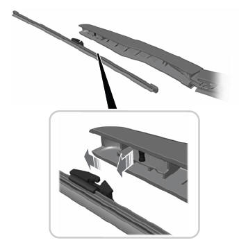
    Note: Do not hold the wiper blade to lift the wiper arm.

    Remove the wiper blade.

    read more

    Copyright © 2024 www.linautilus.com