Lincoln Nautilus: Front Seats / Front Seat Backrest Cover. Removal and Installation
Removal
NOTE: Driver seat shown, passenger seat similar.
-
Remove the side airbag.
Refer to: Side Airbag (501-20B Supplemental Restraint System, Removal and Installation).
-
Remove the head restraint guide sleeves.
Refer to: Front Head Restraint Guide Sleeve (501-10A Front Seats, Removal and Installation).
-
Disconnect the heated backrest mat electrical connector.
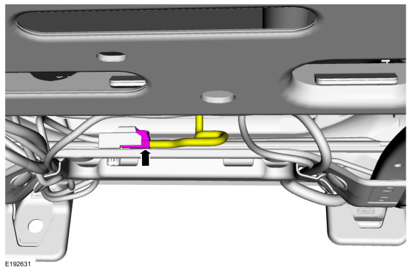 |
-
If equipped.
Remove the front seat backrest blower motor.
Refer to: Front Seat Backrest Blower Motor (501-10A Front Seats, Removal and Installation).
-
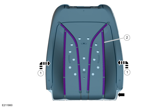
On both sides.
Release the backrest cover side J-clips.
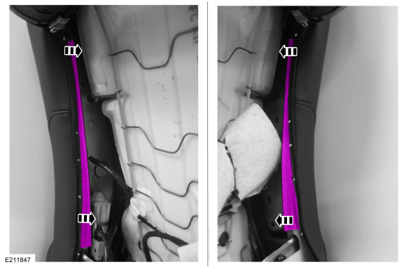 |
-
Release the backrest cover upper J-clip.
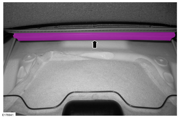 |
-
Remove the backrest cover pin-type retainers and release the cover tab.
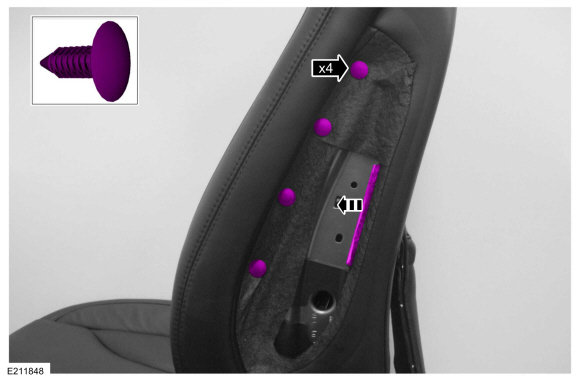 |
-
NOTICE: Use care when separating the seat backrest cover from the hook-and-loop strips or the hook-and-loop strips may be torn from the seat backrest foam.
Partially invert the lower portion of the backrest cover.
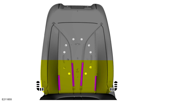 |
-
Remove the backrest cover and foam as an assembly.
.jpg) |
-
NOTICE: Use care when separating the seat backrest cover from the hook-and-loop strips or the hook-and-loop strips may be torn from the seat backrest foam.
NOTE: This step is only necessary when installing a new backrest cover.
Remove the backrest cover.
-
Invert the backrest cover.
-
Release the backrest cover hook-and-loop strips.
-
Invert the backrest cover.
 |
Installation
-
To install, reverse the removal procedure..jpg) WARNING:
Inspect the seat side airbag, airbag cavity,
mounting surface and deployment chute for damage or the presence of
foreign material. Remove all foreign material. Install a new side airbag
if it is damaged. Install a new deployment chute if the deployment
chute is damaged. Failure to follow these instructions may result in the
seat side airbag deploying incorrectly and increase the risk of serious
personal injury or death in a crash.
WARNING:
Inspect the seat side airbag, airbag cavity,
mounting surface and deployment chute for damage or the presence of
foreign material. Remove all foreign material. Install a new side airbag
if it is damaged. Install a new deployment chute if the deployment
chute is damaged. Failure to follow these instructions may result in the
seat side airbag deploying incorrectly and increase the risk of serious
personal injury or death in a crash.
 Front Seat Backrest Blower Motor. Removal and Installation
Removal
NOTE:
Driver seat shown, passenger seat similar.
Depower the SRS .
Refer to: Supplemental Restraint System (SRS) Depowering (501-20B)
...
 Front Seat Control Switch. Removal and Installation
Special Tool(s) /
General Equipment
Interior Trim Remover
Removal
NOTE:
Driver seat control switch shown, passenger seat control switch similar...
Other information:
Lincoln Nautilus 2018-2026 Service Manual: Passenger Temperature Door Actuator. Removal and Installation
Removal Refer to: Passenger Knee Airbag (501-20B Supplemental Restraint System, Removal and Installation). Remove the HCM . Remove the headlamp control module bracket bolts and the HCM . Torque: 80 lb.in (9 Nm) Disconnect the electrical connectors...
Lincoln Nautilus 2018-2026 Service Manual: D-Pillar Speaker. Removal and Installation
Removal NOTE: Removal steps in this procedure may contain installation details. Remove the D-pillar trim panel. Refer to: D-Pillar Trim Panel (501-05 Interior Trim and Ornamentation, Removal and Installation). Remove the bolts and the D-pillar speaker...
Categories
- Manuals Home
- 1st Generation Nautilus Owners Manual
- 1st Generation Nautilus Service Manual
- Fuel Quality
- Normal Scheduled Maintenance
- Auto Hold
- New on site
- Most important about car
Replacing the Rear Wiper Blades
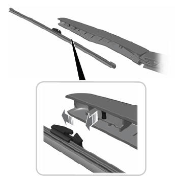
Note: Do not hold the wiper blade to lift the wiper arm.
Remove the wiper blade.