Lincoln Nautilus: Instrument Panel and Console / Instrument Panel. Removal and Installation
Special Tool(s) /
General Equipment
Removal
All vehicles
NOTE:
Removal steps in this procedure may contain installation details.
-
Recover the refrigerant.
Refer to: Air Conditioning (A/C) System Recovery,
Evacuation and Charging - Vehicles With: R1234YF Refrigerant (412-00
Climate Control System - General Information)
.
2.0L
-
Remove the air cleaner outlet pipe.
Refer to: Air Cleaner Outlet Pipe (303-12A Intake Air Distribution and
Filtering - 2.0L EcoBoost (184kW/250PS) – MI4, Removal and
Installation).
Vehicles with 2.7L engine
-
Remove the air cleaner outlet pipe RH side.
Refer to: Air Cleaner Outlet Pipe RH (303-12B Intake Air Distribution
and Filtering - 2.7L EcoBoost (238kW/324PS), Removal and Installation).
-
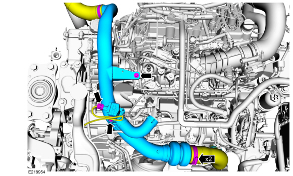
NOTICE:
The turbocharger compressor vanes can be damaged
by even the smallest particles. When removing any turbocharger or
engine air intake system component, ensure that no debris enters the
system. Failure to do so may result in damage to the turbocharger.
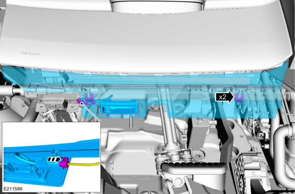
Loosen the clamps. Disconnect the electrical connector and pushpin.
Remove the bolt and the CAC intake pipe from the right side.
Torque:
Stage 1:
Clamps:
48 lb.in (5.4 Nm)
Stage 2:
Bolt:
71 lb.in (8 Nm)
All vehicles
-
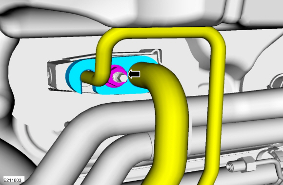
NOTE:
Make sure all openings are sealed.
Remove the evaporator pipe nut, position the flange and pipe aside.
Torque:
159 lb.in (18 Nm)
-
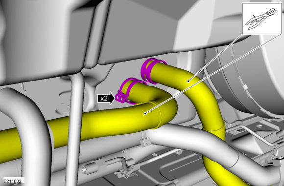
NOTE:
Make sure all openings are sealed.
Clamp and disconnect the heater hoses.
-
Remove the cowl panel grille.
Refer to: Cowl Panel Grille (501-02 Front End Body Panels, Removal and Installation).
-
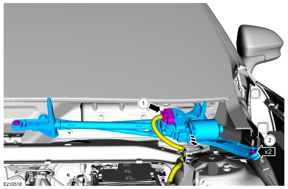
Remove the wiper linkage assembly.
-
Disconnect the electrical connector.
-
Remove the bolts.
Torque:
62 lb.in (7 Nm)
-
Remove the bolts.
Torque:
18 lb.ft (25 Nm)
-
Remove both front doors.
Refer to: Front Door (501-03 Body Closures, Removal and Installation).
-
Remove both front seats.
Refer to: Front Seat (501-10A Front Seats, Removal and Installation).
-
Remove the floor console.
Refer to: Floor Console (501-12 Instrument Panel and Console, Removal and Installation).
-
Remove the RH and LH A-pillar trim panel.
Refer to: A-Pillar Trim Panel (501-05 Interior Trim and Ornamentation, Removal and Installation).
-
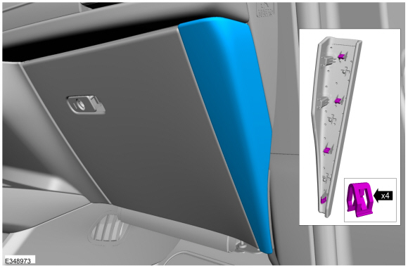
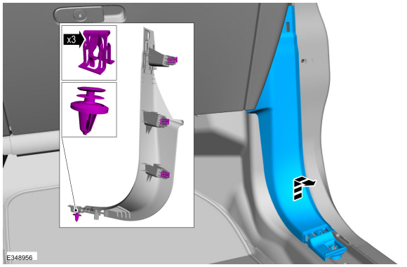
Release the clips and the remove the trim panel.
-
On boths sides, release the clips and the remove the trim panel.
-
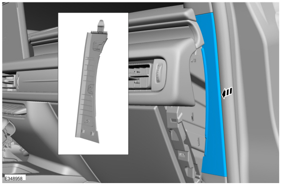
NOTE:
RH side shown LH side similar.
On both sides, remove the trim panel.
-
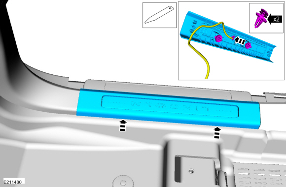
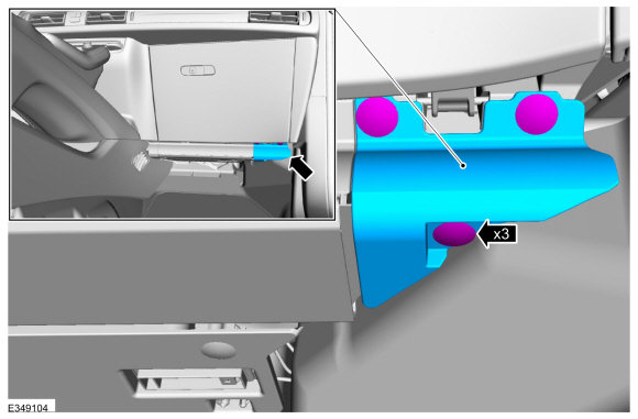
Release the clips and remove the RH sill plate.
-
Disconnect the electrical connector.
Use the General Equipment: Interior Trim Remover
-
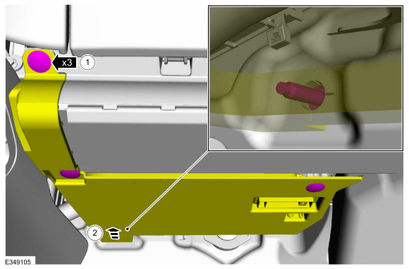
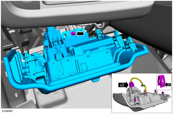
Release the clips and remove the RH lower cowl trim panel.
Use the General Equipment: Interior Trim Remover
-
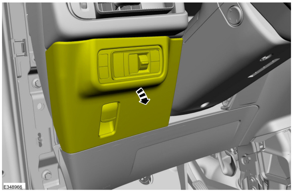
Remove the pin-type retainers and the lower RH trim panel.
-
-
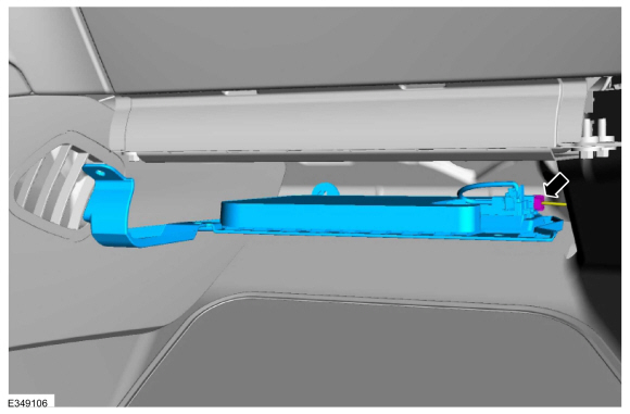
Remove the hush panel pin-type retainers.
-
Position the insulation panel away from the instrument panel.
-
Remove the insulator panel.
-
Disconnect the electrical connector.
-
Remove the push pins and position the carpet aside.
-
Release the clips and remove the LH sill plate.
-
Disconnect the electrical connector.
Use the General Equipment: Interior Trim Remover
-
Release the clips and lower the trim trim panel.
-
Remove the bolt and the trim panel.
-
Disconnect the electrical connectors.
Torque:
22 lb.in (2.5 Nm)
-
Remove the hood release handle.
Refer to: Hood Latch Release Handle (501-14 Handles, Locks, Latches and Entry Systems, Removal and Installation).
-
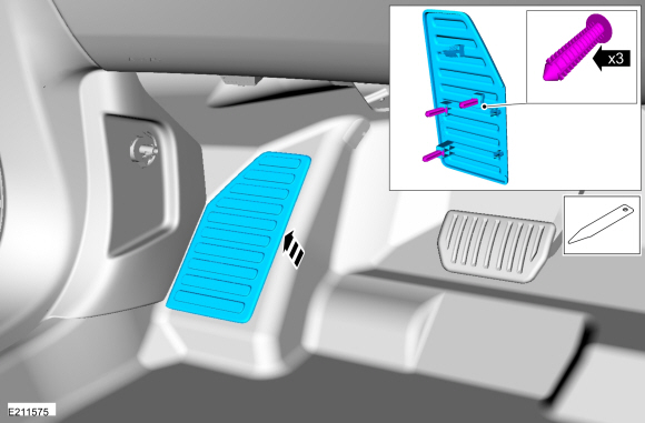
Remove the foot rest pad.
Use the General Equipment: Interior Trim Remover
-
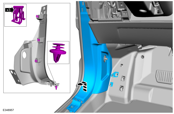
Release the clips and remove the LH lower cowl trim panel.
Use the General Equipment: Interior Trim Remover
-
Remove the retainer and position the carpet aside.
-
Disconnect the electrical connectors and detach from the lower RH cowl.
-
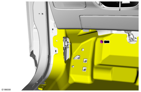
Remove the HVAC nut.
Torque:
71 lb.in (8 Nm)
-
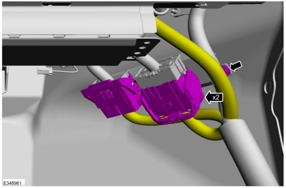
Disconnect the electrical connectors, release the harness retainers and position both harnesses aside.
-
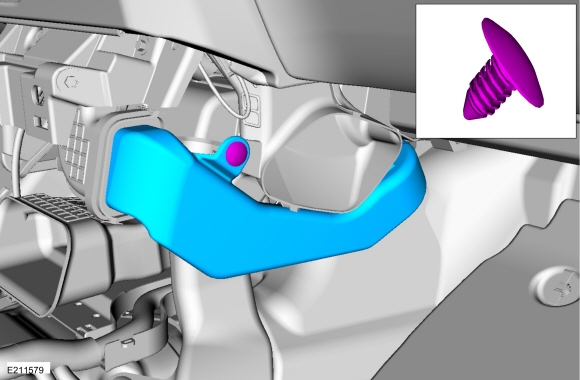
Remove the push pin and the HVAC duct.
-
Remove the push pin and the RH HVAC duct.
-
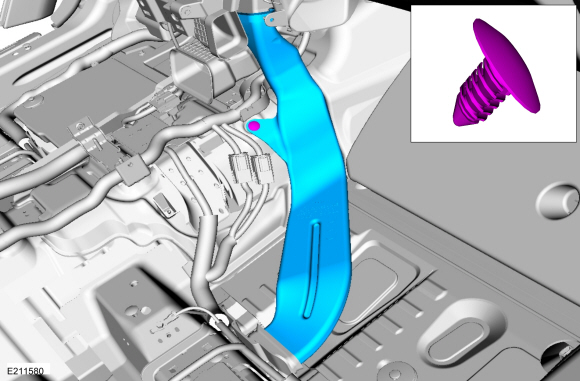
Remove the push pin and the LH HVAC duct.
-
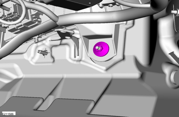
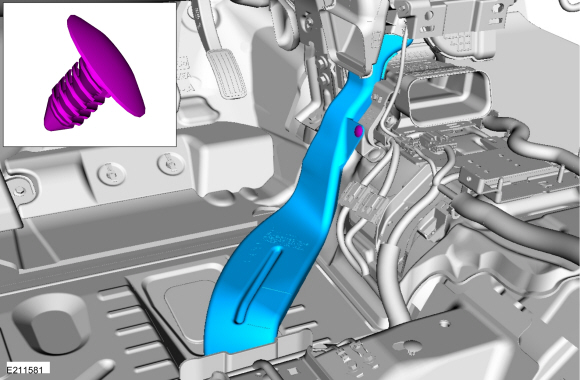
Remove the bolt, push pin and the center HVAC duct.
-
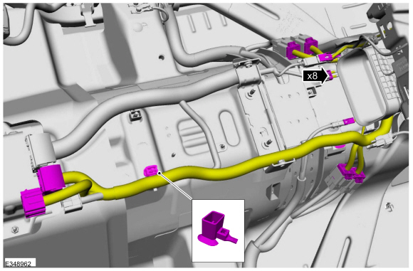
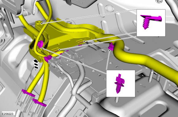
Release the push pins and position aside the instrument harness and harness tray.
-
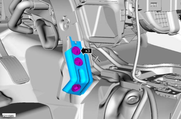
Remove the nuts and the LH insulator panel.
-
Disconnect the electrical connector.
Torque:
42 lb.in (4.8 Nm)
-
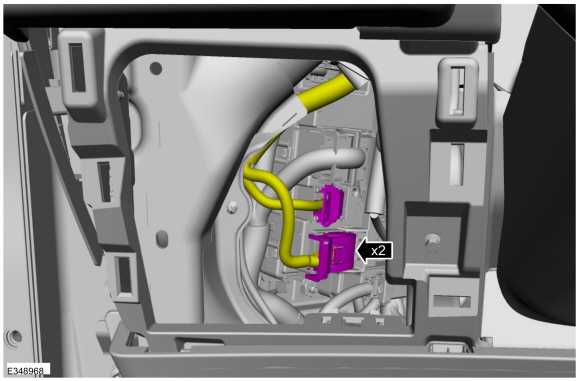
NOTE:
Acessed through opening on the LH side of the steering column.
Disconnect the BCM electrical connectors.
-
NOTICE:
Install a new steering column shaft bolt. Reuse
could result in bolt failure and loss of vehicle control. Failure to
follow this instruction may result in serious injury to vehicle
occupant(s).
Remove and discard the bolt and disconnect the steering column shaft.
Torque:
20 lb.ft (27.5 Nm)
-
Remove the bolts and the bracket.
Torque:
133 lb.in (15 Nm)
-
NOTE:
Leave the two instrument panel support bolts finger tight until the last step.
-
Remove the RH instrument panel support bolts.
Torque:
26 lb.ft (35 Nm)
-
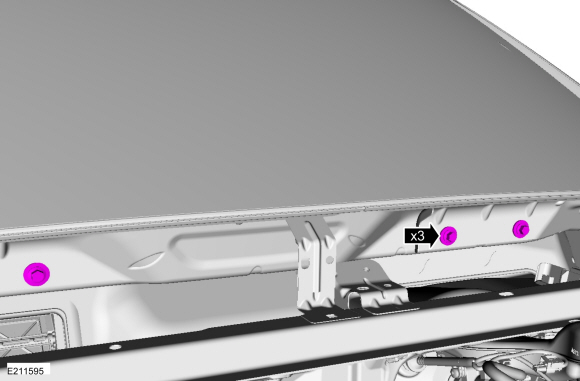
Remove the cover and the RH A-pillar to in-vehicle cross beam support bolt.
Use the General Equipment: Interior Trim Remover
Torque:
17 lb.ft (22.5 Nm)
-
NOTE:
Leave the two instrument panel support bolts finger tight until the last step.
-
Remove the LH instrument panel support bolts.
Torque:
26 lb.ft (35 Nm)
-
Remove the cover and the LH A-pillar to in-vehicle cross beam support bolt.
Use the General Equipment: Interior Trim Remover
Torque:
17 lb.ft (22.5 Nm)
-
NOTE:
To avoid damaging the instrument panel, an assistant is required when carrying out this step.
NOTE:
Make sure not to damage the instrument panel when removing the instrument panel from the vehicle.
NOTE:
Make sure that all electrical connectors and
wiring are not hindered before removing the instrument panel or damage
to the components may occur.
Rotate the instrument panel face down and remove through the RH front door opening.
Installation
-
To install, reverse the removal procedure.
-
Fill and bleed the cooling system.
Refer to: Engine Cooling System Draining, Vacuum Filling and Bleeding
(303-03B Engine Cooling - 2.7L EcoBoost (238kW/324PS), General
Procedures).
Refer to: Engine Cooling System Draining, Vacuum Filling and Bleeding
(303-03A Engine Cooling - 2.0L EcoBoost (184kW/250PS) – MI4, General
Procedures).
-
NOTE:
Anytime the parking brake switch electrical connector has been
disconnected, the EPB system is deactivated and a DTC is stored in the
ABS module. Perform the following step to restore the EPB system and
clear the ABS module DTC .
Apply and release the parking brake twice within 5
seconds, pausing with the switch in the NEUTRAL position for
approximately one-half second between each apply and release.
Removal
Fully lower the glove compartment.
Release the tabs.
Disconnect the dampener strap.
On both sides, rotate the hinge pin counter-clockwise through the opening...
Special Tool(s) /
General Equipment
Interior Trim Remover
Removal
WARNING:
Before beginning any service procedure in this
manual, refer to health and safety warnings in section 100-00 General
Information...
Other information:
Diagnostic Trouble Code (DTC) Chart
Diagnostics in this manual assume a certain skill level and knowledge of Ford-specific diagnostic practices. REFER to: Diagnostic Methods (100-00 General Information, Description and Operation).
NOTE:
Some Powertrain Control Module (PCM) Diagnostic Trouble
Codes (DTCs) may inhibit Air Conditioning (A/C) operation...
Removal
NOTE:
Removal steps in this procedure may contain installation details.
Both speakers
Remove the front door trim panel.
Refer to: Front Door Trim Panel (501-05 Interior Trim and Ornamentation, Removal and Installation).
Door woofer speaker
Remove the bolts and the front door speaker...
.jpg)
.jpg)
.jpg)
.jpg)
.jpg)

.jpg)
.jpg)
 Glove Compartment. Removal and Installation
 Instrument Panel Upper Section. Removal and Installation