Lincoln Nautilus: Glass, Frames and Mechanisms / Rear Door Window Regulator and Motor. Removal and Installation
Lincoln Nautilus 2018-2025 Service Manual / Body and Paint / Body and Paint / Glass, Frames and Mechanisms / Rear Door Window Regulator and Motor. Removal and Installation
Removal
NOTE: LH side shown, RH side similar.
NOTE: Removal steps in this procedure may contain installation details.
-
Remove the rear door trim panel.
Refer to: Rear Door Trim Panel (501-05 Interior Trim and Ornamentation, Removal and Installation).
-
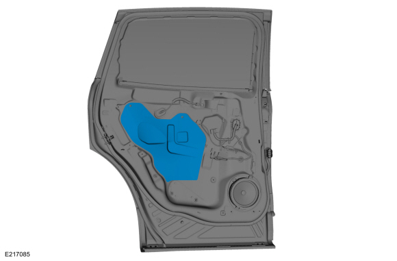
Remove the rear door watershield.
 |
-
Remove the rear door speaker.
-
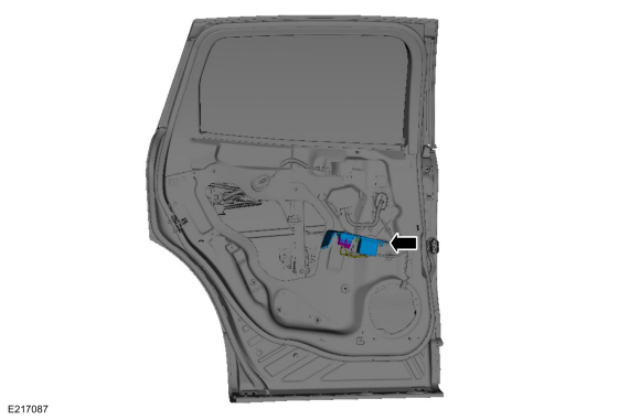
Disconnect the electrical connector and position aside the wiring harness.
-
Remove the retainers and remove the rear door speaker.
Torque: 22 lb.in (2.5 Nm)
-
Disconnect the electrical connector and position aside the wiring harness.
.jpg) |
-
NOTE: For non-functional rear door window regulators and motors with the window in the 40 mm open to full closed position, cut the rear door window regulator cables to allow window movement.
Lower the rear window glass to full down position.
-
Install the rear door window control switch.
-
Lower the rear window glass to full down position.
-
Install the rear door window control switch.
.jpg) |
-
Remove the rear door window control switch.
 |
-
Raise the rear door window glass to the full up position and tape in place.
-
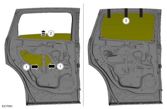
Remove the retainers from the rear door window glass.
-
Raise the rear door window glass to the full up position.
-
Tape the rear door window glass in place.
-
Remove the retainers from the rear door window glass.
 |
-
Remove the front door window regulator bolts and nut.
-
Disconnect the electrical connector and the position aside the wiring harness.
-
Remove the nuts and the bolt.
Torque: 93 lb.in (10.5 Nm)
-
Rotate the rear door window regulator and motor.
-
Remove the rear door window regulator and motor.
-
Disconnect the electrical connector and the position aside the wiring harness.
.jpg) |
-
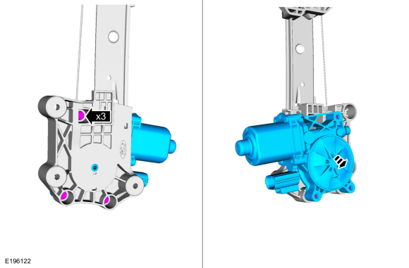
NOTE: This step is only necessary when installing a new component.
Remove the retainers and the rear door window regulator motor.
 |
Installation
- To install, reverse the removal procedure.
-
If the door is equipped with one touch up/down, carry out the power door window initialization.
Refer to: Power Door Window Initialization (501-11 Glass, Frames and Mechanisms, General Procedures).
 Rear Door Window Glass. Removal and Installation
Removal
NOTE:
LH side shown, RH side similar.
Remove the rear door trim panel.
Refer to: Rear Door Trim Panel (501-05 Interior Trim and Ornamentation, Removal and Installation)...

Other information:
Lincoln Nautilus 2018-2025 Service Manual: Rear Suspension Height Sensor. Removal and Installation
Removal NOTE: Removal steps in this procedure may contain installation details. Position vehicle on a hoist. Refer to: Jacking and Lifting - Overview (100-02 Jacking and Lifting, Description and Operation). NOTE: RH height sensor assembly shown, LH similar. If equipped. Disconnect the rear height sensor electrical connector. If equipped. Unclip and ..
Lincoln Nautilus 2018-2025 Service Manual: Front Door Moulding. Removal and Installation
Removal NOTE: LH side shown, RH side similar. NOTE: Removal steps in this procedure may contain installation details. NOTICE: To avoid damage to moulding, only use moderate force. Using a non-marring trim removal tool, disengage the retainer clips. Remove the moulding. Installation To install, reverse the re..
Categories
- Manuals Home
- 1st Generation Nautilus Owners Manual
- 1st Generation Nautilus Service Manual
- Normal Scheduled Maintenance
- Power Outlet - Vehicles With: 110V Power Outlet
- Switching the Lane Keeping System On and Off. Switching the Lane Keeping System Mode
- New on site
- Most important about car
USB Ports
Locating the USB Ports
Data Transfer USB Ports

The USB Ports could be in the following locations:
On the lower instrument panel. Inside the media bin. Inside the center console.Note: These USB ports can also charge devices.
Copyright © 2025 www.linautilus.com