Lincoln Nautilus: Rear End Sheet Metal Repairs / Rear Floor Panel Reinforcement. Removal and Installation
Special Tool(s) / General Equipment
| 8 mm Drill Bit | |
| MIG/MAG Welding Equipment | |
| Spot Weld Drill Bit | |
| Locking Pliers |
Materials
| Name | Specification |
|---|---|
| Seam Sealer TA-2-B, 3M™ 08308, LORD Fusor® 803DTM |
- |
Removal
NOTE: Factory welds may be substituted with resistance or metal inert gas (MIG) plug welds. Resistance welds may not be placed directly over original location. They must be placed adjacent to original location and match factory welds in quantity. Metal inert gas (MIG) plug welds must equal factory welds in both location and quantity.
NOTE: Adequately protect all adjacent areas against cutting, grinding and welding procedures.
-
Depower the SRS .
Refer to: Supplemental Restraint System (SRS) Depowering (501-20B Supplemental Restraint System, General Procedures).
-
Remove the rear Subframe.
Refer to: Rear Subframe - AWD (502-00 Uni-Body, Subframe and Mounting System, Removal and Installation).
Refer to: Rear Subframe - FWD (502-00 Uni-Body, Subframe and Mounting System, Removal and Installation).
-
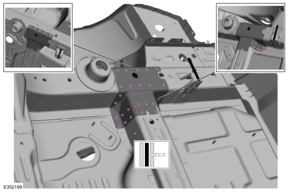
NOTE: Left hand (LH) side shown, right hand (RH) side similar.
On Both Sides:
Remove the welds.
Use the General Equipment: Spot Weld Drill Bit
 |
-
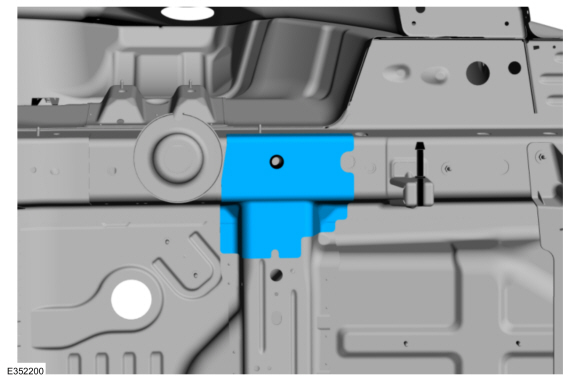
NOTE: Left hand (LH) side shown, right hand (RH) side similar.
On Both Sides:
Remove the panel.
 |
-
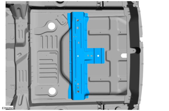
Remove the welds.
Use the General Equipment: Spot Weld Drill Bit
.jpg) |
-
Remove the Rear Floor Panel Reinforcement.
 |
Installation
NOTE: Factory welds may be substituted with resistance or metal inert gas (MIG) plug welds. Resistance welds may not be placed directly over original location. They must be placed adjacent to original location and match factory welds in quantity. Metal inert gas (MIG) plug welds must equal factory welds in both location and quantity.
NOTE: Adequately protect all adjacent areas against cutting, grinding and welding procedures.
-
Drill plug weld holes in the replacement reinforcement.
Use the General Equipment: 8 mm Drill Bit
.jpg) |
-
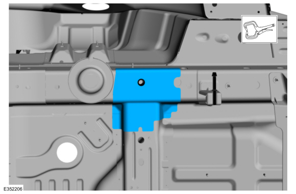
Install, properly position, clamp the replacement reinforcement.
Use the General Equipment: Locking Pliers
.jpg) |
-
Install the welds.
Use the General Equipment: MIG/MAG Welding Equipment
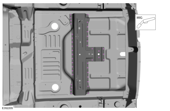 |
-
NOTE: Left hand (LH) side shown, right hand (RH) side similar.
On Both Sides:
Install, properly position, clamp the replacement panel.
Use the General Equipment: Locking Pliers
 |
-
NOTE: Left hand (LH) side shown, right hand (RH) side similar.
On Both Sides:
Install the welds.
Use the General Equipment: MIG/MAG Welding Equipment
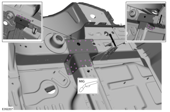 |
-
Dress all welds as required using typical metal finishing techniques.
-
Seam Sealing:
All seams must be sealed to production level.
Material: Seam Sealer / TA-2-B, 3M™ 08308, LORD Fusor® 803DTM
-
Refinish the entire repair using a Ford approved paint system.
-
Restore corrosion protection.
Refer to: Corrosion Prevention (501-25 Body Repairs - General Information, General Procedures).
-
Install the rear subframe.
Refer to: Rear Subframe - AWD (502-00 Uni-Body, Subframe and Mounting System, Removal and Installation).
Refer to: Rear Subframe - FWD (502-00 Uni-Body, Subframe and Mounting System, Removal and Installation).
-
Repowering the SRS .
Refer to: Supplemental Restraint System (SRS) Repowering (501-20B Supplemental Restraint System, General Procedures).
 Rear Floor Panel Crossmember. Removal and Installation
Special Tool(s) /
General Equipment
8 mm Drill Bit
MIG/MAG Welding Equipment
Spot Weld Drill Bit
Locking Pliers
Materials
Name
Specification
Seam SealerTA-2-B, 3M™ 08308, LORD Fusor® 803DTM
-
Removal
NOTE:
Factory welds may be substituted with resistance or metal
inert gas (MIG) plug welds...
 Rear Floor Panel Section. Removal and Installation
Special Tool(s) /
General Equipment
Spherical Cutter
Grinder
Air Body Saw
MIG/MAG Welding Equipment
Spot Weld Drill Bit
Materials
Name
Specification
Flange SealantCU7Z-19B508-A
WSS-M2G348-A11
Removal
Restore vehicle to pre-accident dimensions, if required...
Other information:
Lincoln Nautilus 2018-2026 Service Manual: Fuel Filler Door Assembly. Removal and Installation
Special Tool(s) / General Equipment Flat Headed Screw Driver Knife Removal NOTE: The fuel filler door assembly is damaged during the removal process and requires a new fuel filler door assembly installed. Remove the fuel filler door...
Lincoln Nautilus 2018-2026 Service Manual: Direct Current/Alternating Current (DC/AC) Inverter. Removal and Installation
Removal WARNING: Disconnect the 12 volt battery before servicing the direct current to alternating current (DC-AC) inverter or alternating current (AC) powerpoint to prevent the risk of high voltage shock. Failure to follow this instruction may result in serious personal injury...
Categories
- Manuals Home
- 1st Generation Nautilus Owners Manual
- 1st Generation Nautilus Service Manual
- Power Outlet - Vehicles With: 110V Power Outlet
- Child Safety Locks
- Opening and Closing the Hood
- New on site
- Most important about car
Clearing the Garage Door Opener. Reprogramming the Garage Door Opener. Garage Door Opener Radio Frequencies
Clearing the Garage Door Opener