Lincoln Nautilus: Seatbelt Systems / Rear Seatbelt Retractor and Pretensioner. Removal and Installation
Removal
 WARNING:
The following procedure prescribes critical repair steps
required for correct restraint system operation during a crash. Follow
all notes and steps carefully. Failure to follow step instructions may
result in incorrect operation of the restraint system and increases the
risk of serious personal injury or death in a crash.
WARNING:
The following procedure prescribes critical repair steps
required for correct restraint system operation during a crash. Follow
all notes and steps carefully. Failure to follow step instructions may
result in incorrect operation of the restraint system and increases the
risk of serious personal injury or death in a crash.
NOTE: Removal steps in this procedure may contain installation details.
NOTE: LH shown, RH similar.
-
Refer to: Pyrotechnic Device Health and Safety Precautions (100-00 General Information, Description and Operation).
WARNING:
Before beginning any service procedure in this
manual, refer to health and safety warnings in section 100-00 General
Information. Failure to follow this instruction may result in serious
personal injury.
-
Depower the SRS .
Refer to: Supplemental Restraint System (SRS) Depowering (501-20B) .
-
Remove the C-pillar trim panel.
Refer to: C-Pillar Trim Panel (501-05) .
-
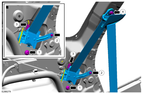
Remove the rear seatbelt retractor and pretensioner.
-
Remove the bolt.
Torque: 30 lb.ft (40 Nm)
-
Remove the bolt.
Torque: 106 lb.in (12 Nm)
-
Disconnect the electrical connector.
-
Remove the D-ring bolt and the rear seatbelt retractor and pretensioner.
Torque: 30 lb.ft (40 Nm)
-
Remove the bolt.
 |
Installation
WARNING:
Incorrect repair techniques or actions can cause an
accidental Supplemental Restraint System deployment. Make sure the
restraint system is depowered before reconnecting the component. Refer
to the Supplemental Restraint System depowering General Procedure in
section 501-20B. Failure to precisely follow depowering instructions
could result in serious personal injury from an accidental deployment.
NOTE: During installation, make sure the seatbelt webbing is not twisted and the seatbelts and buckles are accessible to the occupants.
-
To install, reverse the removal procedure.
-
Repower the SRS .
Refer to: Supplemental Restraint System (SRS) Repowering (501-20B) .
-
Check the seatbelt system for correct operation.
Refer to: Seatbelt Systems (501-20A Seatbelt Systems, Diagnosis and Testing).
 Seatbelt Shoulder Height Adjuster. Removal and Installation
Removal
NOTE:
Removal steps in this procedure may contain installation details.
NOTE:
LH shown, RH similar.
Remove the B-pillar trim panel...

Other information:
Lincoln Nautilus 2018-2026 Service Manual: Specifications
Materials Name Specification XY-75W-QL - Motorcraft® Disconnect Rear Drive Unit Fluid - Premium Long-Life Grease XG-1-E1 ESA-M1C75-B Capacities Item Liters Material: Motorcraft® Disconnect Rear Drive Unit Fluid / XY-75W-QL 0.860L (1.8 pts) (..
Lincoln Nautilus 2018-2026 Service Manual: Wireless Accessory Charging Module (WACM). Removal and Installation
Removal NOTE: Removal steps in this procedure may contain installation details. NOTE: If installing a new module, it is necessary to upload the module configuration information to the scan tool prior to removing the module. This information must be downloaded into the new module after installation. If installing a new module, it is necessary to upload the module configuration inf..
Categories
- Manuals Home
- 1st Generation Nautilus Owners Manual
- 1st Generation Nautilus Service Manual
- Opening the Liftgate
- Locating the Pre-Collision Assist Sensors
- Anti-Theft Alarm System Settings. Security – Troubleshooting
- New on site
- Most important about car
USB Ports
Locating the USB Ports
Data Transfer USB Ports

The USB Ports could be in the following locations:
On the lower instrument panel. Inside the media bin. Inside the center console.Note: These USB ports can also charge devices.