Lincoln Nautilus: Suspension System - General Information / Ride Height Measurement. General Procedures
Lincoln Nautilus 2018-2026 Service Manual / Chassis / Suspension / Suspension System - General Information / Ride Height Measurement. General Procedures
Special Tool(s) / General Equipment
| Surface Gauge |
Check
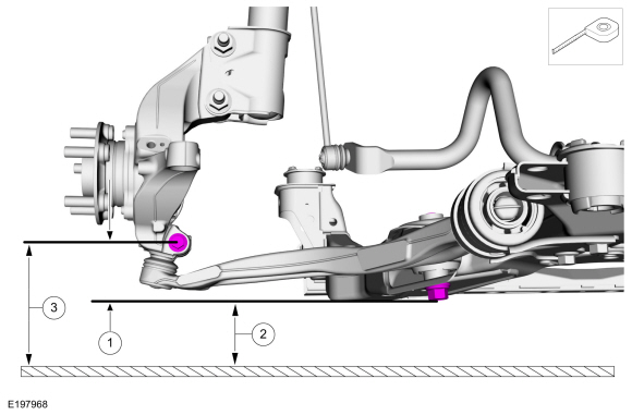
Ride Height Measurement - Front
NOTE: Make sure that the vehicle is positioned on a flat, level surface and the tires are inflated to the correct pressure. Vehicle should have a full tank of fuel.
-
-
Ride height = 3-2
-
Measure the distance between the flat level
surface and the center of the lower arm forward bolt (measurement 2)
-
Measure the distance between the flat level
surface and the center of the ball joint pinch bolt (measurement 3)
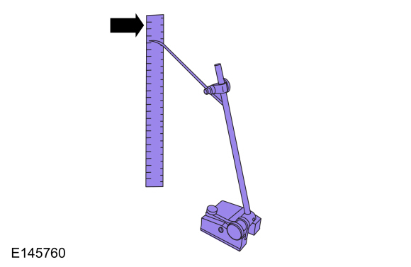
Use the General Equipment: Surface Gauge
-
Ride height = 3-2
 |
-
With the surface gauge positioned on a flat, level
surface, record the measurement of the surface gauge position
(measurement 2) and (measurement 3).
Use the General Equipment: Surface Gauge
 |
-
Subtract measurement 2 from measurement 3 to obtain the front ride height.
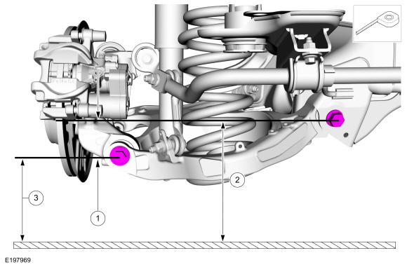
Ride Height Measurement - Rear
NOTE: Make sure that the vehicle is positioned on a flat, level surface and the tires are inflated to the correct pressure. Vehicle should have a full tank of fuel.
-
-
Ride height = 3-2
-
Measurement 2
-
Measurement 3
Use the General Equipment: Surface Gauge
-
Ride height = 3-2
 |
-
Measure the distance between the flat level surface
and the center of the rearward lower arm-to-frame bolt (measurement 2).
-
Measure the distance between the flat level surface
and the center of the lower arm-to-knuckle bolt (measurement 3).
-
Subtract measurement 2 from measurement 3 to obtain the rear ride height.
 Rear Toe Adjustment. General Procedures
Special Tool(s) /
General Equipment
Wheel Alignment System
Adjustment
NOTICE:
Do not use any tools or equipment to move the wheel and tire
assembly or suspension components while checking for relative movement...

Other information:
Lincoln Nautilus 2018-2026 Service Manual: Front Turn Signal Lamp Bulb. Removal and Installation
Removal Remove the front turn signal lamp bulb. Disconnect the electrical connector. Remove the bulb holder. Remove the front turn signal lamp bulb. Installation To install, reverse the removal procedure. ..
Lincoln Nautilus 2018-2026 Service Manual: Perimeter Anti-Theft Alarm. Diagnosis and Testing
DTC Charts Diagnostics in this manual assume a certain skill level and knowledge of Ford-specific diagnostic practices. REFER to: Diagnostic Methods (100-00 General Information, Description and Operation). BCM DTC Chart DTC Description Action B109F:01 Intrusion Sensor Module: General Electrical Failure ..
Categories
- Manuals Home
- 1st Generation Nautilus Owners Manual
- 1st Generation Nautilus Service Manual
- Child Safety Locks
- Opening and Closing the Hood
- Auto-Start-Stop
- New on site
- Most important about car
Clearing the Garage Door Opener. Reprogramming the Garage Door Opener. Garage Door Opener Radio Frequencies
Clearing the Garage Door Opener
Copyright © 2026 www.linautilus.com