Lincoln Nautilus: Steering Column / Steering Column Tilt Motor. Removal and Installation
Lincoln Nautilus 2018-2026 Service Manual / Chassis / Steering System / Steering Column / Steering Column Tilt Motor. Removal and Installation
Removal
NOTE: Removal steps in this procedure may contain installation details.
-
Remove the steering column shrouds.
Refer to: Steering Column Shrouds (501-05 Interior Trim and Ornamentation, Removal and Installation).
-
Detach the tilt motor electrical connector.
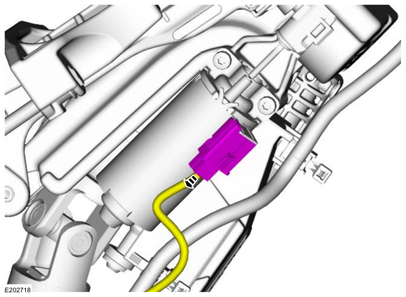 |
-
Remove the screws and the tilt motor.
Torque: 62 lb.in (7 Nm)
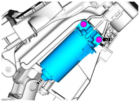 |
Installation
-
To install, reverse the removal procedure.
-
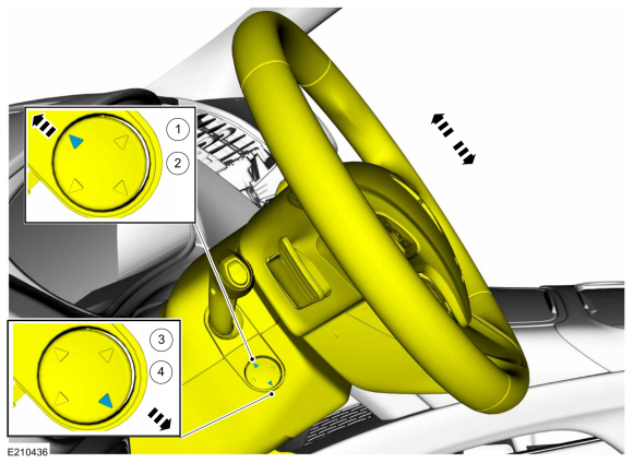
If equipped with memory steering column, use the
steering column control switch and set the tilt motor soft stops as
follows.
-
Move the column upward until it reaches the end of travel.
-
Move the column in the same direction until it reaches the end of travel again.
-
Move the column downward until it reaches the end of travel.
-
Move the column in the same direction until it reaches the end of travel again.
-
Move the column upward until it reaches the end of travel.
 |
-
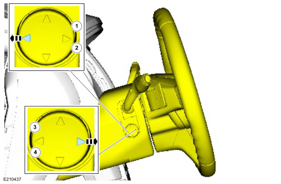
If equipped with memory steering column, use the
steering column control switch and set the telescopic motor soft stops
as follows.
-
Move the column rearward until it reaches the end of travel.
-
Move the column in the same direction until it reaches the end of travel again.
-
Move the column forward until it reaches the end of travel.
-
Move the column in the same direction until it reaches the end of travel again.
-
Move the column rearward until it reaches the end of travel.
 |
 Steering Column. Removal and Installation
Removal
NOTICE:
To prevent damage to the clockspring, make sure the front wheels are in the straight-ahead position.
NOTICE:
Precise tolerances are required when manufacturing a
steering column...
 Steering Wheel. Removal and Installation
Removal
NOTE:
Removal steps in this procedure may contain installation details.
NOTE:
Vehicle without heated steering wheel shown, others similar...
Other information:
Lincoln Nautilus 2018-2026 Service Manual: Passenger Knee Airbag. Removal and Installation
Removal WARNING: The following procedure prescribes critical repair steps required for correct restraint system operation during a crash. Follow all notes and steps carefully. Failure to follow step instructions may result in incorrect operation of the restraint system and increases the risk of serious personal injury or death in a crash...
Lincoln Nautilus 2018-2026 Service Manual: Vehicle Specific Body Construction. Description and Operation
For recommended metal repair guidelines and recommendations, refer to the following illustrations and: For additional information, refer to: Specifications (501-25 Body Repairs - General Information, Specifications). Steel Type Legend Item Steel Type Color 1 Mild Steel Yellow 2 Bake Hardened Steel (BH) ..
Categories
- Manuals Home
- 1st Generation Nautilus Owners Manual
- 1st Generation Nautilus Service Manual
- Power Outlet - Vehicles With: 110V Power Outlet
- Massage Seats
- Locating the Pre-Collision Assist Sensors
- New on site
- Most important about car
Locating the Pre-Collision Assist Sensors

If a message regarding a blocked sensor or camera appears in the information display, something is obstructing the radar signals or camera images. The radar sensor is behind the fascia cover in the center of the lower grille. With a blocked sensor or camera, the system may not function, or performance may reduce. See Pre-Collision Assist – Information Messages.
Copyright © 2026 www.linautilus.com