Lincoln Nautilus: Steering Column / Steering Wheel - Vehicles With: Adaptive Steering. Removal and Installation
Lincoln Nautilus 2018-2026 Service Manual / Chassis / Steering System / Steering Column / Steering Wheel - Vehicles With: Adaptive Steering. Removal and Installation
Removal
NOTE: Removal steps in this procedure may contain installation details.
NOTE: Make sure the road wheels are in the straight ahead position, regardless of steering wheel position.
-
NOTE: This step is only necessary when installing a new component.
NOTE: The PMI process must begin with the current SECM installed. If the current SECM does not respond to the diagnostic scan tool, the tool may prompt for As-Built Data as part of the repair.
Using a diagnostic scan tool, begin the PMI process for the SECM following the on-screen instructions.
-
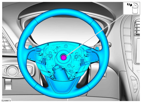
Remove the driver airbag.
Refer to: Driver Airbag - Vehicles With: Adaptive Steering (501-20B Supplemental Restraint System, Removal and Installation).
-
Remove the steering column shrouds.
Refer to: Steering Column Shrouds (501-05 Interior Trim and Ornamentation, Removal and Installation).
-
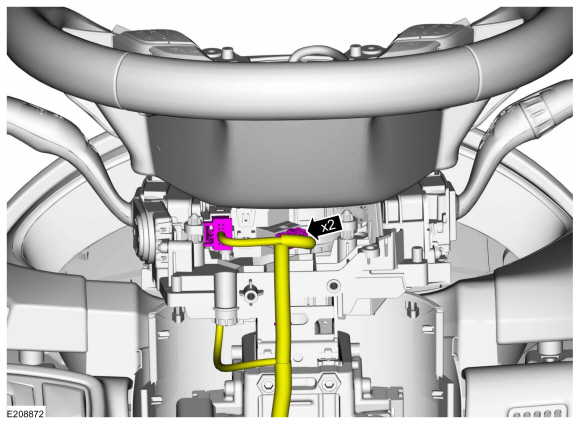
Disconnect the clockspring electrical connectors.
 |
-
Remove and discard the bolt and remove the steering wheel.
Torque: 35 lb.ft (47.5 Nm)
 |
Installation
-
To install, reverse the removal procedure.
-
NOTE: This step only necessary when installing new component.
Using a diagnostic scan tool, complete the PMI process for the SECM following the on-screen instructions and INSTALL as-built data from PTS for the SASM , following the diagnostic scan tool instructions under Module Programming>As-Built.
-
NOTE: This step only necessary when installing new component.
Using a diagnostic scan tool, complete the following service routines in the order shown, following the on-screen instructions.
-
Steering Wheel Angle Trim.
-
Steering Motor Angle Trim.
-
Steering Wheel Angle Trim.
-
Check and if necessary adjust front toe.
Refer to: Front Toe Adjustment - Vehicles With: Adaptive Steering (204-00 Suspension System - General Information, General Procedures).
 Steering Wheel. Removal and Installation
Removal
NOTE:
Removal steps in this procedure may contain installation details.
NOTE:
Vehicle without heated steering wheel shown, others similar...

Other information:
Lincoln Nautilus 2018-2026 Service Manual: Lower Arm Vertical Link. Removal and Installation
Special Tool(s) / General Equipment Vehicle/Axle Stands Removal NOTICE: Suspension fasteners are critical parts that affect the performance of vital components and systems. Failure of these fasteners may result in major service expense. Use the same or equivalent parts if replacement is necessary. Do not use a replacement part of lesser quality or substitute design. Tighten fast..
Lincoln Nautilus 2018-2026 Service Manual: Rear Driveshaft - 2.7L EcoBoost (238kW/324PS). Removal and Installation
Special Tool(s) / General Equipment Flat Headed Screw Driver Removal NOTE: Removal steps in this procedure may contain installation details. Remove the muffler and tailpipe. Refer to: Muffler and Tailpipe (309-00B Exhaust System - 2.7L EcoBoost (238kW/324PS), Removal and Installation). Remove the exhaust flexible pipe. Refer to: Exhaust Flexible Pipe (30..
Categories
- Manuals Home
- 1st Generation Nautilus Owners Manual
- 1st Generation Nautilus Service Manual
- Folding the Exterior Mirrors - Vehicles With: Manual Folding Mirrors. Folding the Exterior Mirrors - Vehicles With: Power Folding Mirrors
- Normal Scheduled Maintenance
- Engine Oil Capacity and Specification - 2.0L
- New on site
- Most important about car
Programming the Garage Door Opener to Your Garage Door Opener Motor
Copyright © 2026 www.linautilus.com