Lincoln Nautilus: Exterior Lighting / Trailer Module (TRM). Removal and Installation
Lincoln Nautilus 2018-2026 Service Manual / Electrical / Lighting / Exterior Lighting / Trailer Module (TRM). Removal and Installation
Removal
NOTE: This step is only necessary if the TRM is being replaced.
-
Using a diagnostic scan tool, begin the PMI process for the TRM following the on-screen instructions.
-
Remove the LH loadspace trim panel.
Refer to: Loadspace Trim Panel (501-05 Interior Trim and Ornamentation) .
-
Disconnect the electrical connectors, remove the screws and the TRM .
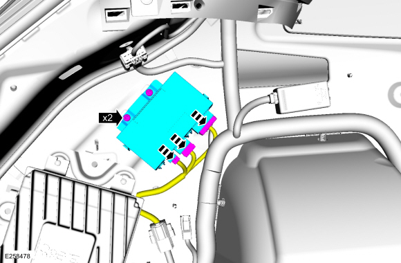 |
-
NOTE: This step is only necessary if the TRM is being replaced.
-
Depress the bracket tab.
-
Slide the bracket off the module.
-
Depress the bracket tab.
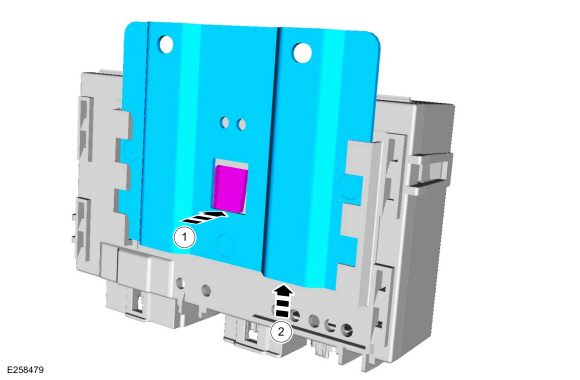 |
Installation
-
To install, reverse the removal procedure.
-
NOTE: Carry out this step only if a TRM is being replaced.
Using a diagnostic scan tool, complete the PMI process for the TRM following the on-screen instructions.
 Stoplamp Switch. Removal and Installation
Removal
NOTICE:
Do not press, pull or otherwise move the brake pedal while
installing the stoplamp switch and cruise control deactivation switch.
Install these switches with the booster push rod attached to the brake
pedal and with the brake pedal in the at-rest position...

Other information:
Lincoln Nautilus 2018-2026 Owners Manual: Drive Mode Control
What Is Drive Mode Control Your vehicle has various drive modes that you can select for different driving conditions. Depending on the drive mode that you select, the system adjusts various vehicle settings. How Does Drive Mode Control Work Drive mode control adjusts your vehicle configuration for each mode you select. Changing the drive mode changes the functionality of the steering system..
Lincoln Nautilus 2018-2026 Owners Manual: Keyless Entry Keypad Personal Access Codes
Programming a Personal Entry Code Enter the factory-set five-digit code. Press 1·2 on the keypad within five seconds. Enter your personal five-digit code. You must do this within five seconds of completing step 2. Press 1·2 on the keypad to save personal code 1. The doors lock then unlock to confirm that programming was successful. To program additional personal entry codes, repe..
Categories
- Manuals Home
- 1st Generation Nautilus Owners Manual
- 1st Generation Nautilus Service Manual
- Engine Oil Capacity and Specification - 2.0L
- Auto Hold
- Interior Lamp Function. Adjusting the Instrument Panel Lighting Brightness. Ambient Lighting. Interior Lighting – Troubleshooting
- New on site
- Most important about car
Clearing the Garage Door Opener. Reprogramming the Garage Door Opener. Garage Door Opener Radio Frequencies
Clearing the Garage Door Opener
Copyright © 2026 www.linautilus.com